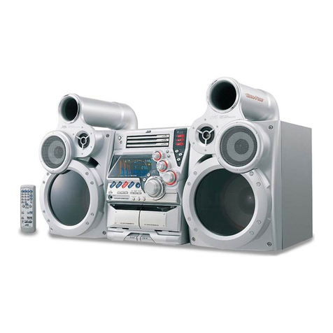
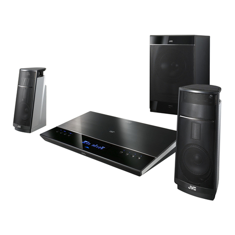
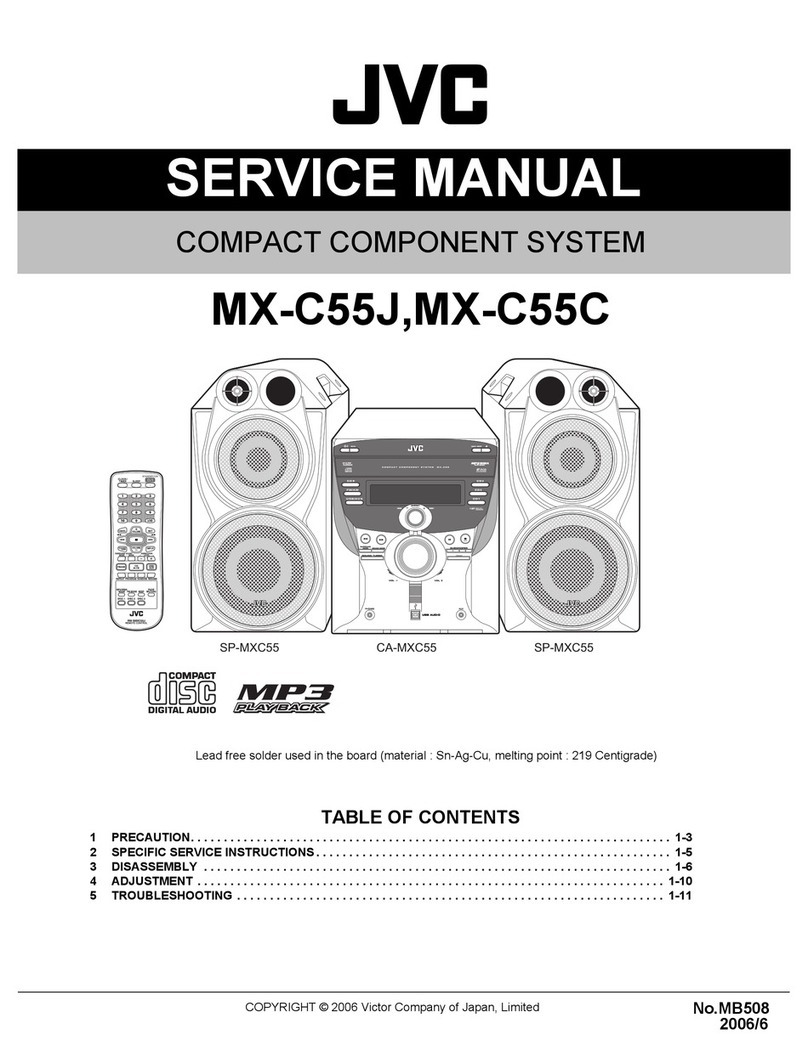
JVC NX-D4B User manual

SERVICE MANUAL
COPYRIGHT © 2010 Victor Company of Japan, Limited No.MB726<Rev.001>
2010/2
COMPACT COMPONENT SYSTEM
MB726<Rev.001>20102SERVICE MANUAL
NX-D4B,NX-D4E,NX-D4A
COPYRIGHT © 2010 Victor Company of Japan, Limited
Lead free solder used in the board (material : Sn-Ag-Cu, melting point : 219 Centigrade)
Lead free solder used in the board (material : Sn-Cu, melting point : 230 Centigrade)
TABLE OF CONTENTS
1 PRECAUTION. . . . . . . . . . . . . . . . . . . . . . . . . . . . . . . . . . . . . . . . . . . . . . . . . . . . . . . . . . . . . . . . . . . . . . . . . 1-4
2 SPECIFIC SERVICE INSTRUCTIONS . . . . . . . . . . . . . . . . . . . . . . . . . . . . . . . . . . . . . . . . . . . . . . . . . . . . . . 1-7
3 DISASSEMBLY . . . . . . . . . . . . . . . . . . . . . . . . . . . . . . . . . . . . . . . . . . . . . . . . . . . . . . . . . . . . . . . . . . . . . . . 1-7
4 ADJUSTMENT . . . . . . . . . . . . . . . . . . . . . . . . . . . . . . . . . . . . . . . . . . . . . . . . . . . . . . . . . . . . . . . . . . . . . . . 1-16
5 TROUBLESHOOTING . . . . . . . . . . . . . . . . . . . . . . . . . . . . . . . . . . . . . . . . . . . . . . . . . . . . . . . . . . . . . . . . . 1-17
except NX-D4A
SP-NXD3SP-NXD3 CA-NXD4

1-2 (No.MB726<Rev.001>)
SPECIFICATION
NX-D4 for Europe
Amplifier section
Output Power 230 W (115 W + 115 W) at 3 Ω(10% THD)
Audio Input AUDIO IN Stereo mini ( Ø 3.5 mm)
500 mV/47 kΩ(at “AUDIO LVL3”)
250 mV/47 kΩ(at “AUDIO LVL2”)
125 mV/47 kΩ(at “AUDIO LVL1”)
Digital Input/Output
OPTICAL DIGITAL OUTPUT (output only)
-21 dBm to -15 dBm (660 nm ± 30 nm)
USB REC/PLAY (input and output)
VIDEO OUT Color system PAL/NTSC (interlaced/progressive)
VIDEO (Composite) 1 V(p-p)/75 Ω
COMPONENT (Y) 1 V(p-p)/75 Ω
(PB/PR) 0.7 V(p-p)/75 Ω
Speaker impedance 3 Ω- 16 Ω
Tuner section
FM tuning range 87.50 MHz - 108.00 MHz
AM (MW) tuning range 522 kHz - 1 629 kHz
Disc player section
Dynamic range 80 dB
Horizontal resolution 500 lines
Wow and flutter Immeasurable
iPod section
Power supply DC 5 V 500 mA (each iPod dock)
USB section
USB specification Compatible with USB 2.0 Full Speed
Compatible device Mass storage class
Compatible system FAT16, FAT32
Output power DC 5 V 500 mA
General
Power requirements AC 230 V , 50 Hz
Power consumption 90 W (at operation)
1.00 W or less (at standby)
Dimensions (approx.) 195 mm ×333 mm ×313 mm (W ×H ×D)
Mass (approx.) 3.6 kg
System Speaker-SP-NXD3
Type 3-way 3-speaker Bass Reflex Type (Magnetically-Shielded Type)
Speaker units Tweeter 2.0 cm cone ×1
Mid Range 5.0 cm cone ×1
Woofer 16.0 cm cone ×1
Impedance 3 Ω
Power handling capacity 115 W
Frequency range 40 Hz - 20 000 Hz
Sound pressure level 84 dB/W·m
Dimensions 205 mm ×409.5 mm ×290.5 mm (W ×H ×D)
Mass 3.6 kg each

(No.MB726<Rev.001>)1-3
NX-D4 for A
Amplifier section
Output Power 230 W (115 W + 115 W) at 3 Ω(10% THD)
Audio Input AUDIO IN Stereo mini ( Ø 3.5 mm)
500 mV/47 kΩ(at “AUDIO LVL3”)
250 mV/47 kΩ(at “AUDIO LVL2”)
125 mV/47 kΩ(at “AUDIO LVL1”)
Digital Input/Output
OPTICAL DIGITAL OUTPUT (output only)
-21 dBm to -15 dBm (660 nm ± 30 nm)
USB REC/PLAY (input and output)
VIDEO OUT Color system PAL/NTSC (interlaced/progressive)
VIDEO (Composite) 1 V(p-p)/75 Ω
COMPONENT (Y) 1 V(p-p)/75 Ω
(PB/PR) 0.7 V(p-p)/75 Ω
Speaker impedance 3 Ω- 16 Ω
Tuner section
FM tuning range 87.50 MHz - 108.00 MHz
AM (MW) tuning range 522 kHz - 1 629 kHz
Disc player section
Dynamic range 80 dB
Horizontal resolution 500 lines
Wow and flutter Immeasurable
iPod section
Power supply DC 5 V 500 mA (each iPod dock)
USB section
USB specification Compatible with USB 2.0 Full Speed
Compatible device Mass storage class
Compatible system FAT16, FAT32
Output power DC 5 V 500 mA
General
Power requirements AC 240 V , 50 Hz
Power consumption 90 W (at operation)
16 W or less (at standby)
1 W or less (at ECO mode)
Dimensions (approx.) 195 mm ×333 mm ×313 mm (W ×H ×D)
Mass (approx.) 3.6 kg
System Speaker-SP-NXD3
Type 3-way 3-speaker Bass Reflex Type (Magnetically-Shielded Type)
Speaker units Tweeter 2.0 cm cone ×1
Mid Range 5.0 cm cone ×1
Woofer 16.0 cm cone ×1
Impedance 3 Ω
Power handling capacity 115 W
Frequency range 40 Hz - 20 000 Hz
Sound pressure level 84 dB/W·m
Dimensions 205 mm ×409.5 mm ×290.5 mm (W ×H ×D)
Mass 3.6 kg each

1-4 (No.MB726<Rev.001>)
SECTION 1
PRECAUTION
1.1 Safety Precautions
(1) This design of this product contains special hardware and
many circuits and components specially for safety purpos-
es. For continued protection, no changes should be made
to the original design unless authorized in writing by the
manufacturer. Replacement parts must be identical to
those used in the original circuits. Services should be per-
formed by qualified personnel only.
(2) Alterations of the design or circuitry of the product should
not be made. Any design alterations of the product should
not be made. Any design alterations or additions will void
the manufacturers warranty and will further relieve the
manufacture of responsibility for personal injury or property
damage resulting therefrom.
(3) Many electrical and mechanical parts in the products have
special safety-related characteristics. These characteris-
tics are often not evident from visual inspection nor can the
protection afforded by them necessarily be obtained by us-
ing replacement components rated for higher voltage, watt-
age, etc. Replacement parts which have these special
safety characteristics are identified in the Parts List of Ser-
vice Manual. Electrical components having such features
are identified by shading on the schematics and by ( ) on
the Parts List in the Service Manual. The use of a substitute
replacement which does not have the same safety charac-
teristics as the recommended replacement parts shown in
the Parts List of Service Manual may create shock, fire, or
other hazards.
(4) The leads in the products are routed and dressed with ties,
clamps, tubings, barriers and the like to be separated from
live parts, high temperature parts, moving parts and/or
sharp edges for the prevention of electric shock and fire
hazard. When service is required, the original lead routing
and dress should be observed, and it should be confirmed
that they have been returned to normal, after reassem-
bling.
(5) Leakage shock hazard testing
After reassembling the product, always perform an isola-
tion check on the exposed metal parts of the product (an-
tenna terminals, knobs, metal cabinet, screw heads,
headphone jack, control shafts, etc.) to be sure the product
is safe to operate without danger of electrical shock.Do not
use a line isolation transformer during this check.
• Plug the AC line cord directly into the AC outlet. Using a
"Leakage Current Tester", measure the leakage current
from each exposed metal parts of the cabinet, particular-
ly any exposed metal part having a return path to the
chassis, to a known good earth ground. Any leakage cur-
rent must not exceed 0.5mA AC (r.m.s.).
• Alternate check method
Plug the AC line cord directly into the AC outlet. Use an
AC voltmeter having, 1,000Ωper volt or more sensitivity
in the following manner. Connect a 1,500Ω10W resistor
paralleled by a 0.15µF AC-type capacitor between an ex-
posed metal part and a known good earth ground.
Measure the AC voltage across the resistor with the AC
voltmeter.
Move the resistor connection to each exposed metal
part, particularly any exposed metal part having a return
path to the chassis, and measure the AC voltage across
the resistor. Now, reverse the plug in the AC outlet and
repeat each measurement. Voltage measured any must
not exceed 0.75 V AC (r.m.s.). This corresponds to 0.5
mA AC (r.m.s.).
1.2 Warning
(1) This equipment has been designed and manufactured to
meet international safety standards.
(2) It is the legal responsibility of the repairer to ensure that
these safety standards are maintained.
(3) Repairs must be made in accordance with the relevant
safety standards.
(4) It is essential that safety critical components are replaced
by approved parts.
(5) If mains voltage selector is provided, check setting for local
voltage.
1.3 Caution
Burrs formed during molding may be left over on some parts
of the chassis.
Therefore, pay attention to such burrs in the case of pre-
forming repair of this system.
1.4 Critical parts for safety
In regard with component parts appearing on the silk-screen
printed side (parts side) of the PWB diagrams, the parts that are
printed over with black such as the resistor ( ), diode ( )
and ICP ( ) or identified by the " " mark nearby are critical
for safety. When replacing them, be sure to use the parts of the
same type and rating as specified by the manufacturer.
(This regulation dose not Except the J and C version)
Good earth ground
Place this
probe on
each exposed
metal part.
AC VOLTMETER
(Having 1000
ohms/volts,
or more sensitivity)
1500 10W
0.15 F AC TYPE

(No.MB726<Rev.001>)1-5
1.5 Preventing static electricity
Electrostatic discharge (ESD), which occurs when static electricity stored in the body, fabric, etc. is discharged, can destroy the laser
diode in the traverse unit (optical pickup). Take care to prevent this when performing repairs.
1.5.1 Grounding to prevent damage by static electricity
Static electricity in the work area can destroy the optical pickup (laser diode) in devices such as laser products.
Be careful to use proper grounding in the area where repairs are being performed.
(1) Ground the workbench
Ground the workbench by laying conductive material (such as a conductive sheet) or an iron plate over it before placing the
traverse unit (optical pickup) on it.
(2) Ground yourself
Use an anti-static wrist strap to release any static electricity built up in your body.
(3) Handling the optical pickup
• In order to maintain quality during transport and before installation, both sides of the laser diode on the replacement optical
pickup are shorted. After replacement, return the shorted parts to their original condition.
(Refer to the text.)
• Do not use a tester to check the condition of the laser diode in the optical pickup. The tester's internal power source can easily
destroy the laser diode.
1.6 Handling the traverse unit (optical pickup)
(1) Do not subject the traverse unit (optical pickup) to strong shocks, as it is a sensitive, complex unit.
(2) Cut off the shorted part of the flexible cable using nippers, etc. after replacing the optical pickup. For specific details, refer to the
replacement procedure in the text. Remove the anti-static pin when replacing the traverse unit. Be careful not to take too long a
time when attaching it to the connector.
(3) Handle the flexible cable carefully as it may break when subjected to strong force.
(4) I t is not possible to adjust the semi-fixed resistor that adjusts the laser power. Do not turn it.
1.7 Attention when traverse unit is decomposed
*Please refer to "Disassembly method" in the text for the pickup unit.
• Apply solder to the short land sections before the card wire is disconnected from the connector on the servo board. (If the card wire
is disconnected without applying solder, the pickup may be destroyed by static electricity.)
• In the assembly, be sure to remove solder from the short land sections after connecting the card wire.
1M
Conductive material
(conductive sheet) or iron palate
(caption)
Anti-static wrist strap
Solder short land section

1-6 (No.MB726<Rev.001>)
1.8 Important for laser products
1.CLASS 1 LASER PRODUCT
2.CAUTION :
(For U.S.A.) Visible and/or invisible class II laser radiation
when open. Do not stare into beam.
(Others) Visible and/or invisible class 1M laser radiation
when open. Do not view directly with optical instruments.
3.CAUTION : Visible and/or invisible laser radiation when
open and inter lock failed or defeated. Avoid direct
exposure to beam.
4.CAUTION : This laser product uses visible and/or invisible
laser radiation and is equipped with safety switches which
prevent emission of radiation when the drawer is open and
the safety interlocks have failed or are defeated. It is
dangerous to defeat the safety switches.
5.CAUTION : If safety switches malfunction, the laser is able
to function.
6.CAUTION : Use of controls, adjustments or performance of
procedures other than those specified here in may result in
hazardous radiation exposure.
REPRODUCTION AND POSITION OF LABELS and PRINT
!Please use enough caution not to
see the beam directly or touch it
in case of an adjustment or operation
check.
WARNING LABEL and PRINT

(No.MB726<Rev.001>)1-7
SECTION 2
SPECIFIC SERVICE INSTRUCTIONS
This service manual does not describe SPECIFIC SERVICE INSTRUCTIONS.
SECTION 3
DISASSEMBLY
3.1 Main body (Used figure were NX-D4E)
3.1.1 Removing the Top cover (See Fig.1, 2, 3, 4)
(1) Remove the six screws Aattaching the both Side panel.
(See Fig.1)
Fig.1
(2) Remove the six screws Battaching the both Side panel.
(See Fig.2)
Fig.2
(3) Disconnect the card wire from iPod board connected to
connector CN400 of the Main board. (See Fig.3)
(4) Disengage two hooks aengaged both side of the Top cov-
er. (See Fig.3)
Fig.3
(5) Disconnect the connector wire from Main board connected
to connector CN401 of the iPod switch board. (See Fig.4)
Fig.4
AA
B
hook a
CN400
CN401

1-8 (No.MB726<Rev.001>)
3.1.2 Removing the Rear panel (See Fig.5, 6)
(1) Disconnect the connector wire from FAN connected to con-
nector CN303 of the Main board. (See Fig.5)
(2) Disconnect the card wire from Tuner pack connected to
connector CN306 of the Main board. (See Fig.5)
Fig.5
(3) Remove the six screws Cattaching the Rear panel. (See
Fig.6)
Fig.6
3.1.3 Removing the Main board (See Fig.7)
(1) Disconnect the card wire from Front panel connected to
connectors CN301, CN312 of the Main board.
(2) Disconnect the parallel wire from Front panel connected to
connector CN315 of the Main board.
(3) Disconnect the card wire from Loader board connected to
connector CN307 of the Main board.
(4) Disconnect the connector wire from Power board connect-
ed to connector CN180 of the Main board.
(5) Disconnect the card wire from DVD mechanism connected
to connector CN309 of the Main board.
(6) Disconnect the card wire from USB board connected to
connector CN502 of the Main board.
(7) Disconnect the card wire from DVD board connected to
connector CN500 of the Main board.
(8) Disconnect the card wire from Amp board connected to
connector CN503 of the Main board.
(9) Disconnect the card wire from DVD board connected to
connector CN310 of the Main board.
(10) Disconnect the parallel wire from Amp board connected to
connector CN181 of the Main board.
(11) Disconnect the card wire from the Mic board connected to
connector CN304 of the Main board.
(12) Remove the two screws Dattaching the Main board.
Fig.7
CN303
CN306
CC
DD
CN301
CN312
CN309
CN502
CN500
CN503
CN310
CN181
CN304 CN315
CN307
CN180

(No.MB726<Rev.001>)1-9
3.1.4 Removing the DVD mechanism (See Fig.8)
(1) Disconnect the connector wire from USB board connected
to connector CN811 of the DVD board.
(2) Remove the two screws Eattaching the both side of the
DVD mechanism.
(3) Disengage two hooks bengaged both side of the DVD
mechanism.
Fig.8
3.1.5 Removing the Front panel (See Fig.9, 10)
(1) Remove the three screws Fattaching the Front panel. (See
Fig.9)
(2) Disengage one hook cengaged Front panel. (See Fig.9)
Fig.9
(3) Disengage two hooks dengaged both side of the Front
panel. (See Fig.10)
Fig.10
3.1.6 Removing the Amp board (See Fig.11)
(1) Disconnect the connector wire from power board connect-
ed to connector CN601 of the Amp board.
(2) Remove the two screws Gattaching the Amp board.
Fig.11
3.1.7 Removing the Power board (See Fig.12)
(1) Remove the four screws Hattaching the Power board.
Fig.12
3.1.8 Removing the iPod board (See Fig.13)
(1) Remove the six screws Jattaching the iPod board.
3.1.9 Removing the iPod switch board (See Fig.13)
(1) Remove the one screw Kattaching the iPod switch board.
Fig.13
Ehook b
CN811
hook c
F
hook d
CN601 G
H
H
JK

1-10 (No.MB726<Rev.001>)
3.1.10 Removing the FL board (See Fig.14)
(1) Remove the four screws Lattaching the FL board.
Fig.14
3.1.11 Removing the Touch sensor board (See Fig.15)
(1) Remove the four screws Mattaching the Volume board.
(2) Remove the two screws Nattaching the LED board.
CAUTION: The touch sensor board sticks to a Front
lens.
Fig.15
3.1.12 Removing the Mic board and USB board (See Fig.16)
(1) Remove the two screws Pattaching the Slide door.
(2) Remove the four screws Qattaching the Slide arm.
(3) Remove the four screws Rattaching the Shaft holder.
(4) Remove the seven screws Sattaching the Mic board and
USB board.
Fig.16
L
L
MN
P
Q
Q
R
R
P
Q
Q
R
R
S

(No.MB726<Rev.001>)1-11
3.2 DVD mechanism
3.2.1 Removing the traverse mechanism
(See Fig.1 to 6)
(1) Remove the two screws Aattaching the tramecha holder
from top side of DVD mechanism assembly. (See Fig.1)
(2) Remove the two screws Battaching the DVD module
board. (See Fig.2)
(3) Remove the four screws Cattaching the CB holder and
take out it. (See Fig.3)
(4) Remove the four screws Dattaching the traverse mecha-
nism. (See Fig.4)
(5) Solder the solder part of DVD pick up. (See Fig.5)
(6) Disconnect the card wire from CN101 and CN201 on the
DVD module board. (See Fig. 6)
Caution:
• Solder the short land section on the DVD pickup before dis-
connecting the card wire from the connector on the DVD
pickup. If the card wire is disconnected without attaching sol-
ders, the pickup may be destroyed by static electricity.
• When attaching the DVD pickup, be sure to remove solders
from the short land section after connecting the card wire to
the connector on the DVD pickup.
Fig.1
Fig.2
A
A
Clamper base
DVD mechanism assembly
B
B
DVD module board
DVD mechanism assembly

1-12 (No.MB726<Rev.001>)
Fig.3
Fig.4
Fig.5
Fig.6
CC
C
C
DVD module board
DD
Traverse mechanism assembly
DVD mechanism assembly
Solder short land section
CN101
CN201
DVD module board

(No.MB726<Rev.001>)1-13
3.2.2 Removing the pickup assembly
(See Fig.7 to 11)
(1) Remove the two rod springs pressing the guide shaft. (See
Fig.7)
(2) Remove the screw Eand Fattaching the spring holder.
(See Fig.8)
(3) Remove the read screw from traverse mechanism assem-
bly. (See Fig.9)
Caution:
When remove the lead screw, do not loss the middle
gear. (See Fig.10 and 11)
(4) Remove the bar spring pressing the shaft. (See Fig.10)
(5) Take out the pickup assembly from traverse mechanism
chassis by order. (See Fig.11)
Fig.7
Fig.8
Fig.9
Fig.10
Fig.11
ROD SPRING ROD SPRING
EF
Spring holder
Lead screw
Middle gear
(T.TABLE)
HOOK
(SHAFT)
(BAR SPRING)
order 1
order 2
order 3

1-14 (No.MB726<Rev.001>)
3.2.3 Removing the feed motor assembly
(See Fig.12)
(1) Remove the one screw Gattaching the feed motor assem-
bly.
(2) Remove the feed motor wires from solder part of spindle
motor board.
Fig.12
3.2.4 Removing the spindle motor assembly
(See Fig.13)
(1) Remove the three screws Hattaching the spindle motor
from spindle motor board.
Fig.13
Lead screw
Middle gear
Splder part
G
Spindle motor
H

(No.MB726<Rev.001>)1-15
3.2.5 Removing the tray assembly
(See Fig.14 & 15)
(1) Remove the two screws Jattaching the clamper base.
(See Fig.14)
(2) Remove the one screw Kattaching the shaft guide from
bottom side. (See Fig.14)
(3) Remove the two screws Lattaching the shaft guide from
top side. (See Fig.15)
Caution:
When attach the tray assembly, boss of loading sub assembly
should attach to guide of bottom side at tray assembly. (See
Fig.15)
Fig.14
Fig.15
J
order 1
order 2
clamper base
K
[bottom side]
L

1-16 (No.MB726<Rev.001>)
SECTION 4
ADJUSTMENT
4.1 ATTENTION IN SERVICE OF DVD SECTION
1. When pickup, Flash ROM, DVD module board was changed, initialize EEPROM by all means.
2. When full initialization was executed, execute learning with a DVD test disc by all means.
Test disc: VT-501, VT-502
Learning method: It is adjusted automatically by normal playback of a DVD disc.
4.2 GENERAL
*Note :
(1) Tray Lock while press and hold panel "STOP" key then press "EJECT"
(2) AM spacing (In power on AM source, panel keys)
4.3 SYSTEM MICOM TEST MODE
(1) In DVD/CD mode, press "SET" key + "10" key + "POWER" key repeatedly.
REMOTE KEY Validation INDICATION FUNCTION
STOP + "0" + POWER Press during Standby COLD COLD START (Initialization of set)
STOP + "1" + POWER Press during Power On (FL all light up) After CLOCK SET, run 1 minutes as 1sec
STOP + "2" + POWER Press during DVD/CD or USB eg:"A0D0S0T03BC" DVD temperature feedback
STOP + "3" + POWER Press once anytime eg: "POWERKEY" Power off/Safety trigger factor/cause
STOP + "4" + POWER Press during Power On eg:"FAN ON" Fan on/off trigger
STOP + "5" + POWER Press during Power On L0 C/SF/SH/SL/SE Lev_Det Status (L0/1/2), Calorie C****, Karaoke Score
SH,SF,SE,SL.
STOP + "6" + POWER Press during Power On VOLUME 15/MAX Trigger vol 15 or max
SET + "10" + POWER Press during Power On Refer SYSCON TEST Refer SYSCON TEST sheet
NX-D4
9K I<< + KARAOKE SCORING
10K >>I + KARAOKE SCORING
System micom version
NX-D4 : "S D4 E 5600"
DVD/CD firmware version
"DVD 0317"
USB Telechip version
"USB 0000"
Touch Sensor
"TS 08"

(No.MB726<Rev.001>)1-17
4.4 Version reduction
4.4.1 Version setting writing way
Version information is written in test mode.
And version writing can do only first time.
After change version, password must be input if version need change.
(1) Step
1.Set goes DVD test mode.
2.Press remocon B336 (STOP+6+POWER) key
3.If first time, set show " VERSION U1"(Initial value)
If already updated, set show "LOCKED"
4.If number key is pressed , system show version.
(Refer to Version chart)
5.For NX-D4, if SETUP key is pressed, system show "OK"
"and write version to FLASH ROM.
(2) Step for LOCK release
3.If already updated, set show "LOCKED"
4.Enter password by number key.(4digit:0115)
*Note : Same password for all NX-D Series
5.If SETUP key is pressed and number is correct,
system show "OK" and write to flash.
If number is wrong, system show "NG".
Version
Notes
-Version can be changed for U versions, E and JC.
-Initial setting is U1.
-Version setting must backup and don't clear after cold set.
SECTION 5
TROUBLESHOOTING
This service manual does not describe TROUBLESHOOTING.
TEST xxy v w
U1
LOCKED
U2
U2 O K
LOCKED
*___
****
***_
*
1st
4th
3rd
2nd *__
**** O K
**** N G
Key123456
VersionU1U2U3U4JC E

(No.MB726<Rev.001>)
VSE
Printed in Japan
Victor Company of Japan, Limited
Home Entertainment Business Division Personal AV Operation 10-1,1chome,Ohwatari-machi,Maebashi-city,371-8543,Japan

SCHEMATIC DIAGRAMS
COMPACT COMPONENT SYSTEM
NX-D4BNX-D4ENX-D4A
(No.MB726<Rev.001>)1/
36

■PRECAUTIONS ON SCHEMATIC DIAGRAMS
zDue to the improvement in performance, some part numbers shown in the circuit diagrams
may not agree with those indicated in the Parts List.
zThe parts numbers, values and rated voltage etc. in the Schematic Diagrams are for
reference only.
zSince the circuit diagrams are standard ones, the circuits and circuit constants may be
subject to change for improvement without any notice.
■PRECAUTIONS ON PARTS LIST
zThe parts identified by the symbol are critical for safety. Whenever replacing these parts, be sure to
use specified ones to secure the safety.
zThe parts not indicated in this Parts List and those which are filled with lines --- in the Parts No.
columns will not be supplied.
zP.W. BOARD Ass'y will not be supplied, but those which are filled with the Parts No. in the Parts No.
columns will be supplied.
zWhen ordering chips, screws etc., place bulk orders (unit of tens) whenever possible to improve
shipping efficiency.
zThere are cases where the actual implemented parts in the sets and the service parts are different.
When ordering parts, make sure to refer to the Parts List.
■PRECAUTIONS ON SERVICE
Certain parts of the power circuits and the GNDs differ according to the models. Care must be
taken for the following points as the differences are indicated separately in the LIVE GND ( ) and
the ISOLATED (NEUTRAL) GND ( ).
1. Do not touch the LIVE GND, or do not touch the LIVE GND and the ISOLATED (NEUTRAL)
GND at the same time. It may cause an electric shock.
Before pulling out the chassis or other parts, make sure to pull out the power cord from the
wall outlet first.
2. Do not short circuit between the LIVE GND and ISOLATED (NEUTRAL) GND, or never
measure the LIVE GND and ISOLATED (NEUTRAL) GND at the same time using measuring
instruments (oscilloscope, etc.). It may blow fuses or damage other parts.
■DEVIATION TOLERANCE RANGE
DEVIATION TOLERANCE RANGE
F G J K M N R H Z P
±1% ± 2% ±5% ±10% ±20% ±30% +30%
-10%
+50%
-10%
+80%
-20%
+100%
-0%
(No.MB726<Rev.001>)2/
36
This manual suits for next models
2
Table of contents
Other JVC Speakers System manuals

JVC
JVC EX-AK2DB Administrator Guide

JVC
JVC CA-MXJD8UW User manual

JVC
JVC SP-XF70 User manual

JVC
JVC CA-FS400 User manual

JVC
JVC UX-EP100 User manual

JVC
JVC MX-KB30 User manual

JVC
JVC CA-VSDT2000 User manual

JVC
JVC NX-PS1C User manual

JVC
JVC TH-WL315B User manual

JVC
JVC Compact Component System NX-PS2 User manual