JVC NIVIDO 3240GM User manual

NIVICO
No.
3109
SERVICE
MANUAL
MODEL
3240GM,
3240Sw,
3240SC
B/W
PORTABLE
TELEVISION
RECEIVER
DIMENSIONS
:
28.
5cm@,
7.2cm
HEIGHT
(Base),
18
7em[]
(Base)
WEIGHT:
5.2
kg
Se
TL
TMM
Ucn
mm
mt
Receiving
Channel
-
Antenna
VHF
:
toe
Consumption
;
“Fuse
-
Device
‘Speaker
:
Audio
|
Power
Output
:
Picture.
Tube.
ae
Transistors
:
|
Diodes
:
:
Cabinet
:
CCR
eR
VICTOR
SPE
Cle
TCA
TON
S
NEONATE
Channels
2
thru
12
VHF,
21
thru
69
UHF,
CCIR
sanders
Built
in
monopole
antenna
only
for
VHF,
75Q
unbalanced.
External
antenna
for
VHF
and
UHF,
300Q
balanced
Loop
antenna
for
UHF,
3002
balanced
AC
220Volts
50Hz
or
12Volts
D.C,
Le.
aoe
AC
220Volts
50Hz
21Watts,
12Volts
D.
C
11
Watts
200mA
slow
blow
type
and
1.
25A
slow
blow
type
3”
Round
type,
voice
coil
impedance
169,
.
500m
W
9
inch
90°
deflection
aluminized
26pcs
17pces
Plastics
COMPANY
OF
JAPAN,
LIMITED.
EC

SERVICING
IN
THE
FIELD
CLEANING
THE
CABINET
Clean
the
external
appearance
of
cabinet
body
and
the
stand
when
necessary,
using
a
clean
soft
cloth
with
mild
soap.
Don’t
use
any
solution
which
contains
benzine
or
petroleum.
RASTER
CENTERING
The
centering
device
is
2
magnetic
rings
located
on
yoke
rear
cover.
By
alternately
rotating
those
2
magnetic
rings,
the
picture
can
be
properly
centered
on
the
screen.
DEFLECTION
YOKE
ADJUSTMENT
If
the
lines
of
the
raster
are
not
horizontal
or
corner
shadows
appear,
loosen
the
yoke
clamp
screw
and
rotate
deflection
yoke,
pushing
yoke
snug
up
against
bell
of
picture
tube.
VERTICAL
HEIGHT
AND
VERTICAL
LINEALITY
ADJUSTMENTS
When
the
upper
or
lower
part
of
picture
extends
or
shrinks,
adjust
the
Vertical
Height
and
Vertical
Lineality
controls
alternately
to
fill
the
screen
\
inch
beyond
the
mask
until
the
picture
on
test
pattern
is
symmetrical
from
top
to
Bottom.
The
Height
control
extends
(or
shrinks)
mainly
a
lower
part
of
raster,
and
the
lineality
control
a
upper
part.
B
VOLTAGE
(12V)
ADJUSTMENT
Be
sure
to
maintain
at
220V,
50Hz
power
supply.
Then
adjust
the
12V
control
(R510)
at
D.
C.
12
volts
on
B
line.
AGC
ADJUSTMENT
Adjust
the
AGC
control
when
picture
is
a
very
slight
bend
at
it’s
top,
or
excessive
snow.
AGC
may
be
adjusted
by
tuning
control
fully
counter—clockwise
then
clockwise
until
there
is
a
very
slight
Bend
then
turn
control
counter-clockwise
just
sufficiently
to
remove
the
bend.
DISASSEMBLY
INSTRUCTIONS
REAR
COVER
REMOVAL
1.
Remove
2
screws
on
rear
cover
(Fig.
1)
and
5
screws
fastening
the
edge
of
rear
cover
(Fig.
2).
2.
Pulling
a
rear
cover
a
little,
disconnect
two
transmitting
leads
connected
to
antenna
terminals
and
speaker
leads
in
rear
cover,
Fig;
2
3240GM,
3240SW,
32405C
_
=
2
ort

Meas
Snare
erent
eee
Cn
me
ae.
TUNER
REMOVAL
Remove
rear
cover.
refer
to
‘Rear
Cover
Removal’.
Remove
VHF
and
UHF
selector
Knobs
and
VHF
and
UHF
fine
tuning
knobs.
Remove
3
arrow
head
screws
indicated
in
Fig.
3.
UHF
TUNER
Fig.
3
FRONT
PANEL
REMOVAL
=
All
parts
eae
tuner
bracket
in
a
front
panel
(namely
a
body)
are
fastened
up
CRT
inoidies
or
utilizing
it.
and
SO,
it
can
removed
all
parts
from
body
-by
removing
a
tuner
bracket
and
CRT
holder.
1.
:
2.
3.
Remove
rear
cover.
refer
to
“Rear
Cover
Removal’.
Remove
tuner
bracket.
refer
to
“Tuner
Removal’.
|
Remove
4
screws
fastening
CRT
holder
(Fig.
5).
Take
out
the
all
parts
contained
CRT
with
both
hands
by
having
the
CRT
face
all
together
from
the
Printed
Circuit
Board
on
right
hand
and
the
heat
sink
board
on
left
hand.
Fig.
4
is
the
photo
removed
all
parts
from
front
panel.
SCREWS
Fastening
CRT
Holder
-CRT
Holder
Fig.
5
PRINTED
CIRCUIT
BOARD
AND
HEAT
ae
REMOVAL
’
Remove
rear
cover.
refer
to
“Rear
Cover
Removal’.
In
case
of
Printed
Circuit
Board
“A”
(Fig.
6).
Remove
an
arrow
head
screws
and
disconnect
spring
indicated
in
Fig.
6.
and
ae
off
Printed
Circuit
Board.
|
:
3240GM
ONLY
SPRING
PRINTED
CIRCUIT
BOARD
‘A’
Fig.
6
3240GM,
3240SW,
3240SC

In
case
of
Printed
Circuit
Board
“B”
(Fig.
7).
Remove
two
screws
and
disconnect
two
springs
indicated
in
Fig.
7.
and
pull
off
Printed
Circuit
Board.
PRINTED
CIRCUIT
.
\
BOARD
“8”
SPRING
3240GM
ONLY
SCREW
,
4+
SPRING
en"
Fig.
7
In
case
of
Heat
Sink
Board
(Fig.
8).
Remove
three
screws,
and
pull
off
Heat
Sink
Board.
refer
to
Fig.
8.
al
SCREW
HEAT
SINK
BOARD
CRT
REMOVAL
_
ae
|
a
|
;
Refer
to
“Front
Panel
Removal’.
3240GM,
3240SW,
3240SC
|
a
|
|
|

ALIGNMENT
INSTRUCTIONS
PRE-ALIGNMENT
Use
of
an
isolation
transformer
to
protect
the
test
equipments
is
recommended.
Keep
the
main
voltage
at
220
volts
and
allow
10-minutes
warm-up
period
for
the
receiver
and
the
test
equipments.
PIX
IF
ALIGNMENT
TEST
EQUIPMENTS
a.
Sweep
generator
b.
Marker
generator
c.
Oscilloscope
d.
2~4
Volts
Battery
(for
AGC)
PREPARATION
BEFOR
ALIGNMENT
Connect
the
synchronized
sweep
voltage
from
the
sweep
generator
to
the
horizontal
input
of
oscilloscope
for
horizontal
deflection.
|
7
Set
the
channel
selector
to
any
non-interfering
channel,
connect
a
BIAS
Sipsiy
(3
volts)
to
the
IF
AGC
line
TP-3,-
and
adjust
the
IF
transformer
in
chart
1
to
obtain
a
response
curve.
PIX
IF
ALIGNMENT
PROCEDURE
Sweep
Generator
Oscilloscope
Marker
Generator
;
Marker
_
Wave
Form
Coupling
to
Coupling
to
Frequency
Adjustment
Position
36.7
MHz
MAX.
|
Fig.
9A
ee
TP-4
=<
34.4
MHz
60
~
80%
TP-4
oS
TP-2
|
TP-2
cm
36.7
MHz
Center
Fig.
9A
38.9
MHz
60~80%
40.4
MHz
MIN.
TP-1
33.4
MHz
MIN.
on
VHF
tuner
|
.
MAX.
Through
2000pF
|
Through
1s5KQ
|
capacitor
resistor
;
~36.7MHz
7
-
chart
1
36.
7MHz
38.9MHz
REMARK
34.4MHz
60~80%
70~50%
33.4MHz
40.4MHz
|
Fig.
9A
|
Fig.
9B.
As
to
marker
positions
of
36.7MHz
on
each
wave
form,
please
refer
to
PIX
IF
alignment
procedure
table.
SOUND
IF
ALIGNMENT
TEST
EQUIPMENTS
a.
5.5MHz
Oscillator
b.
V.
T.
V.
M.
with
RF
probe
SOUND
IF
ALIGNMENT
PROCEDURE
be
I
ae
|
ae
eae
324OGM,
3240SW,
32405C
STEP
|
Oscillator
coupling
to
|
V.
T.
V.
M.
coupling
to
|
Adjustment
|
Vv.
T. V.
M.
reading
1
|
TP-4
|
TP-5
|
T103
|
AX.
a,
ee:
Se
a
eee
2
|
pp
4
|
TP5
|
_—-T201
(pink
core)
|
AX.
-
T201
(black
core)

MECHANICAL
PART’S
DIAGRAM
(Replacement
Service
Parts)
Front
Panel
QZ
R2147-001
‘Rod
Antenna
A10229
Protector
Glass
Stand
Ass'y
SDSC
3008RS~X
4
Tap
Screw
A44323-A
Jack
Ass‘y
(VHF)
J3
A44323-B
Jack
Ass'y
(UHF)
J4
Antenna
Terminal
Rear
Cover
SBSB4010Z
Tap
Screw
Q03064
001
(model
3240GM)
T
42918
(model
3240SC)
er
Cord
With
Plug
Ass'y
Fig.
13
3240GM,
3240SW,
3240SC
Front
Panel
&
Stand
Front
Panel
Model
Name
Part’s
No.
White
3240GM,
3240SW,
3240SC
|
A10227-AS
|
A20684-00A
Red-Orange
|
3240GM
A10227-CS_
|
A20684-00C
Gray
3240GM
A10227-00F
A20684-00F
Orange
3240GM,
3240SW,
3240SC
|
A10227-00E
|
A20684-00E
-SHSA3010R
Tap
Screw
A31445-A
UHF
Knob
Ass:
A31443-00C
CH
Knob
Ass‘y
Assy
Fig.
12
Antenna
Terminal
&
Rear
Cover
Ant.
Terminal
Part’s
No.
Rear
Cover
Color
Part’s
No.
Model
Name
White
3240GM,
3240SW,
3240SC
|
A31521-001
|
A10228
Red-Orange
|
3240GM
|
A31521-003
|
A10228-3
Gray
—-|
3240GM
A31521-005
|
A10228-006
Orange
3240GM,
3240SW,
3240SC
|
A31521-004
|
A10228~005

}
MECHANICAL
PART’S
DIAGRAM
|
(Replacement
Service
Parts)
Ear.
Jack
Ass’y
Slide
Switch
Assy
$601
Q03940
31
Q03746-2
:
Q04202-005
Ceramic
Capacitor
C604
A31521-001
Antenna
holder
Holder
A44446
Tap
Screw
x
2
Screw
<
2
$BSB3008
Z
SPSP2006N
Holder
A44445
| —
Q03002-33
;
Lug
Strip
Ass’y
Lug
Strip
Ass'y
Q03002-44
MTrans
Assy
A44499-O0D
ne
SBSB40i8Z
Tap.
Screw
-§5246
Spring
Holder
44490
‘Bracket
Adsgg2-
1S
A44448
Bracket
A31442-001
Heat
Sink
A44560
Holder
|
Horder
A44553
Cord
Clamp
A31448
A31410
Connector
Bracket
Q03924-
00001
-
EXT.
Battery
J2
S501
Jack
Ass'y
A44491
Bracket
A44490
Holder
<
Fig
17
—T—
3240GM,
3240SW,
3240SC

BLOCK
DIAGRAM
St
mg
ee
Re
ee
7
|
2984
AH
TAO
“40H
AIG
"404
ex
(a)
€29VS2
(P@y)
VIasose
x
"INO
"249A
‘9S0
“349A
S$.
lpeaszerx
dgiiasz"x
Sraccemnanae
ieee
aHOA
U017}9a/$9G
’
BDV
07
LHD
“INQ
OVplA
“dwiy
oapi,
----—--—----
~~
yvahkoy
ODV
EI
IGEVSZX
SI
‘Sly
eres
eee
ee
rt
"
O4v
‘40H
(@)BSHDSZ"X
“ANI
8Seud
Ww
dag
‘suds
‘SeBopoSee
xX
‘duy
99¥
(D'BGROSZ
X
‘duy
At
X!id
Pie
‘dwy
ai
1A
96QISZ°X
(€)
#SbDSZ
PX
_
LILOSZEX
|
"yno
O1pMy
| :
‘Di
SLIVSZ"X
Og!
:
“duy
olpny
jag
oney,
uk
OSNI
sdyeadg
|
(0)8spOS2"x
sofa
"INQ
o1pny
ca
!
IDIEIZIISZX
a
eae
ey
a
a
a
ct
a
a
a
ar
fee
as
ta
.
(B)
ZBGDS7
IX
‘duty
Jos
(D)8SFOSZEX
‘duty
“Bay
(9)
8SFOSZ2X
‘Pay
“4nd
(a)
zeeasZ"
xX
"Jay
4aMOd
sguasarg
|
Z
HOG
|
AQ’ZOV
‘avis
|
at
viautia
|
|
{
OAV
“40H
|
ven}
i
tata
:
:
;
:
“dag
"QUA
:
GIWS0'X
|
$
vin
BHN]
|
ot
|
dW
v
3Hn
|
999S7..9%%
J
|
sngo
MAA
e
“XW
HA
vzeas
'a
‘9S
6911
997"X
0
‘oso
JHN
V88Z9S2
1X
“duiy
(du
“dusty
sl
Xtc
V5t
18
289DS2°X
Xl
PUZ
9099S2'X
"INV
JHA
“NY
AHN
(DipSpDSZ?!
X
ee
ee
m
|
|
|
|
|
|
|
|
3240GM,
3240SW,
3240SC

ees
J
ms
ee
ee
i
SON
os
i
es
sani
entre
“hs
2
eee
eee
ERSTE

TELEVISION
SCHEMATIC
DIAGRAM
:
|
~
i
Soe
te
ee
ig,
ee
‘a
NOTES
COMP
:
COMPOSITION
RESISTOR
RESISTORS
AND
CAPACITORS
ARE
RATED
Meese
4.
ALL
DC
VOLTAGES
ARE
MEASURED
WITH
VIVM.
AND
O
M
:OXIDE
METAL
FILM
RESISTOR
+10%
UNLESS
OTHERWISE
INDICATED.
Beer
WITH
NO
SIGNAL
INPUT.
UNSPECIFIED
POLARITY
WWR
:
WIRE.
WOUND
RESISTOR
.
(J)
5%
(M)t
20%
(P)+100%
-
0
%
(Z>+B0%
-
20%
\S
POSITIVE
NTH
:NEGATIVE
THERMISTOR
2
ALIGNMENT
4
ALL
CAPACITANCE
VALUES
LESS
THAN
/ARE
n
FRONT
OR
SIDE
———;
REAR
IN
MF
AND
ABOVE
/
ARE
IN
pF
UNLESS
OTHER-
—-»
|
OUT
SIDE
—--—y
IN
SIDE
WISE
INDICATED.UNSPECIFIED
CAPACITORS
3.
ALL
RESISTANCE
VALUES
IN
OHMS
ARE
CERAMIC
CAPACITORS.
K:
1000
M:1,000.000
—
P
S
:POLYSTYROL
CAPACITOR
[25WVt5%
UNSPECIFIED-RESISTORS
ARE
CARBON
RESISTORS
MY
:MYLAR
CAPACITOR
5OWV1I0%
I4W+tl0%
UNLESS
.
OTHERWISE
INDICATED.
P
P
:POLYPROPYLEN.
CAPACITOR
Xi2
25CAS4(C)
_-
SIF
AMP@
LIMIT
C203
OTP-6
4
201
S55
MH
27
FINE.
ib
C00
ent
X4
2SC
115
cx
osc
or
3
2
(
}
=
ips,
R204
=
1K
api
6
oe
s
)
=
B
LFOUT
=
330%
5
4
"
SS
SS
Se
Dé
R205
a
‘
N60
1K
X5
2SC682(B)
X6
2SC
682
(B)
CUT!
x9
2SC
B56
(ST
PIX
Ik
AMP
OND
PIX
IF
AMP
SDT
Sento
©
IB?
X8
2SC454(B)
et,
eke
et
“SRD
PIX
IF
AMP
_VEDEO
AMP
{0.0
eine
|
|
3
30
\
me,
D
LIO6
|
oy
|
ake
|
Lone
cye
lise
26
Te,
IND
Be
4.7K
1QV;
ot
S
RIIQ
|
0
——.
Y3
ae
|
cog
gn
a
a
Rex
Cio
ae
:
ma
20
CHB
Clea
hs
!
.
=
gee
oe
tbe
if
ra
Se
a
ee
/
y
RISS
|
ee
ee
|
|
RIB
5G
O)-—(O)
--
—©)
--
O
Lo
=
|
ie
A58(C)
0.05Y,
VA
La
een
ren
68
LaV
Pw
:
oN
ae
m
=
ie
300
Ok
"78
Sex
55
RIS4
Sour
p
DA
!
Ci
:
a
-
i
Sek
“Ba
“ey
|
ZW,
5.34
ak
wy
Zar)
KS
OSV)
257
nee
/
RS
ve
AGC
:
R301
|
_——
ez
——_—_
——
—
eee
ere
cst
F380!
Xr
2SC.458(B)_
[>
——
—
—
Ssh
ane
X24
2SB33'1(B)
25
(C)
—
e302
|
SR
BEE
oe
ERROR
AMP
aan
Ss
SEY
SYNC
SEP
PHASE.
|
XB2SBITE®
.
RED
: : :
Pe
sync
sep
Ree
=
one
|*
C302
2.
(
Musee
"C34
av
“4
\erv
|
WAS
4700)
as),
|
et
Ay
__lew
C
4
|
ne
ay
2B
SRB
(16429)
soil
a
25wv
o>
@
i
R307
we
ma
|
|!
Tos
me
ne,
at
Gi
@)
ian
ae
cole
50M
_
12.1V
|
=
—
|
VHEIGHT
Sa
:
=
ae
scasec)
|
|
=
i
ea!
Soe
Ue
REG
AMP
|
|
oe
X22
2SC6BIACRED)
PN
si
~
et
rai
xe
Be
|
oa
lege
|
AN
wey)
Fai
FUSE
-O1
P.P
"
R4
\
5
—
—
Leaciownom
|
|
pfQR
AFC
Soe
Se
l
LIV
1402
ae
|
|
my
R404
a
|
|
Ba
b
!
CRT
‘A’
R502
=|
C508,
509,
515
TRANS
|
|
=e
|
|
wv
S
|
Stl
fs
ov
oe
a
;
790!
:
40
Neo
aay
G-
7
On
ic.20Ren0
3240GM
|
230ACB4
|
2200
2W
|.
USE
cp
eaubacwneys
1
|
OS
Res
(BR
T
:
ae
ee
fis
=
cbok
In
|
3240SW
|
230ACB4
|
2202
2wW
|
NO
USE
'
|
at
le
paca
|
|
2
On
"Wr
7
|
|
|
aaa
ea
508
|
csog0
FUSE
|
C402
Ras
(210).
33
O—
—
+4
10.1502)
3240SC
|
230ACB4
-|
2200
2W
NO
USE
2100
amoC
ae
“dodn
1K
waoil
@)
Soe
‘
o
!
ar
S00
|
_4
le
oe
Coup
Poe
(0.52)
+|
Cais
rn
eee
eee
ee
ee
ee
ee
Beene
al
AC
220V
|
IX
»
LAV
45v
[
HHoLD
|
|
MOOMP
mS
220K
-
:
SOHE
|
Kugel
:
leno
Ff
bd
ay
*y
oe
|
|
H
1
C4
R415
Ay
{2
R417
|
|
|
Ae
ae
a
Bev
‘-
|
Bs
|
Re
a
ee
<n
ON
ag
nen
ne
nae
Oe
J
AN1004-001S
Printed
in
Japan

Electronic
Part’s
List
(Replacement
Service
Parts)
Part’s
No.
Part’s
Name
|
Symbol
No.
|
Part’s
No.
|
Part’s
Name
Symbol
No.
Transistors
&
Diodes.
A44586
Sound
IF
Trans.
Ass’y
T103,
C131
|
A44587
Ratio
Trans.
Ass’y
T201,202,C204
2502884
Transistor
,
|
X1
A42131-A
|
Hor.
Drive
Trans.
Ass’y
T402
2SC606
Wo
X2
A31478-A
_
HV.
Trans.
Ass’y
7403,
D12
250605
uy
X3
A44624-001
Choke
Coil
L601
2SC1159
r,
X4
(3240GM
only)
2SC682(B)
un
X5,
6
Sockets
(Connectors)
25C717
i
:
X7
| |
2SC454(B)
.
|
Pane
|
Q03940
Ear.
Jack
Ass’y
ji
oscase
-
|
4
Q03924-001
|
Ext.
Battery
Jack
J2,
S503.
2SC458(C)
fe
X10,
13,
23
A44397-B
CRT
Socket
Ass’y
vi
25A351(B)
oe
XL
Variable
Resistors
25C454(C)
MH
X12
2SA673IC)
)_.
.
:
|
Xu
Q04832-010
V.
Resistor
(SW-VOL)
R222,
$501,502
ee
¥
|
ae
Q04828-003
M"
(CONT)
R157
OSAI5
,
X16
Q04836-003
on
(BRIGHT)
R158
2SC458(B)
i
X17,
20
Q04843-3
"
(AGC.
HEIGHT)
|
R144,
325
~
25B176®
a
|
X18
Ww
2
7
(2v
ADJ.)
R510
2SB341V®@
a”
X19
Q04871-1
NW
CV.
LIN.)
R319.
2SA673(B)
no
|
X21
Q04832-011
it
CV.
HOLD)
R316
|
2SC681A(RED))
Ys
X22
Resistors
(Power
&
Special)
2SB337(B)
"
|
X24
|
2SC458(C)
ay
X23,
25
Q04784-—22
Wire
Wound
Resistor
R503
SD82A
Diode
D1
Q04772-220
Oxide
Metal
Resistor
R502
LN60-
,
D2
|
A03008-5
—
CR
Block
|
os
en
|
me
i,
QRW121J-R24
|
Wire
Wound
Resistor
R414
LN60(Pair)
.
Be.
.
A04292-4
Negative
Thermistor
R215
A04292-005
"
3
R322
A04093-X
it
D7
006
7
R320
A04230-A
"
D10
|
|
A04241-A
u
Dil
Electrolytic
Capacitors
A04332-007
Nn
D13
A04331-021
ii
D14,
15, 16,
17
Q03107-200
Elect
Capacitor
C602
|
Q03105-30
"
C603
C
RT
Ww
6-10
7]
|
C146
eS
|
Q03582-11
7
C501
230ACB4
CRT
és.
|
WE
Q03104-30
7
a
C144,
213
.
|
n
100
"
C127,
135
Coils
&
Transformers
-
Q03106-10
wo
C209
:
1
~=6
—200
7
:
C217
A31477-BZS
Def,
Yoke
Ass’y
a
Q03122-220°>
|”
cia’
cuales
aan
C308,
309
A44579
Trap
Coil
Ass’y
L102,
C103
Q03108-10
"
;
C214
A44580
©
"
|
L103,
C105
nw
~=-30
it
|
C132,
141,215
|
A04317-B
Hor.
Osc.
Coil
Ass’y
_
T401
#100
woo
C303,
408
A44383-B
Vert.
Out.
Coil
Ass’y
L301
—n-~
~200
7
|
C218,
414
442079
Choke
Coil
L401
“n
-500
i"
C314
A04096-22
Peaking
Coil
|
L106
n
=
~1000
i
|
C506
n
—-220
wo
L109
Q03110-3
on
C143,
216,
304
A44499-00D
M.
Trans.
Ass’y
T601
no
-5
Mo
|
©1142,
403
A44517
:
Power
Trans.
Ass’y
T504
#
~=-100
Wt
C507
A44581
Pix
IF
Trans.
Ass’y
L101,C102
|
Q03112-0.5
a
C306
A44582
|
.
uw
L104,
C107
yn
~l
uw
C139,
302,
412
A44583
i
L105,
C112
Q03152-1
i
|
C415,
416
|
A44584
"
|
T101;
C17
n
-5
ne
C137,
138,
313
A44585
I"
T102,
C121
A03054-655
N.
P.
Elect.
Capacitor
C417
—9—
3240GM,
3240SW,
3240SC

Part’s
No.
—}
Part’s
Name...
|
Symbol
No.
Part’s
No.
|
Part’s
Name
Symbol
No.
Capacitors
7
Speaker
Q04335-1
Fixed
Ceramic
Capacitor
|
C115
ADZO3
|
speaker
|
;
:
a
oa
"
C203.
7 |
i
|
(
a
6
7
mn
C128
Tuners
ays
|
——
n=
=-10
"
C104
;
oe
ny
-20
|.
i"
C122
VEK-06US.
VHF
Tuner
n
-47
wW
C101
‘4
UEB-03AS
UHF
Tuner
n
—
-100
|
i"
Clg.
|
Q04062-2000
"
C106,108,109,
.
Miscellaneous
110,111,113,
—
114,116,118,
;
|
| |
es
_
|
QMFS51A2-1R2
|
Fuse
(1.254
Slow
Blow).
|
nn
6-01
WW
C124.129,
133,
, e
8
|
201,202,211,
|
Q04742-0.
2
Fuse
(200mA
Slow
Blow)
|
_
219,226,227
|
A30665-A
Earphone
Plug
Ass’y
z
Q42309-01
Mt
:
C502,
503
A31284-C
UHF
loop
Antenna
Ass’y
Q03254-182
_
Mylar
Capacitor
|
C134
QZR2147-001
Rod
Antenna
no
-4720
"
C401,
402
|
A04237-1
°
~=+|
Spark
gap
Q03254-223
|
u
C301,
305
A04318
Core
Driver
un
-473
a
C145,
212
|
(for
Hor.
Osc
Coil)
Pa
uw
-104
u
| |
C312,
404,
406
|
AP2328-002
Packing
Case
3240GM
“all
2%
_)
oe
:
oe
AP2328-005
i
3240SC
|
AP2328-004
i
3240SW
wo
6-474
"
2
|-C8il
. .
nw
-563
a
7
|
C307
|
QFS22BJ-181
-Polystyrol
Capacitor
C205
Wiring
|
Q03269-822
.
7
|
C405
. |
Q03214-104
Polypropylene
Capacitor
C136
Q03064-001
Power
Cord
With
Plug
Q03215-563
i”
C413
_
_
(3240GM)
n
-103
on
|
|
C418
T42918
a7
(3240SC)
:
)
ACCESSORIES
_
Q'ty
Earphone
Plug
Ass’y
----+-:
ost
te
b
wae
ite
ree
ntehaat
ncaa
aeseatinn
Feitoaed
1
UHF
loop
Antenna
Ass’y
«s1s+eereeceeteeeeees
gquasigetee
ease
,
| 7
|
‘)
PSII
OF
Cat,
5
bs
SR
ENS
Seah
beeen
eg
ae
Bea
dedaumeee
1
7
Sie
al
Schematic:
DiseHiin
souseran’
icamedeatsiee
Lt
ace
ily
dete
sm
oata
Mute
ote
seein
aie
1
Requirement
to
Customers
©
For
the
purpose
of
prompt
supply
of
service
parts,
inscribe
parts
number,
parts
name,
and
model
name
correctly
when
you
order.
6:
.
MANUFACTURED
by
re
ee
fy
VICTOR
COMPANY
OF
JAPAN,
LIMITED.
Printed
in
Japan
|
—
4611'—O
=
—
S2H0GM,
s2408W,
8240SC
mele
This manual suits for next models
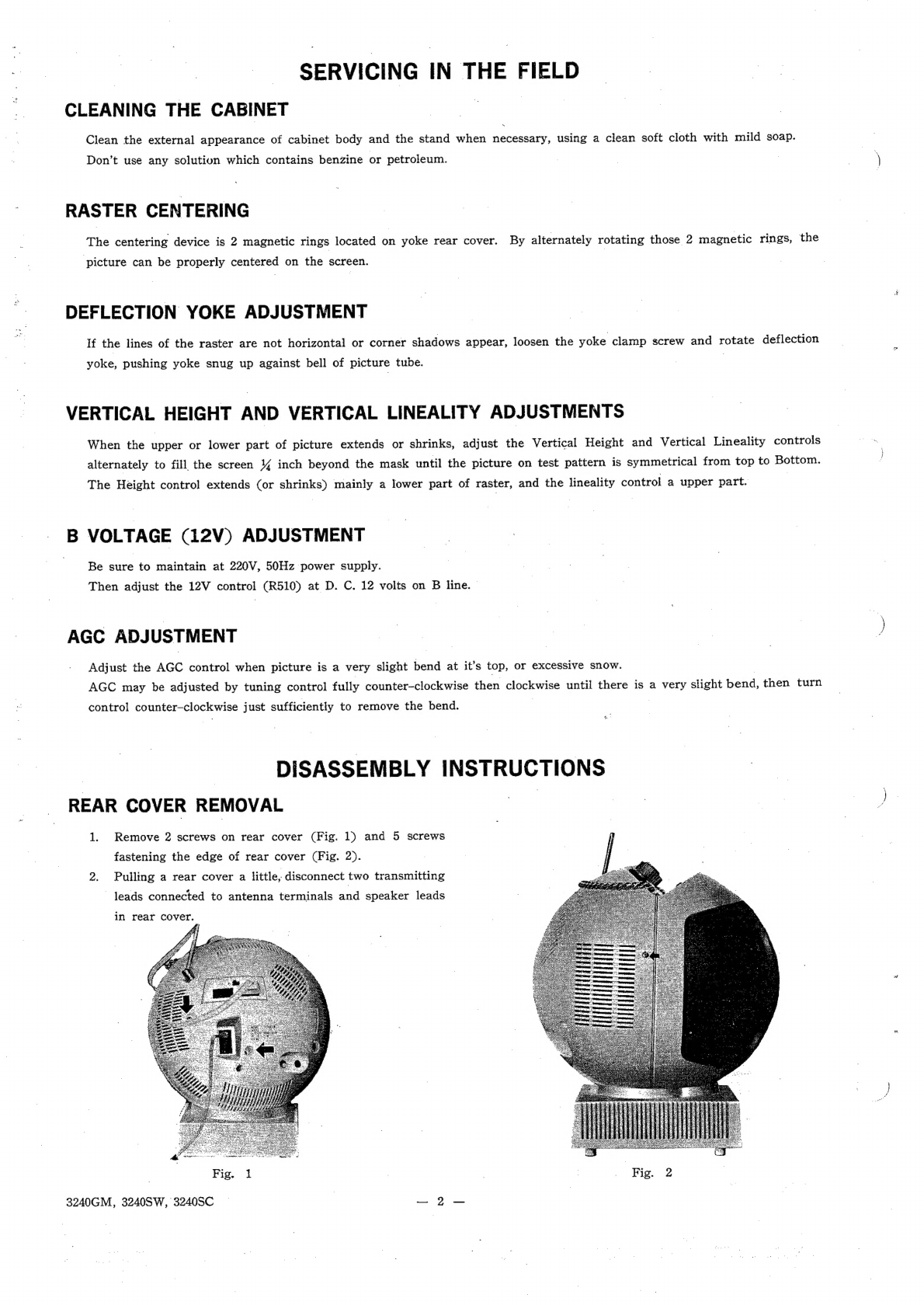
2
Table of contents
Other JVC TV Receiver manuals
Popular TV Receiver manuals by other brands

TerraTec
TerraTec Cinergy Hybrid T USB XS Hardware and driver Hardware and driver installation

Samsung
Samsung SP43J5HF3C/XTT Service manual

Cincinnati Bell
Cincinnati Bell Fioptics TV user guide

SuddenLink
SuddenLink TiVo Premiere user guide

Zenith
Zenith H2226R Service manual

Strong
Strong SRT 8525 user manual