TV-13142
TV-13142W
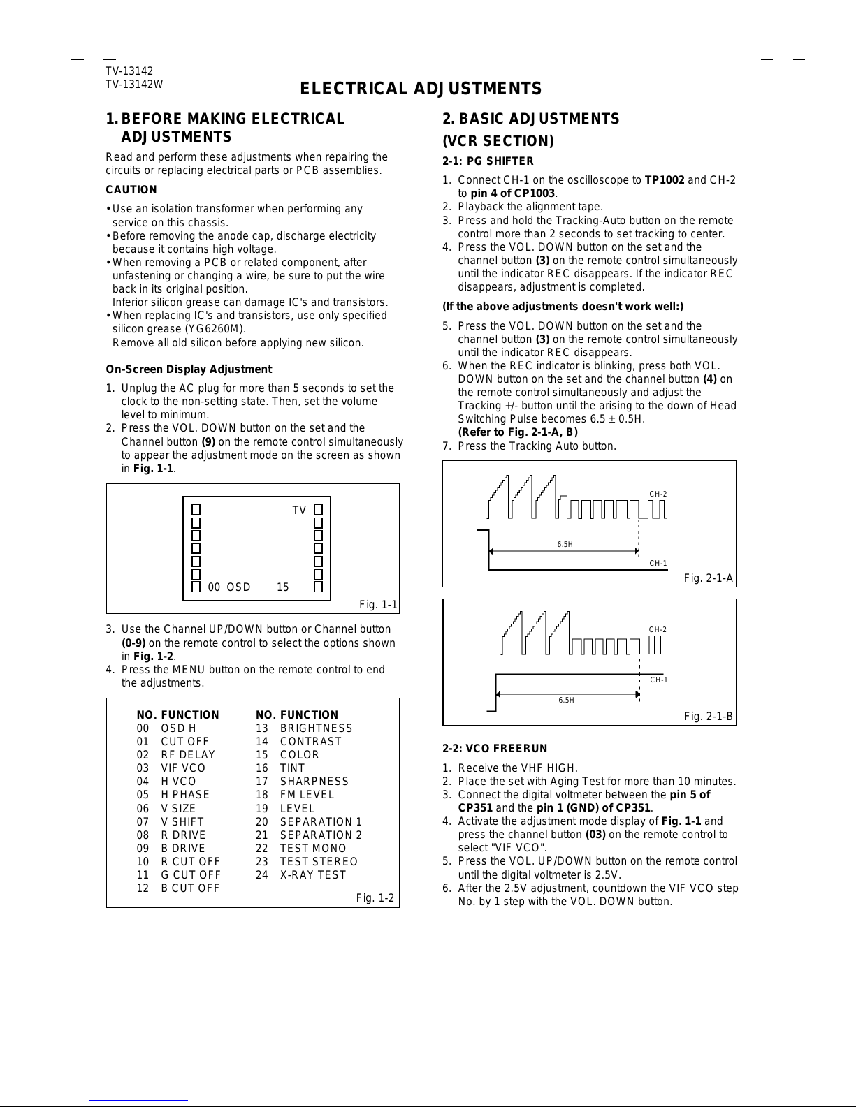
ELECTRICAL ADJUSTMENTS
2-3: RF AGC
1.
2.
3.
4.
Receive the VHF HIGH (63dB).
Connect the digital voltmeter between the pin 5 of
CP351 and the pin 1 (GND) of CP351.
Activate the adjustment mode display of Fig. 1-1 and
press the channel button (02) on the remote control to
select "RF DELAY".
Press the VOL. UP/DOWN button on the remote control
until the digital voltmeter is 2.9 ±0.1V.
(TV SECTION)
2-4: CONSTANT VOLTAGE
1.
2.
3.
4.
Connect the digital voltmeter to the TP601.
Set condition is AV MODE without signal.
Using the remote control, set the brightness and contrast
to normal position.
Adjust the VR502 until the digital voltmeter is 135 ±0.5V.
2-8: HORIZONTAL PHASE
1.
2.
3.
4.
Receive the center cross signal from the Pattern
Generator.
Using the remote control, set the brightness and
contrast to normal position.
Activate the adjustment mode display of Fig. 1-1 and
press the channel button (05) on the remote control to
select "H PHASE".
Press the VOL. UP/DOWN button on the remote
control until the right and left screen size of the vertical
line becomes the same.
1.
2.
3.
4.
5.
6.
Adjust the unit to the following settings.
R CUT OFF=128, G CUT OFF=128, B CUT OFF=128,
BRIGHTNESS=128, CONTRAST=100
Place the set with Aging Test for more than 15 minutes.
Set condition is AV MODE without signal.
Using the remote control, set the brightness and
contrast to normal position.
Activate the adjustment mode display of Fig. 1-1 and
press the channel button (01) on the remote control to
select "CUT OFF".
Adjust the Screen Volume until a dim raster is obtained.
2-5: CUT OFF
2-6: WHITE BALANCE
NOTE: Adjust after performing CUT OFF adjustment.
1.
2.
3.
4.
5.
6.
7.
8.
Place the set with Aging Test for more than 15 minutes.
Receive the color bar pattern.
Using the remote control, set the brightness and
contrast to normal position.
Activate the adjustment mode display of Fig. 1-1 and
press the channel button (10) on the remote control to
select "R CUT OFF".
Using the VOL. UP/DOWN button on the remote
control, adjust the R CUT OFF.
Press the CH. UP/DOWN button on the remote control
to select the "R DRIVE", "B DRIVE", "G CUT OFF" or
"B CUT OFF".
Using the VOL. UP/DOWN button on the remote
control, adjust the R DRIVE, B DRIVE, G CUT OFF or
B CUT OFF.
Perform the above adjustments 6 and 7 until the white
color is looked like a white.
2-7: FOCUS
1.
2.
3.
4.
Receive the monoscope pattern.
Using the remote control, set the brightness and
contrast to normal position.
Turn the Focus Volume fully counterclockwise once.
Adjust the Focus Volume until picture is distinct.
2-9: VERTICAL SHIFT
1.
2.
3.
4.
Receive the center cross signal from the Pattern
Generator.
Using the remote control, set the brightness and
contrast to normal position.
Activate the adjustment mode display of Fig. 1-1 and
press the channel button (07) on the remote control to
select "V SHIFT".
Press the VOL. UP/DOWN button on the remote
control until the horizontal line becomes fit to the notch
of the shadow mask.
2-10: VERTICAL SIZE
1.
2.
3.
4.
5.
Receive the cross hatch signal from the Pattern
Generator.
Using the remote control, set the brightness and
contrast to normal position.
Activate the adjustment mode display of Fig. 1-1 and
press the channel button (06) on the remote control to
select "V SIZE".
Press the VOL. UP/DOWN button on the remote
control until the rectangle on the center of the screen
becomes square.
Receive a broadcast and check if the picture is normal.
2-11: SUB BRIGHTNESS
1.
2.
3.
4.
5.
6.
Receive the monoscope pattern.
Using the remote control, set the brightness and
contrast to normal position.
Activate the adjustment mode display of Fig. 1-1 and
press the channel button (13) on the remote control to
select "BRIGHTNESS".
Press the VOL. UP/DOWN button on the remote
control until the white 10% is starting to be visible
Receive the monoscope pattern. (Audio Video Input)
Press the INPUT button on the remote control to set to
the AV mode. Then perform the above adjustments
2~4.
2-12: SUB CONTRAST
1.
2.
3.
4.
5.
Activate the adjustment mode display of Fig. 1-1 and
press the channel button (14) on the remote control to
select "CONTRAST".
Press the VOL. UP/DOWN button on the remote
control until the contrast step No. becomes "102"
Press the INPUT button on the remote control to set to
the AV mode.
Activate the adjustment mode display of Fig. 1-1 and
press the channel button (14) on the remote control.
Press the VOL. UP/DOWN button on the remote
control until the contrast step No. becomes "100"