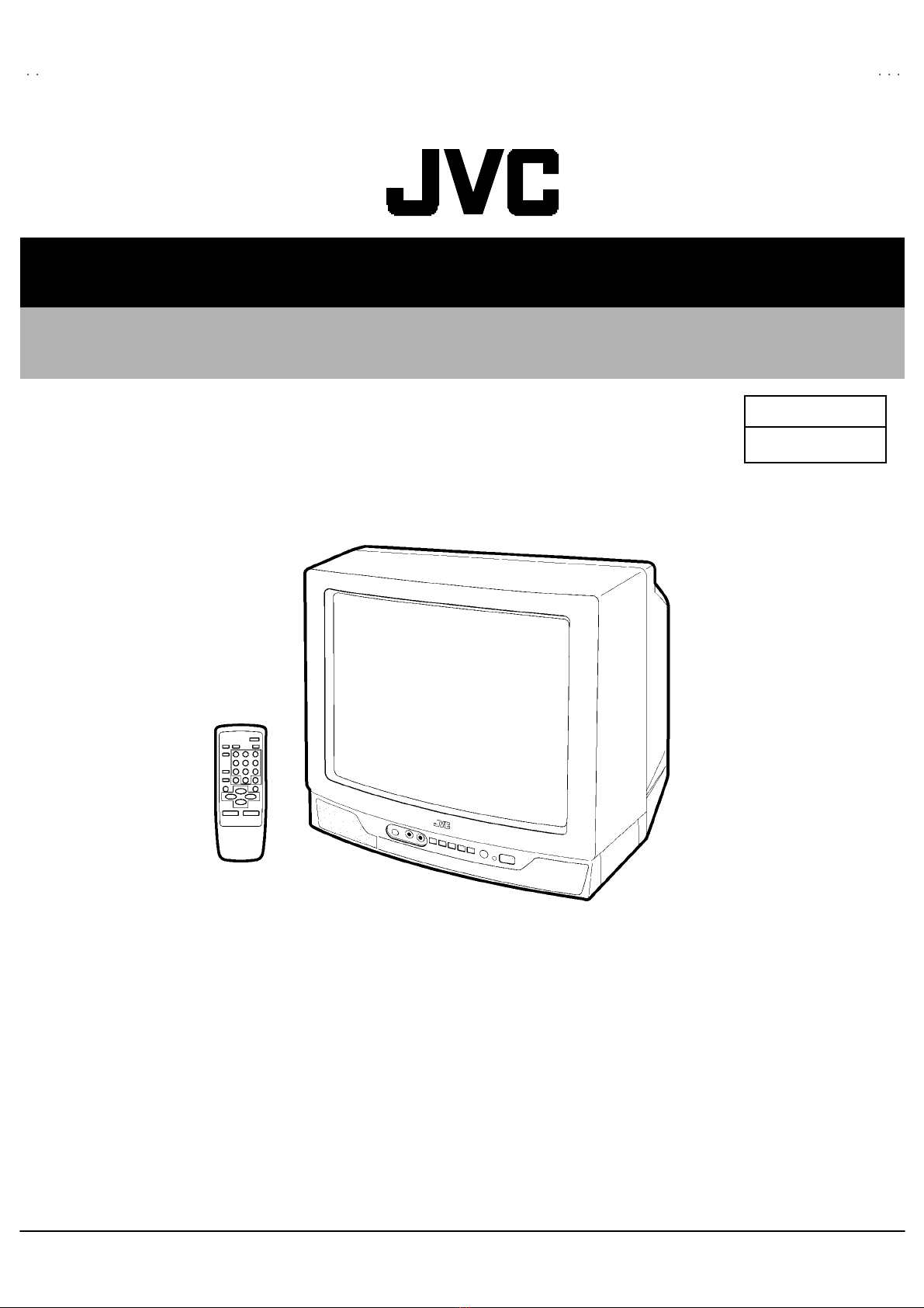
JVC AV-14A3, AV-14F3, AV-1435, AV- User manual

No.52029
Jul. 2002
AV-14A3
AV-1415E
E
AV-14AMG
3
1COPYRIGHT © 2002 VICTOR COMPANY OF JAPAN, LTD.
AV-14A3 / AV-14A3/AU
AV-14A3/HK / AV-1415EE
AV-14AMG3 / AV-14AMG3/-A
CONTENTS
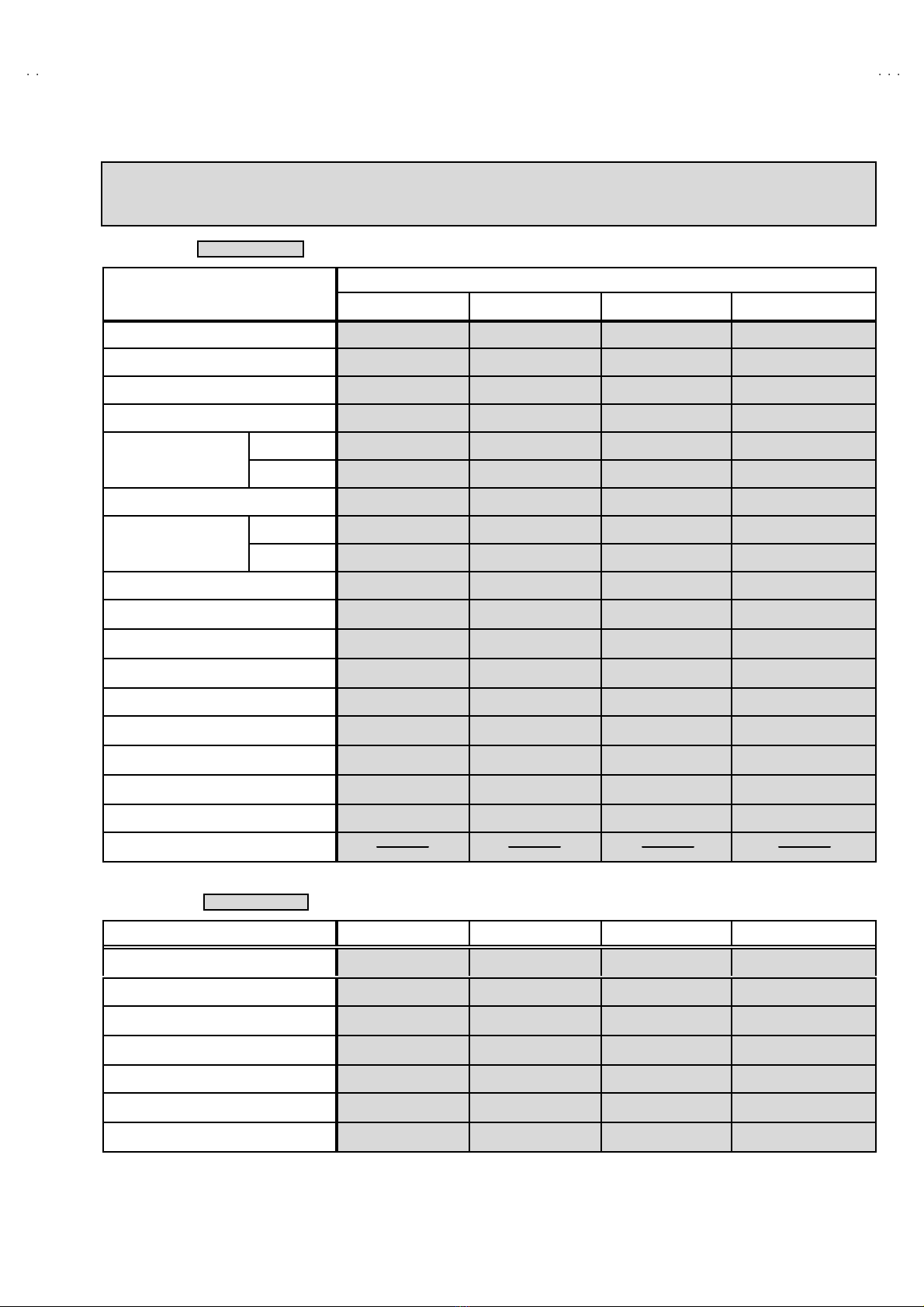
!SPECIFICATIONS ・・・・・・・・・・・・・・・・・・・・・・・・・・・・・・・・
・・・・・・・・・・・・・・・・・・・・・・・・・・・・・・・・・・・・・・・・・・・・・・・・・・・・・・・・・・・・・・・・
・・・・・・・・・・・・・・・・・・・・・・・・・・・・・・・・・・・・・・・・・・・・・・・・・・・・・・・・・・・・・
・・・・・・・・・・・・・・・・・・・・・・・・・・・・・・・・・・・・・・・・・・・・・・・・・・・・・・・・・・
・・・・・・・・・・・・・・・・・・・・・・・・・・・・・ 2
!SAFETY PRECAUT IONS ・・・・・・・・・・・・・・・・・・・・・・・・・・・・・・・・
・・・・・・・・・・・・・・・・・・・・・・・・・・・・・・・・・・・・・・・・・・・・・・・・・・・・・・・・・・・・・・・・
・・・・・・・・・・・・・・・・・・・・・・・・・・・・・・・・・・・・・・・・・・・・・・・・・・・・・・・
・・・・・・・・・・・・・・・・・・・・・・・・・・・・・・・・・・・・・・・・・・・・・・
・・・・・・・・・・・・・・・・・・・・・・・ 3
!FEATURES・・・・・・・・・・・・・・・・・・・・・・・・・・・・・・・・
・・・・・・・・・・・・・・・・・・・・・・・・・・・・・・・・・・・・・・・・・・・・・・・・・・・・・・・・・・・・・・・・
・・・・・・・・・・・・・・・・・・・・・・・・・・・・・・・・・・・・・・・・・・・・・・・・・・・・・・・・・・・・・・・・
・・・・・・・・・・・・・・・・・・・・・・・・・・・・・・・・・・・・・・・・・・・・・・・・・・・・・・・・・・・・・・・・
・・・・・・・・・・・・・・・・・・・・・・・・・・・・・・・・・・・
・・・・・・
・・・ 4
!FUNCTIONS ・・・・・・・・・・・・・・・・・・・・・・・・・・・・・・・・
・・・・・・・・・・・・・・・・・・・・・・・・・・・・・・・・・・・・・・・・・・・・・・・・・・・・・・・・・・・・・・・・
・・・・・・・・・・・・・・・・・・・・・・・・・・・・・・・・・・・・・・・・・・・・・・・・・・・・・・・・・・・・・・・・
・・・・・・・・・・・・・・・・・・・・・・・・・・・・・・・・・・・・・・・・・・・・・・・・・・・・・・・・・・・・・・・・
・・・・・・・・・・・・・・・・・・・・・・・・・・・・・・・・・・
・・・・
・・ 5
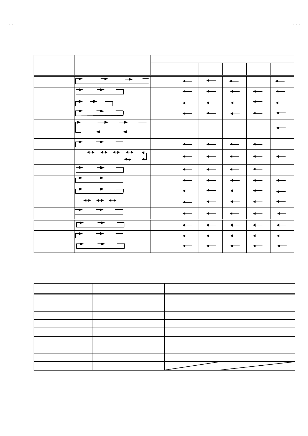
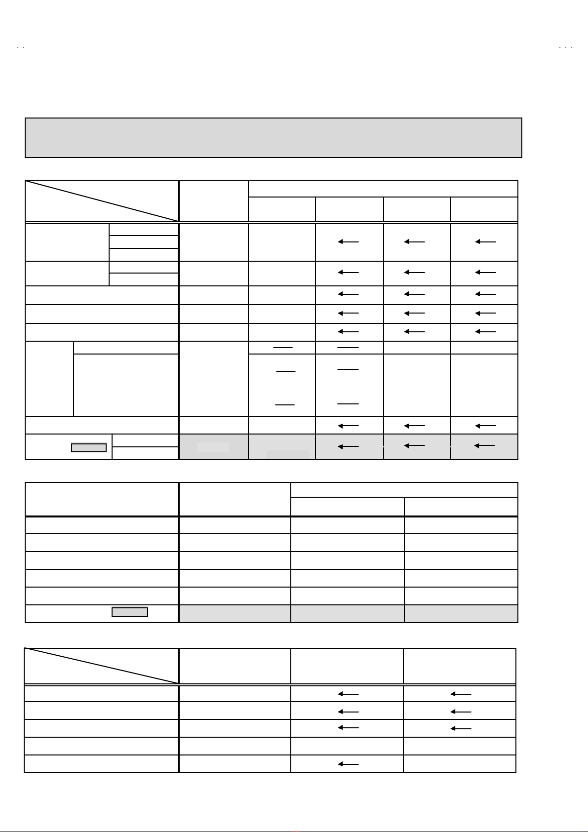
!MAIN DIFFERENCE LIST ・・・・・・・・・・・・・・・・・・・・・・・・・・・・・・・・
・・・・・・・・・・・・・・・・・・・・・・・・・・・・・・・・・・・・・・・・・・・・・・・・・・・・・・・・・・・・・・・・
・・・・・・・・・・・・・・・・・・・・・・・・・・・・・・・・・・・・・・・・・・・・・・・・・・・・・・・
・・・・・・・・・・・・・・・・・・・・・・・・・・・・・・・・・・・・・・・・・・・・・・
・・・・・・・・・・・・・・・・・・・・・・・ 7
!SPECIFIC SERVICE INSTRUCTIONS ・・・・・・・・・・・・・・・・・・・・・・・・・・・・・・・・
・・・・・・・・・・・・・・・・・・・・・・・・・・・・・・・・・・・・・・・・・・・・・・・・・・・・・・・・・・・・・・・・
・・・・・・・・・・・・・・・・・・・・・・・・・・・・・・・・・・・・・・・・・・・・・
・・・・・・・・・・・・・・・・・・・・・・・・・・
・・・・・・・・・・・・・ 8
!SERVICE ADJUSTMENTS ・・・・・・・・・・・・・・・・・・・・・・・・・・・・・・・・
・・・・・・・・・・・・・・・・・・・・・・・・・・・・・・・・・・・・・・・・・・・・・・・・・・・・・・・・・・・・・・・・
・・・・・・・・・・・・・・・・・・・・・・・・・・・・・・・・・・・・・・・・・・・・・・・・・・・・・
・・・・・・・・・・・・・・・・・・・・・・・・・・・・・・・・・・・・・・・・・・
・・・・・・・・・・・・・・・・・・・・・ 15
!PARTS LIST ・・・・・・・・・・・・・・・・・・・・・・・・・・・・・・・・
・・・・・・・・・・・・・・・・・・・・・・・・・・・・・・・・・・・・・・・・・・・・・・・・・・・・・・・・・・・・・・・・
・・・・・・・・・・・・・・・・・・・・・・・・・・・・・・・・・・・・・・・・・・・・・・・・・・・・・・・・・・・・・・・・
・・・・・・・・・・・・・・・・・・・・・・・・・・・・・・・・・・・・・・・・・・・・・・・・・・・・・・・・・・・・・・・・
・・・・・・・・・・・・・・・・・・・・・・・・・・・・・・・・・
・・
・33
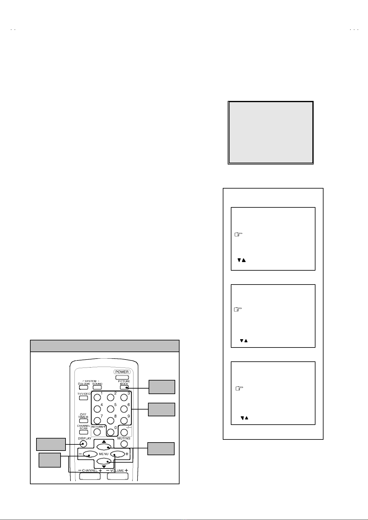
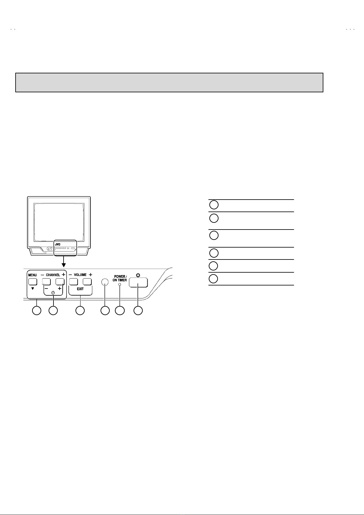
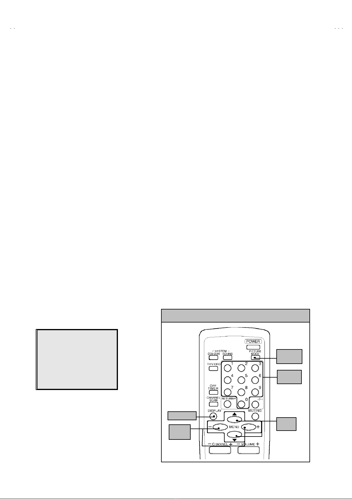
★OPERATING INSTRUCTIONS
★STANDARD CIRCUIT DIAGRAM ・・・・・・・・・・・・・・・・・・・・・・・・・・・・・・・・
・・・・・・・・・・・・・・・・・・・・・・・・・・・・・・・・・・・・・・・・・・・・・・・・・・・・・・・・・・・・・・・・
・・・・・・・・・・・・・・・・・・・・・・・・・・・・・・・・・・・・・・・・・・・・・・・・
・・・・・・・・・・・・・・・・・・・・・・・・・・・・・・・・
・・・・・・・・・・・・・・・・2-1
SERVICE MANUAL
COLOUR TELEVISION
BASIC CHASSIS
CG

No. 52029
A
V-14A3
A
V-1415EE
A
V-14AMG3
8
SPECIFIC SERVICE INSTRUCTIONS
DISASSEMBLY PROCEDURE
REMOVING THE REAR COVER
1. Unp lu g t he po we r plu g.
2. As sh own in f igure, remove t he 5screws marked !
!!
!an d a
screw marked "
""
".
3. W ithdr a w t he rear co ver to wa rd you .
[CAUTION]
"W hen rei nst al lin g th e r e ar cove r , c ar efu lly pus h it i nwar d af ter
inser tin g t he MA IN PW B i nt o th e r ea r cove r gr oo ve .
REMOVING THE MAIN PW BOARD
"After removing the rear cover.
1. Sl ight ly ra is e th e b ot h si de s of t he M AIN PW BOAR D b y han d
an d r e mo ve t he PW B stop per m ar ked #
##
#from the front cabinet.
2. W ithdr a w t he M AIN PW B OAR D b ackw ard.
( If n ecess ar y, ta ke off the wir e cl amp, c onn ect or s etc. )
REMOVING THE SPEAKER
"After removing the rear cover.
1. By holding up t he SP EAK ER HOLDER mar ked $
$$
$slightly and
un locking th e claw, t he SP EAK ER HOL DE R can b e r emoved .
The n yo u c an r e mo ve t he SPE AKE R.
CHECKIN G THE MAIN PW BOARD
1. To ch eck the ba ck si de of th e PW B oar d.
1) Pu ll out the MA IN PW Bo ard. ( Ref er to RE MO VIN G TH E M AIN
PW B oard)
2) Er ect th e PW Boar d ve rt ic al ly so th at you ca n easi ly ch eck th e
b ack si de of th e PW B oar d.
[CAUTION]
"W hen e re cting th e PW Boar d, be car ef ul s o t hat th er e w il l b e n o
con tact in g with ot her PW Boar d.
"Before turning on power, make sure that the CRT earth wire and
oth er co nne cto r ar e p r ope rl y c onn ect ed.
WIRE CLAMPIN G AND C ABLE TYING
1. Be sure t o clamp the wire.
2. Never r emo ve th e c able ti e use d f or tying th e w ire s to ge the r.
Sh oul d i t be inad ver te ntly r em ove d, b e su re to tie th e wi res wit h a
new cable tie.

No. 52029
A
V-14A3
A
V-1415EE
A
V-14AMG3
10
REPLACEMENT OF MEMORY ICs
1. MEMORY ICs
Thi s mod el u ses me mo ry I Cs. Thi s me mo r y IC da ta ar e f or pr o per oper a ti on of th e vide o a nd d eflect io n ci rcuits.
W hen r ep la ci ng me mory ICs, b e su re to us e ICs wr it ten w ith t he initial va lu es of dat a.
2. PROCEDURE FOR REPLACING MEMORY IC s
(1) Power off
Sw itch the p ow er of f an d di sco nn ect t he pow e r plu g f rom t he wall out l et.
(2) Replace ICs
Be sure to use memory ICs written with the initial data values.
(3) Power on
Con nect th e p ow er pl u g i nt o t he wall ou tlet and sw itch t he po we r on .
(4) Check and set SY STEM CONSTANT SET
・
・・
・It must not adjust without adjustment signals.
1) Press t he DI SPLAY ke y and th e PICTURE MODE key of the REMOTE
CONTROL UNIT simultaneously.
2) The SERVICE MENU screen of Fig. 1 will be displayed.
3) W hil e th e SE RV IC E M ENU i s di spl ayed , ag ai n pr ess the DI SPLAY key and
PICTURE MODE ke y si mul ta neo usl y, an d t he S YST EM C ON STA NT SE T
scr een of F ig. 2 will b e di spl a ye d.
4) Check th e se tting va l ues of the S YSTE M CON S TANT SE T of Tab l e 1. If the
value is diff erent, se lect th e s etting item with the MENU ▼/▲key, and s et
th e co rrect valu e w ith t he MENU- / + k ey.
5) Press the DI SPLAY ke y twi ce, and r etu rn t o th e n or mal scr ee n.
(5) Receive channel of setting
Refer to the OPE RATI NG I NST RUCTIONS an d set th e r ece ive cha nn els
( chan ne ls pr ese t) as descr ibe d
(6) User Setting
Check t he us er s ettin g val u e of Tab le 2, a nd if se tting val ue is di f fer en t, set
th e co rrect valu e.
For setting, refer to the OPE RATI NG INSTRUCTIO NS .
(7) Setting of SERVICE MENU
Ve rif y the set ting it ems of th e SE RVICE MEN U, and r eset w he re n ecessa r y.
For setting, refer to the SERVICE ADJUSTMENTS.
S
ERVI
C
E MEN
U
1.IF 2.V
/C
3.DEF 4.VSM PRESET
5.PRESET
6.SETUP TOUR OFF
1-6 SELECT DISP :EXIT
******
************
****** *****
**********
***** **
****
**
.
***
******
***
*** ** **
*** ** ***** ** **
*** ** ** ** ***
** ***** ***
** ***
Fig.1
Fig.2
SY STEM CONSTANT- Ⅰ
ⅠⅠ
Ⅰ
CO
L
OU
R:
BI LIN G UAL : N O
TUNE R : MU
ECO SENSOR : YES
L ANGU AGE :
SYSTEM CONSTANT SE T 1
***
***
: SELECT
- / + : OPERATE DISP : EX IT
/
SY STEM CONSTANT- Ⅱ
ⅡⅡ
Ⅱ
B/B SOUND :
LOCK : 180
COL OUR AU T O :
QSS : MINT
ALC : NO
TEXT RATE : 2 0
SYSTEM CONSTANT SE T 2
***
:
S
EL -
/
+ :
O
PE DI
S
P : E XIT/
***
SY STEM CONSTANT- Ⅲ
ⅢⅢ
Ⅲ
AMP T
U
NER : N
O
VNR : YES
TEXT TABLE : CYL
VOLUM PWM : POS
SYSTEM CONSTANT SET 3
: SEL -/ + :OPE DISP: EXIT/
KEY ASSIGNMENT OF REMOTE CONTROL UNIT
MENU
▼/▲key
MENU
-/+key
DI SP LA Y k e y
PICT URE
MO D E ke y
NUMBERS
key

No. 52029
A
V-14A3
A
V-1415EE
A
V-14AMG
3
11
SE TTING OF SY STEM C ONSTANT SET
Setting value
Setting item Setting contents AV-
14A3
AV-
14A3/AU
AV-
14A3/HK
AV-
1415EE
AV-
14AMG3
AV-
14AMG3/-A
COLOUR TRIPLE MULTI.
BILINGUAL NO
TUNER MU
AI ECO S ENSOR NO
LA NG UA GE E/R E/C/ M/I E/C E/R/U E/R/A /P
B/B SOUND OFF ON
LO CK
YES 10 20
~230
250 240 18 0
COLOUR AUTO NO YE S
QSS MI NT
ALC NO
TEXT RA TE 10 20 40 80 20
AMP TUNER NO
VNR YE S
TEXT TABLE CYL
VOL UM PW M POS
Table 1
US ER SE TTING V ALUES
Setting item Setting value Setting item Setting value
SUB POWER ON LANGUAGE ENGLISH
CHA NNE L PO SITIO N 1 PO SITIO N CHA NNE L P RE SET Refe r t o OPE RATING I NS TRUCTION
VOL UME Ab out 10 SE TUP TOU R ON
TV/VIDEO TV VNR OFF
ON SCREEN DI SPLAY POS ITION INDICATIO N AUTO S HUTOFF OFF
COLOUR SYSTEM PAL ON TIMER PR1 0:00
SOUND SYSTEM B / G BLUE BACK OFF
OFF TIMER OFF OSD.Shows 00 CHILD LOCK OFF
PICTURE MODE (VSM) BRIGHT
Table 2
YE S NO
ON OFF
YE S NO
MI NT MQ SS
YE S NO
YE S NO
YE S NO
A
RA CYL
MU MA
E/R/A /P
MUL T I. PA LTRIPLE
POS NEG
E/C/ M/I
YE S NO
E/C E/R
E/R/U

No. 52029
A
V-14A3
A
V-1415EE
A
V-14AMG3
12
INITIAL SETTING VALUE OF SERVICE MENU
1. Ad justment of the SE RVICE MENU is m ade on the bas is of the initial s etti ng values ; howev er, the new se tting va lues w hi ch
set the screen in its optimum condition may differ from the initial setting.
2. Do no t change the initial Setting Values of the Setting (Adjustment) items not listed In “ADJUSTMENT”.
2. V/C
Initial setting v al ue
Colou r sy st em
Setting item
Va riabl e
range PA L SE C AM NT SC 3.5 8 NT SC 4.4 3
RED
GREEN1. CUT OFF
BL UE
- 128 ~+127 -50
RED
2. DRI VE BL UE - 128 ~+127 0
3. BR IG HT -127~+127 0
4. CONT . -63 ~+63 0
5. COLOUR -63 ~+63 0
TV 00
AV -1 4A3
AV -1 4A3 /AU
AV -1 4A3 /HK
AV -1 41 5EE
00
6. TINT VI DE O
AV -1 4A MG3
AV -1 4A MG3 /-A
-63 ~+63
+5 0
7. SECAM BL ADJ. -31 ~+31 0
TV -17
(
Fixed
)
8. SHARP Do Not Adj.
VI DE O
-32~+31
+10
(
Fixed
)
3. DE FLECTION
Initial setting v al ue
Setting item Variable range
fv : 50Hz MODE fv : 60Hz MODE
1. VER. POS ITION -04 ~+03 0 - 3
2. HOR. POSITION -16 ~+15 +1 + 4
3. VER. HE IGHT -64 ~+63 -20 - 2
4. VER . L INE AR IT Y -32 ~+31 +15 0
5. VER. SWCURVE -32 ~+31 -32 0
6. H OR. VC O AD J UST Do No t Ad j. -63 ~+62 0 0
4. VS M PRE SE T
VS M
p
r ese t
VSM mode
Setting item
BRIGHT STANDARD SOFT
TINT SE TTING VA LUE +1 5
COLOUR SE TTING VA LUE +15
BR IG HT SE TTING VA LUE +1 5
CONT. SE TTING VA LUE +30 + 15 +13
SHARP SE TTING VA LUE +1 5 +1 2

No. 52029
A
V-14A3
A
V-1415EE
A
V-14AMG
3
13
5. PRESE T
The items in the following table, it is no requirem ent for adjustment.
If values had changed by the mi ss operati on, set the initial setting v alues i n the fol lowing table .
Colou r Sy stem Do No t Ad ju st
Initial setting value (Fixed value)
Setting item
PA L SE C AM NT SC 3.5 8 NT SC 4.4 3
1. C TRAP FIX 1 1 1 1
2. SHARP PEAK 0 0 0 0
3. ABL 1 1 1 1
4. GAMMA 0 0 0 0
TV 0 2 2 3
5. Y. DELAY TIME
VI DE O 0 2 0 2
6. BL ACK EX P START +3+3+3+3
TV 1 1 0 0
7. C-BPF
VI DE O 1 1 1 1
8. CW / SCP 0 0 0 0
9. VIF DET LEVEL 0 0 0 0
11. IF AGC MIN 0 0 0 0
12 . VIF AGC 0 0 0 0
13. VIF PMOD 0 0 0 0
19 . VN R 15 15 15 15
20 . RGB LIM 1 1 1 1
21. RGB LIMIT LEVEL 2 2 2 2
23. TEXT H. POS ITION -3 -3 -3 -3
24. READ DATA
Sound System D o No t Ad ju s t
Setting item B/G I D/K M
10. SIF DET LEVEL +0+0+0+0
14. SIF BPF BW ADJUST +0+0+0+0
15. SIF TRAP FO ADJUST +0+0+0+0
16. SIF TRAP FO ADJUST 2 +0+0+0+0
17. SIF -TRAP 0 0 0 0
18. SIF -BPF 1 0 0 0
22 . SIF S W 0 1 1 1

No. 52029
A
V-14A3
A
V-1415EE
A
V-14AMG3
14
REPLACEMENT OF IC301 (IF V/C DECODER)
"For the I C301(I F V/C DECODER) of this model, a ll data are written in the micro-computer. So, wri te the data i n the micro-
computer in accordance with the following procedures before starting adjustment.
PROCEDURES
(1) Turn t he POW ER O FF.
(2) R ep lace t he IC30 1 wi th a n ew o ne .
(3) W hi le pr essing ME NU bu tto n a nd VO L+ bu tto n ON the FRO NT CABINE T s imul t ane ous ly, t ur n th e POW ER O N. W h en th e POW ER is
turned ON, th e d at a is writ ten in t he m icro-comp ute r imm ed iately.
LOCATIONS OF FRONT PANEL BUTTONS AND LAM PS
MENUbuttons
CHANNEL ・/ ・buttons
(ME NU ・/ ・bu tt ons)
VOLUME
-/+buttons
(MENU -/+bu tto ns)
AI ECOsensor
REMOTE CONTROL sens or
ON TIMER lamp
POWERlamp
MAIN POW ER button
MENUbuttons
CHANNEL -/+buttons
(ME NU -/+buttons)
VOLUME -/+buttons
(MENU -/+bu tto ns)
REMOTE CONTROL sens or
POWER/ ONTIMERlamp
MAIN POWER butt on
1
2
3
4
5
6
12 345 6

No. 52029
A
V-14A3
A
V-1415EE
A
V-14AMG
3
15
SERVICE ADJUSTMENTS
BEFORE STARTING SERVICE ADJUSTMENT
1. There ar e 2 w ay of adjus ti ng t hi s TV: One i s wi th t he
REMOTE CONTROL UNIT and the other is the conventional
method using adjustment parts and components.
2. The adjustment with the REMOTE CONTROL UNIT is made
on the basis of the initial setting v alues. The setting values
which adjust the screen to its optimum condition may differ
from the initial s etti ng v al ues.
3. Make s ure th at conn ect ion is c orrect ly ma de t o AC p ower
sourc e.
4. Tur n on t he p ower of th e se t an d eq uipm en t bef or e us e, an d
sta rt t he ad ju stm en t pr oc edur e s af ter waiti n g at l east 30 min ute s.
5. Unless ot her wise spec if i ed, p r ep are th e mo st suita ble r ec eptio n
or i np ut si gn al for adj ust m ent.
6. Nev er t ouc h a ny adju s tme nt part s, whi ch ar e no t spe cif ied
in t he li st f or thi s adjust me nt VRs , tra nsf or ms, c onde nser s,
etc.
7. Pr ep aratio n f or ad j ustm en t
Unless otherwise specified in the adjustment instructions, preset
the following functions with the REMOTE CONTROL UNIT.
User mode position
PICTURE MODE (VSM) BRIGHT
VNR OFF
TINT / COLOUR / BRIG HT
CONT. / SHARP CENTER
BL UE BA CK OFF
OFF TIMER OFF
AUTO SHUT OFF OFF
MEASURING INSTRUMENT AND FIXTURES
1.DC voltmeter (or digital voltmeter)
2.Oscilloscope
3. Sign al g en er at or (P att er n g en er at or) [ PAL / S EC AM / N TS C]
4.Remote control unit
ADJUSTMENT ITEMS
Ad justment item Ad justment item
B1 POWE R SUPPL Y DEFLECTION c ircuit adjustment
FOCUS adjustment VSM PRESET s etting
IF circ uit a djust ment PURITY/ CO NV ERGENCE adjus tment
V/C (Video / Chroma) circuit adjustment

No. 52029
A
V-14A3
A
V-1415EE
A
V-14AMG3
16
BASIC OPERATION OF SERVICE MENU
"The adjustment using SERVICE MENU
The f ollowing adjus tme nt it ems u se t he SE RV ICE MENU in th e series of the adju stment . The ad justment s ar e m ade on the bas is of the
initial se tti ng val u es. Th e ad ju stm ent val u es whi ch ad ju st t he scr een to th e o ptim um co ndi t io n c an b e diffe re nt from th e i n iti a l sett in g va l ues.
W ith th e S ER VIC E ME NU, var ious s ett in gs c an be m ade , a nd the y ar e br oa dly cl assifi e d i n th e f ollo win g i te ms of s ettin gs.
1.I F ・・・・・・・ ・・・・・・・・・・・・・ ・・・ Adjustment of the IF circuits.
2.V /C ・・・・・・・ ・・・・・・・・・・・・・ ・・ Ad ju stm en t of th e VIDEO /CHRO MA ci rcui t.
3.DEF ・・・・・・・ ・・・・・・・・・・・・・ ・ Adjustment of the DEFLECTION circ uit.
4.V SM PRES ET ・・・・・・・ ・・・・・ Ad ju stm en t of th e ini t ia l sett in g va lue s of VSM co nd it i on as STA N DA RD, SOFT a nd BR IGHT .
(VSM : Video Status Memory)
5.PRESET ・・・・・・・ ・・・・・・・・・・ Adjustment of the RF circ uit [Do not adjust].
6. SETUP TOUR OFF ・・・・・・・ It s hould b e able to select mode (LANGUAG E and AUTO CH PRESE T)..
[Shou ld be O FF].
"Key operation of the SERVICE MENU
[Enter to SERVICE MENU]
Press the DI SPLAY key and t he PICTURE MODE key of the REMOTE CONTROL
UNI T si mu lt an eou sl y. Th en ent er th e S ERVIC E ME N U m od e as sh ow n in Fig.1 .
[Exit from SERVICE MENU]
W hen co m plete th e ad j ust me nt w ork, press th e DI SPLAY key to return t o the
SERVICE MENU.
An d th en pr ess th e DI SPLAY ke y ag ai n, r etur n to th e n or m al scr een .
[ Se lec t fro m SE R VIC E M E NU ]
In SERVI CE M ENU, pr ess t he n umber (1 ~6) ke y of th e r em o te c ont ro l un it , to se l ect
an y of th e ad j ustm en t i te ms.
The colo ur s which se le cte d ite m ch ar act ers a r e ch ang ed .
SE RV ICE M ENU
S
ERVI
C
E MEN
U
1.IF 2.V/C
3.DEF 4.VSM PRESET
5.PRESET
6.SETUP TOUR OFF
1-6 SELECT DISP :EXIT
******
************
***********
**********
***** **
****
**
.
***
******
***
*** ** **
*** ** ***** ** **
*** ** ** ** ***
** ***** ***
** ***
Fig.1
KEY ASSIGNMENT OF REMOTE CONTROL UNIT
MENU
▼/▲key
MENU
-/+key
DI SP LA Y k e y
PICT URE
MO D E ke y
NUMBERS
key

No. 52029
A
V-14A3
A
V-1415EE
A
V-14AMG
3
17
[Method of setting]
1. IF
[1. VCO]
①1 K ey ・・・・・・・ ・・・・・・・・・・・・・ ・・・・・ Select 1.IF.
②1 K ey ・・・・・・・ ・・・・・・・・・・・・・ ・・・・・ Select 1.VCO
③The VCO (CW) screen will be displayed a allow mark when the AFC voltage is at a certain level.
④DISP LA Y K ey・・・・・・・ ・・・・・・・・・・・ As you press t his key twice, you will return to the SE RVICE M E NU.
[2. DELAY POINT]
①1 K ey・・・・・・・ ・・・・・・・・・・・・・ ・・・・・ Select 1.IF.
②2 K ey・・・・・・・ ・・・・・・・・・・・・・ ・・・・・ Se lect 2.DELAY P OINT.
③ME NU - /+ K ey ・・・・・・・ ・・・・・・・・・・ Set (adjust) the setting values of the s etting items.
④DISPLAYKey・・・・・・・ ・・・・・・・・・・・ W hen th is is presse d t wice, you will ret ur n t o t he SE RV ICE MEN U.
2.V /C, 3.DEF an d 4 .V SM PRES ET
①2~4Key ・・・・・・・ ・・・・・・・・・・・・・ ・・・ Select one from 2. V/C, 3. DE F an d 4. VSM PRE SET.
②MENU ▼/▲Key ・・・・・・・ ・・・・・・・ Select s etting items.
③MENU-/+ Key ・・・・・・・ ・・・・・・・・・・ Adj u st th e va l ues of t he i tem s.
④DISP LA Y K ey ・・・・・・・ ・・・・・・・・・・・ W hen th is is pr esse d, r e tur n t o t he SE R VICE MENU.
6.SE TUP TOUR
①B y p ressing th e 6 key, you can ch ang e t he ON or OFF ( should be OFF).
(ShouldbeOFF)
%・If it is ON, th en you tu rn th e TV po we r off , wh en you ar e t ur n t he TV p ow er o n a ga in .
The JVC’s logo will be shown about 15 s econds automatically.
②MENU -/+ Key ・・・・・・・ ・・・・・・・・・・ Select Language.
③MENU ▼Key・・・・・・・ ・・・・・・・・・・ Au to Se arch.

No. 52029
A
V-14A3
A
V-1415EE
A
V-14AMG3
18
SERVICE MENU FLOW CHART
S
ERVI
C
E MEN
U
1.IF 2.V/C
3.DEF 4.VSMPRESET
5.PRESET
6
.
S
ET
U
P T
OU
R
O
FF
1-6 SELECT DISP : EXI T
******
************
***********
**********
***** **
* ** *
* *
.
****
********
****
*** ** **
*** ** ***** ** **
*** ** **** ***
** ***** ***
** ***
SE RV ICE M ENU
IF
1. VCO
2. DELAY POI NT
1-2 :
S
ELE
C
T DI
S
P : E XI T
SU B M E NU 1. I F
VCO(CW)
***.**
MH z
T
OO
HI
G
H
ABOVE REFERENCE
JUST REFERENCE
BELOW REFERENCE
TOO LOW
AFT AD
JUS
T
** *(* *)
** *(* *)** *(* *)
** *(* *)
VCO ADJUST
** *(* *)
** *(* *)** *(* *)
** *(* *)
FINE
DISP : EXI T
DELAYPOINT UHF
AGC T AKE- OVER
**
- / + : OPERATE DISP: EXIT
6
.
S
ET
U
P T
OU
R
O
N
/
OFF
(By pressing 6- ke y)
BRIGHT
TINT
COLOUR
BRIGHT
CONT.
SHARP
-
/
+ :
O
PERATE DI
S
P : EXIT
**
**
**
**
**
SUB ME NU 4. V SM PRES ET
/ :SELECT
DEF
- / + : OPERATE DISP :EXIT
**
SU B M E NU 3. D EF
/ :SELECT
50
Hz
1. VER. POSITION
PAL
V/C PAL
1. CUTOFF
- / + : OPERATE DISP :EXIT
(
R
)
* **
(G)
* **
(B)
* **
50Hz
SU B M E NU 2. V /C
/ :SELECT
PRESET
1.
C
-TRAP FI X
- / + : OPERATE DISP :EXIT
*
50
Hz
SUB ME NU 5. P RE SET
/ :SELECT
B
/
K
PAL
O
FF

No. 52029
A
V-14A3
A
V-1415EE
A
V-14AMG
3
19
ADJUSTMENT LOCATIONS
TP- E
T
TP-47G
E
1
TP-47BTP-47R
U
T
1Pin TP-91(B1)
2Pin NC
3Pin X-ray1
4Pin X-ray2
5Pin TP-E
FBT
S1HV
MEMORY
IC
IC702
CH -
MENU
CH +
VOL-
VOL+
F901
DEG
TU001
UPPER : FOCUS
LOWER : SCREEN
IC301
15
U
PW
S901
IC701
S
S
CN001
MAIN PWB
CRT SOCKET PWB ( SOL DE R SI DE)
(W ithin MAIN PWB)
FRONT
TOP
CRT Earth wire

No. 52029
A
V-14A3
A
V-1415EE
A
V-14AMG3
20
ADJUSTMENTS
B1 POWER SUPPLY
Item Measuring
instrument Test point Ad justment part Description
Check of
B1 Power
Supply
Signal
generator
DC Vo lt -
meter
TP-91 ( B1)
TP-E (#
##
#)
1. Inp ut a wh ol e bl ack sig na l.
2. Connect a DC voltmeter to TP-91(B1) and TP-E (#).
3. M ake sur e t hat th e volt ag e i s DC 1 16. 5±2.0 V.
FOCUS ADJUSTMENT
Item Measuring
instrument Test point Ad justment part Description
Ad ju st men t
of FOCUS
Signal
generator
FOCUS VR
[In HVT]
1. Input a cross-hatch signal.
2. While watching the screen, adjust the FOCUS VR to make the
ver tical and ho rizo nta l l in es as f in e a nd sha rp as possi b le.
3. M ake sur e t hat w he n th e s cre en i s d ar ken ed, th e l ines r emain in
g ood focu s.
IF CIRCUIT ADJUSTMENT
Item Measuring
instrument Test point Ad justment part Description
●Please use signal generator which is correct proof about the
sen ding freq ue ncy.
Ad ju st men t
of VCO
(
CW
)
Signal
generator
Remote
control unit
1. VCO
1. Inp ut th e PA L f ul l col o ur b ar (2 10 .2 5MHz) sig nal .
2. En ter the SER VICE ME NU.
3. Sele ct 1 .IF f rom t he SERV ICE MENU.
4. Press 1 key and select 1. VCO.
5. Select VCO ADJ US T with MENU ▲/▼key.
6. Press MENU -/+ key until the colour of the characters TO O
HIGH ch an ges b lu e to ye l lo w . Th en g r ad ually pr ess th e MEN U
- /+ key u ntil th e TOO LOW ch ang es ye llow . At this t ime, conf irm
th at t he valu e of VCO ADJUST is n ear + 00 .
7. Select AFT ADJUS T with MENU ▲/▼key.
8. Press MENU -/+ key until the characters JUST REFERENCE
ch ang es b l ue to yel low .
9. Press the DI SPLAY key three times to return to normal screen.
VCO (CW)
***.**
MHz
TOO HIGH
AB OVE REFEREN CE
JU ST REF ER ENCE
BELOW R EFEREN CE
TOO LOW
AF T AD JUST
** *(* *)
** *(* *)** *(* *)
** *(* *)
VCO ADJUST
** *(* *)
** *(* *)** *(* *)
** *(* *)
FINE
DISP :EXIT
YE LLOW
D
o
n
ot
adjust
ADJUST MENT AT T HIS POINT IS USE LES S
AB
O
VEREFEREN
C
E
TOO HIGH
B ELO W RE F E RE NC E
J US T R EFE RE NC E
TOO LOW
ADJUSTMENT POINT

No. 52029
A
V-14A3
A
V-1415EE
A
V-14AMG
3
21
Item Measuring
instrument Test point Ad justment part Description
Ad ju st men t
of DELAY
POI NT
(AGC)
Signal
generator
Remote
control unit
DE LAY POINT
(AGC TAKE-OVER)
1. Inp ut a blac k an d wh it e sign al ( colo ur of f) .
2. En ter the SER VICE ME NU.
3. Select 1. IF f rom t he SERVI CE MENU.
4. Select 2. DELAY P OINT b y pr essin g th e 2key on the remote
control unit.
5. Set the set tin
g
valu es of th e set tin
g
item s as s ho wn bel lo w t abl e .
6. Then adjust the MENU - / + key until video noise disappears.
7. Tur n to oth er ch an nel s and make su r e th at the re ar e n o
irregularities.
Sett ing Ite m Variabl e ra nge Initial set ting v alue
SA MS UNG
(
QAU0246-002
)
MA TSUSITA
(
QAU0287-001
)
NT SC 3.5 8
45 45
DE LAY POINT
(AGC TAKE OVER) OTHER
0~127
35 35
DELAY POINT UHF
AGC TA KE-OVER
**
- / + :OPERATE DISP : EXIT

No. 52029
A
V-14A3
A
V-1415EE
A
V-14AMG3
22
VIDEO / CHROMA CIRCU IT ADJUSTMENT
The setting (adjustment) usin g the REMOTE CONTROL UNIT is made on the basis of the initial setting values.
The setting values which adjust the screen to the optimum condition can be different from the initial setting valu es.
Do not change the initial setting v alues of the setting items not listed in “ADJ USTMENT”.
Item Measuring
instrument Test point Ad justment part Description
Ad ju st men t
of WHITE
BALANCE
(Low light)
Signal
generator
Remote
control unit
1. CUT OFF (R)
CUT OFF (G)
CUT OFF (B)
SCREENVR
[IN HVT]
1. Inp ut a blac k an d wh it e sign al ( colo ur of f) .
2. En ter the SER VICE ME NU.
3. Select 2. V/C from the S ERVICE MENU, then selec t 1 . CUT OFF
(R), (G) and (B) .
4. Set each value to initial setting value with 4~9 keys of the
remote control unit.
5. Press the 1key of th e re mo te co ntr ol un i t to sh ow th e sin gle
horizontal line on screen.
6. Tur n t he SCREEN VR fully counter-clockwise, then slowly turn it
clockw is e to wh er e on e of a r ed , bl u e or gr e en co lour is f aint l y
vis ible.
7. Use keys 4~9of th e r emote c ontr o l u nit an d ad ju st the oth er 2
colo ur s wh i ch e xcep t th e ap pea r ed colo ur to w he re th e sin gle
h orizo nt al lin e app ea rs wh it e.
8. Turn the SCREEN VR to wh er e t he si n gle h or iz ont al lin e g l ows
fain tly.
9. Press the 2key to turn off th e single horizontal line.
10. Press the DI SPLAY key t wice to return to th e normal screen.
Ad ju st men t
of WHITE
BALANCE
(High light)
Signal
generator
Remote
control unit
2. DRI VE
(R)
DRI VE (B)
1. Inp ut a blac k an d wh it e sign al ( colo ur of f) .
2. En ter the SER VICE ME NU.
3. Select 2. V/C from the S ERVICE MENU.
4. Select 2. DRIVE (R) / (B) with MENU ▼/▲key, and set each
valu e t o initial s etting valu e with 4 and 7 or 6 an d 9 keys of th e
remote control unit.
5. Use the keys 4and 7 or 6and 9t o p ro duc e a w hite scr een
6. Press the DI SPLAY key t wice to return to th e nomal screen.
Ad justment item Va riabl e
range
Initial setting
value
R- 128 ~+127 -50
G- 128 ~+127 -501. CUT OFF
B - 128 ~+127 -50
Ad justment item Va riabl e
range
Initial setting
value
R -128 ~+127 +0
2. DRIVE B- 128 ~+127 +0
V/C PAL
1. CUTOFF
- / + : OPERATE DISP :EXIT
(R)
* **
(G)
* **
(B)
* **
50Hz
/ :SELECT
123
456
789
CU TO FF O N
(H.LINE ON)
CU TO FF O F F
(H.LINE OFF)
R. CUTOFF( )
▲
R. DRI VE( )
R. CUTOFF( )
R. DRI VE( )
▼
RGB
G .C UTO FF ( )
▲
B. C UTOF F( )
▲
B. D RIV E( )
▲
▲
B. C UTOF F( )
B. D RIV E( )
G .C UTO FF ( )
▼
▲
▲
▲
KEY ASSIGNMENT OF REMOTE CONTROL UNIT
V/C PAL
2. DRIVE
- / + : OPERATE DISP :EXIT
(R)
* **
(
B
)
* **
50Hz
/ :SELECT

No. 52029
A
V-14A3
A
V-1415EE
A
V-14AMG
3
23
Item Measuring
instrument Test point Ad justment part Description
Ad ju st men t
of
SUB BRIGHT
Remote
control unit
3. BR IG HT 1. Receive an y br o adc ast.
2. En ter the SER VICE ME NU.
3. Select 2. V/C f rom S ERVICE ME NU.
4. Select 3. BRIGHT with the MENU ▼/▲key.
5. Set the initial setting value with the MENU - / + key.
6. If the brightness is not the best with the initial set value, make
fineadjustment until you get the best brightness.
Ad ju st men t
of
SUB CONT.
Remote
control unit
4. CONT . 1. R eceive an y br o adc ast.
2. En ter the SER VICE ME NU.
3. Select 2. V/C f rom S ERVICE ME NU.
4. Select 4. CONT. with the MENU ▼/▲key.
5. Set the initial setting value with the MENU - / + key.
6. If th e co ntrast is not t he best with the initial s et value, mak e f ine
adjustment until you get the best contrast.
5. COLOUR [Method of adjustment without measuring instrument]
PAL COLOUR 1. Receive a PAL broa dc ast.
2. En ter the SER VICE ME NU.
3. Select 2. V/C f rom t he SERVI CE M ENU.
4. Select 5. COLOUR with the MENU ▼/▲key.
5. Set the initial settin
g
value for PAL COLOUR with the MENU
- / + key.
6. If t he co l our i s no t th e be st w ith th e in itia l s et valu e, m ak e fin e
adjustment until you get the best colour.
SECAM COLOUR 1. Receive a SECAM b roadc ast.
2. M ake fine ad ju stm en t of SE CA M CO LOUR as pr eviou sly.
NTSC 3.58 COLOUR 1. Recei ve a NTS C 3.5 8MHz br oa dca st.
2. M ake si mila r fin e ad ju stm ent of N TSC 3 .58 CO LOU R as
pr evi o usly.
Ad ju st men t
of
SUB
COLOUR Ⅰ
ⅠⅠ
Ⅰ
Remote
control unit
NTSC 4.43 COLOUR When NTSC 3.58 adjustment completed, NTSC 4.43 will be
automat ic ally set at t he r esp ective va lue s.

No. 52029
A
V-14A3
A
V-1415EE
A
V-14AMG3
24
Item Measuring
instrument Test point Ad justment part Description
5. COLOUR [Method of adjustment using measuring instrument]
PAL COLOUR 1. Inp ut a PA L f ul l field colou r bar si g nal (7 5% wh it e) .
2. En ter the SER VICE ME NU.
3. Select 2. V/C f rom S ERVICE ME NU.
4. Select 5. COLOUR with the MENU ▼/▲key.
5. Set the initial setting value of PAL COLOUR with the MENU
- / + key.
6. Con nect th e osc illosc ope be twee n TP -4 7G /R a nd TP- E ( #
).
7. Ad ju st P AL C OL OUR to br ing th e val u e o f (A) in the illustration
to + 11V (W - G) . ( Volt age val u e b et we en (W) an d (G))
SECAM COLOUR 1. Input a SECAM full field colour bar signal (75% white).
2. Set the initial settin
g
value of SECAM COLOUR with the MENU
- / + key.
3. Ad ju st SE CAM CO LOU R to b ri n g th e val u e of (A) in the
illu stration t o +4V(W-G). (V oltage value between (W) an d ( G))
NTSC 3.58 COLOUR 1. Inp ut a N TSC 3. 58 ful l fie ld col o ur b ar si gn al ( 75 % w hite).
2. Set the initial setting value of NTSC 3.58 COLOUR with the
MENU - / + key.
3. Ad ju st N TSC 3.5 8 C OL OUR to bring t he val u e of (A) in th e
illu stration t o +7V(W-G). (V oltage value between (W) an d ( G))
Ad ju st men t
of SUB
COLOUR Ⅱ
ⅡⅡ
Ⅱ
Signal
generator
Os cill o-
sc ope
Remote
control unit
TP-47G/R
TP-E (#
##
#)
[CRT SOCKET
PWB]
NTSC 4.43 COLOUR When NTSC 3.5 8 is set, N TSC 4. 43 wi ll be aut om atica lly se t at t he
r esp ecti ve va l ues .
W
Y
Cy
G
M
g
R
B
(A)
0V
(-)
(+)

No. 52029
A
V-14A3
A
V-1415EE
A
V-14AMG
3
25
Item Measuring
instrument Test point Ad justment part Description
6. TINT [Method of adjustment without measuring instrument]
NTSC 3.58 TINT 1. Inp ut a N TSC 3. 58 full fie ld col o ur b ar signa l ( 75% w hite).
2. En ter the SER VICE ME NU.
3. Select 2. V/C f rom S ERVICE ME NU.
4. Select 6. TINT w ith t he ME NU ▼/▲key.
5. Set the initial setting value of NTSC 3.58 with the MENU - / +
key.
6. If you ca nn ot get th e best ti n t with th e in itial s ettin g va lue, m a ke
fineadjustment until you get the best tint.
Ad ju st men t
of TINTⅠ
ⅠⅠ
Ⅰ
Signal
generator
Remote
control unit
NTSC 4.43 TINT W hen N TSC 3.5 8 i s set, N TSC 4. 43 will be aut om atica lly se t at t he
r esp ecti ve va l ues .
6. TINT [Method of adjustment using measuring instrument]
NTSC 3.58 TINT 1. Inp ut a N TS C 3.5 8 f ul l fiel d col o ur b ar si gna l ( 75% w hite) .
2. En ter the SER VICE ME NU.
3. Select 2. V/C f rom S ERVICE ME NU.
4. Select 6. TINT w ith t he ME NU ▼/▲key.
5. Set the initial setting value of NTSC 3.58 with the MENU - / +
key.
6. Con nect th e osc illosc ope be twee n TP -4 7G /R a nd TP-E. ( #).
7. Adjust NTSC 3.58 TINT to bring the value of (B) in the
illustration to +7V(W- Cy) . ( Volta ge val u e b etwee n ( W) and
(Cy))
Ad ju st men t
of TINTⅡ
ⅡⅡ
Ⅱ
Signal
generator
Os cill o-
sc ope
Remote
control unit
TP-47G/R
TP-E (#
##
#)
[CRT
SOCKET
PWB]
NTSC 4.43 TINT When NTSC 3.58 is set, NTSC 4.43 will be automatically set at the
r esp ecti ve va l ues .
W
Y
C
y
G
M
g
R
B
(
B
)
0V
(-)
(+)

No. 52029
A
V-14A3
A
V-1415EE
A
V-14AMG3
26
Item Measuring
instrument Test
p
oint Ad justment part Description
7.SECAM
BL ADJUST
[Method of adjustment using measuring instrument]Ad ju st men t
of SECAM
BL AC K
OFFSET
Remote
control unit
Signal
generator
1. Inp ut a SE C AM fu ll f ield c ol our b ar sign al.
2. En ter the SER VICE ME NU.
3. Select 2. V/C f rom S ERVICE ME NU.
4. Select 7. SECAM BL ADJUST with MENU ▼/▲key.
5. Set the initial setting value with the MENU - / + key.
6. Switch the ①ke y (c olou r OF F) an d ②key (c ol ou r ON ) on the
r emote co ntr ol an d ma ke sur e th at th ere i s no colo ur on th e
blac k an d w h it e scr ee n.
7. If t he bl a ck an d w hit e scr ee n is no t b est wi th th e init ia l sett in g
value, make fine adjustment until you get the best black and
white scr een .
8. While watch ing th e scre en, adjus t th e valu e t o be th e s ame
colo ur b etw ee n O N & OFF b y t en key on t he r emote c ontr o l
un it.
9. Press the DI SPLAY key t wice to return to th e normal screen .
KEY ASSIGNMENT OF REMOTE CONTROL UNIT
12 3
456
789
COLOUR
ON
COLOUR
OFF

No. 52029
A
V-14A3
A
V-1415EE
A
V-14AMG
3
27
DEFLECTION CIRCUIT ADJUSTMENT
"The r e are 2 m od es of adj u stm ent (s etti n g va l ue) - -- --- ①50 Hz m od e an d ②6 0H z mod e ---- - de pe ndin g u po n th e ki nd of s ig na ls
( ver tic al fr eq ue ncy 5 0H z / 60Hz) .
"W hen ad j uste d i n m od e ①, mode ②will be automatically set.
The setting (adjustmen t) using the REMOTE CONTROL UNIT is made on the basis of the initial setting values.
The setting values which adjust the screen to the optimum condition can be different from the initial setting values.
Item Measuring
instrument Test point Ad justment part Description
Ad ju st men t
of
V.HEIG HT
&
V. POSITI ON
Signal
generator
Remote
control unit
1. VE R. POS ITION
3. VE R. HE IG HT
1. Inp ut a ci rcle p att ern sign al .
2. En ter the SER VICE ME NU.
3. Select 3. DEF. f ro m S ERVICE ME NU.
4. Select 1 . VER. POS ITION with the MENU ▼/▲key.
5. Set the initial setting value with the MENU - / + key.
6. Adjust Vand V’ t o be equal with the MENU - / + key as shown in
Fig.2.
7. Inp ut a cr oss -h atch si gn al.
8. Select 3. V . HEIGHT with the MENU ▼/▲key.
9. Set the initial setting value with the MENU - / + key.
10.As shown in Fig.1, adjust VE R. HE IGH T and mak e th e vertical
screen size 92 % of the pictur e size with t he MENU - / + ke ys of
remote control unit.
Ad ju st men t
of
HO R .
POSITION
Signal
generator
Remote
control unit
2. HOR. POS ITION 11. Input a circle pattern signal.
12.Select 2. HOR POSITION with the MENU ▼/▲key.
13 . Se t th e i nitia l sett i ng val ue of 2. HOR. POSITION with the
MENU - / + key.
14.Adjust 2. HOR. POSITION to make H= H " as sh own in Fig. 2
wit h the MENU - / + key.
Scre en size
Picture size 1 00%
Scre en
size
92%
Picture
size
10 0%
Fig.1
HH"
Fi
g
.2
V
V'
DEF
- / + : OPERATE DISP :EXIT
**
/ :SELECT
50Hz
1. VER. POSITION
PAL
Other manuals for AV-14A3, AV-14F3, AV-1435, AV-
1
This manual suits for next models
5
Table of contents
Other JVC TV manuals

JVC
JVC I'Art Pro AV-56WP94 Manual

JVC
JVC AV28CH1EUS User manual

JVC
JVC AV-28H5SK User manual

JVC
JVC AV-27WF36 User manual

JVC
JVC I'Art Pro AV-32S565 User manual

JVC
JVC I'Art Palette PD-42V475 User manual

JVC
JVC AV-14FR10 User manual

JVC
JVC AV-14FT15/P User manual

JVC
JVC AV-14U17 User manual

JVC
JVC LT-50VAQ8135 User manual

JVC
JVC AV-29QH4BU User manual

JVC
JVC AV-32WP2EN User manual

JVC
JVC AV-21KM3BN User manual

JVC
JVC LT-37S60BU User manual

JVC
JVC InteriArt AV-28E50SK User manual

JVC
JVC AV-20N8(BK) User manual

JVC
JVC AV-21B217 User manual

JVC
JVC AV-32F703/Y User manual

JVC
JVC AV-29V514 User manual

JVC
JVC AV-32S565 Series User manual