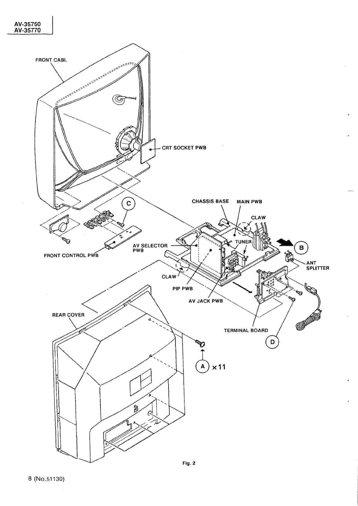
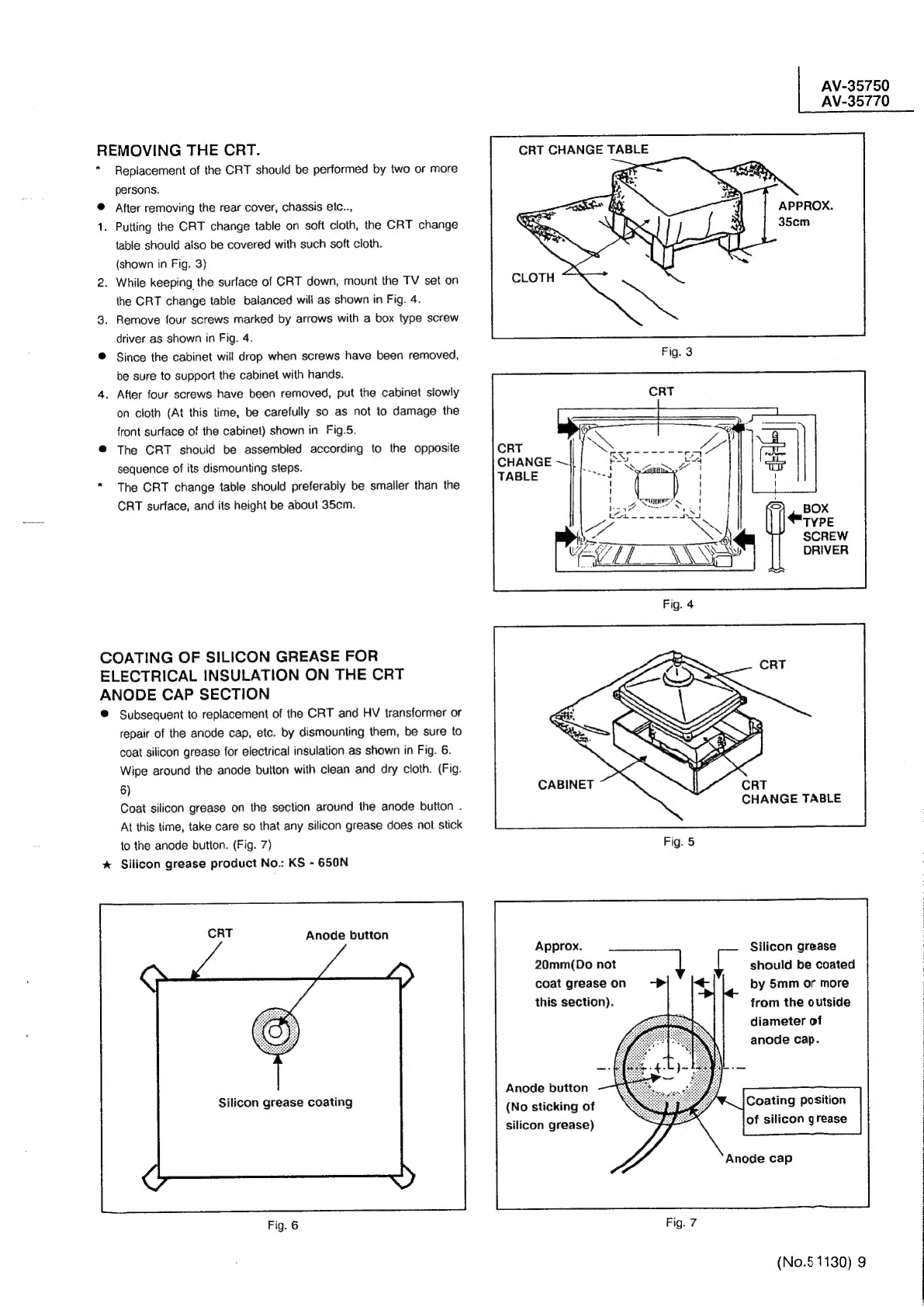
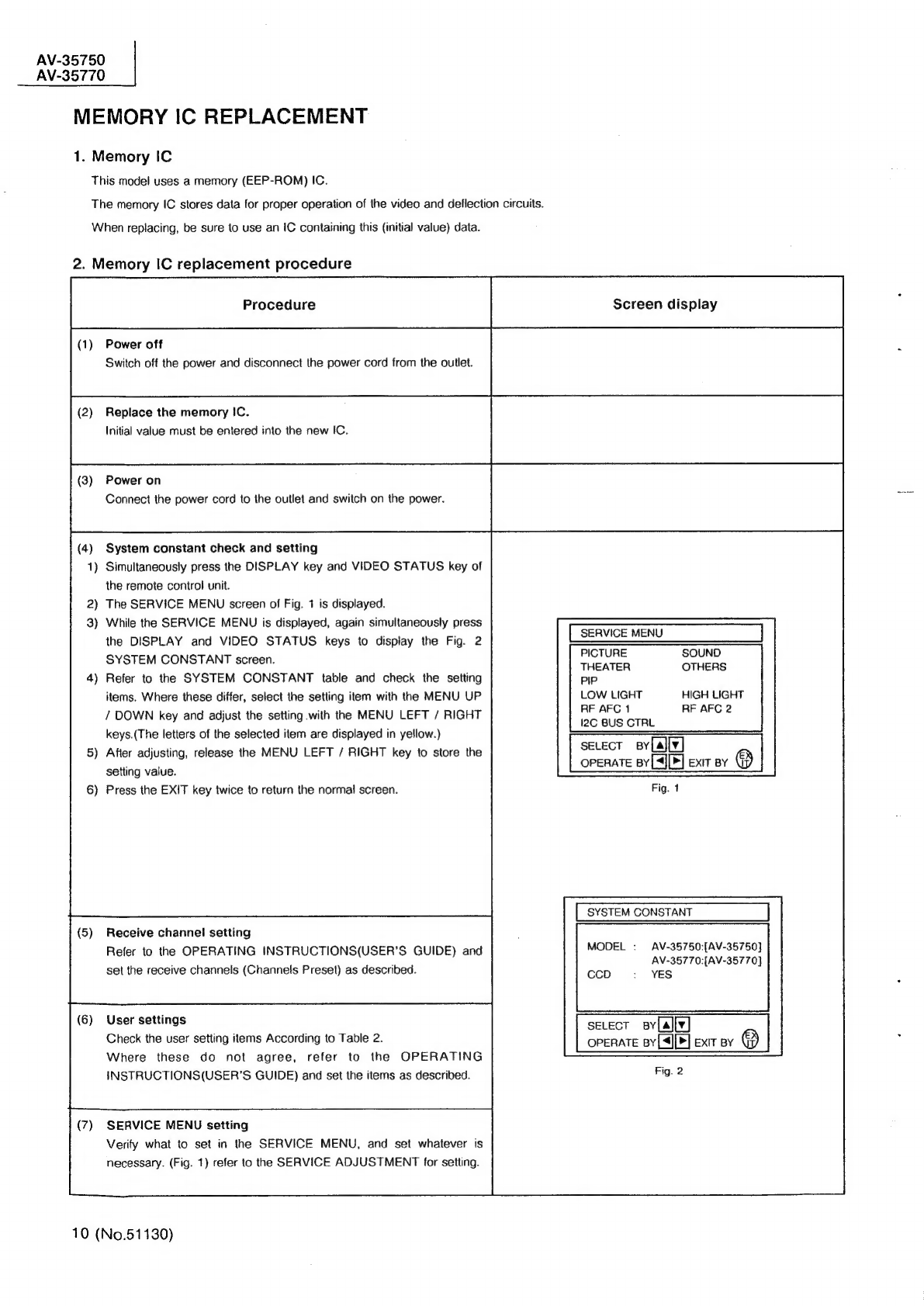
JVC AV-35750 User manual

AV-
3
5
7
5
Oissecs
aca
AV-3
5
7
7
Dus
2
ME
SAFETY
PRECAUTIONS
.........
0...
ccc
ne
eet
eee
ees
3
Ml
FEATURES:
665.5
640s
ae
a
tere
ites
Be
ire
be
Mins
Bt
eee
ee
a
eee
ahd
ane
ele
eer
lid
eee
aha
4
%*
OPERATING
INSTRUCTIONS
[AV-35750]
(APPENDED)
..............2----00--
1-1~1-16
%
OPERATING
INSTRUCTIONS
[AV-35770]
(APPENDED)
.............-----+--e-
{-1~
1-16
Mi
DIFFERENCE
LIST
OF
MAIN
PARTS...
2.26.2
ee
ee
te
es
5
MB
SPECIFIC
SERVICE
INSTRUCTIONS
....
1.6...
tee
es
6
M
SERVICE
ADJUSTMENTS...
1...
eee
es
12
%
STANDARD
CIRCUIT
DIAGRAM
(APPENDED)
..............0
00
cece
eee
eens
2-1~
2-28
MEPARTS
UIST
2
ecn35
Gh3e
Be
eee
eS
oe
es
ee
BA
en
a
GA
ta
eae
ee
toes
eet
27
a
SS
SS
SS
COPYRIGHT
©
1996
VICTOR
COMPANY
OF
JAPAN,LTD.
Noon
at
Jul.1996

AV-35750
AV-35770
SPECIFICATIONS
ptm
TP
omtent
Dimensions
(W
XH
xD)
Mass
TV
System
and
Color
system
TV
RF
System
Color
System
Sound
System
TV
Receiving
Channels
and
Frequency
VL
Band
VH
Band
UHF
Band
CATV
Receiving
Channels
and
Frequency
(Quartz
Synthesizer
system)
Low
Band
High
Band
Mid
Band
Super
Band
Hyper
Band
ULTRA
Band
Sub
Mid
Band
TV/CATV
Total
Channel
Intermediate
Frequency
Video
IF
Carrier
Sound
IF
Carrier
Color
Sub
Carrier
Antenna
terminal
Power
Input
Power
Consumption
Input
Current
Picture
Tube
High
Voltage
Speaker
Audio
Power
Output
Input
(1,
2)
S-VIDEO
IN
Variable
/
Fix
Audio
Output
AV
Compulink
Input
Remote
Control
Unit
33-7/8"
X
30-1/8"
x
23-3/4”
/
86cm
x
76.5cm
x
60.3em
152.3lbs
/
69.2kg
CCIR
(M)
NTSC
BTSC
(Multi
Channel
Sound)
(02
~
06)
54MHz
~
88MHz
(07
~
13)
174MHz
~
216MHz
(14
~
69)
470MHz
~
806MHz
(02
~
06,
A-8)
by
(02
~
06801)
(07
~
13)
by
(07
~
13)
(A
~
1)
by
(14
~
22)
(J
~
W)
by
(23
~
36)
(W
+1
~
W+
28)
by
(37
~
64)
(W
+29
~
W
+84)
by
(65
~
125)
(A8,
A4
~
A1)
by
(01,
96
~
99)
180
Channels
(54MH2~
804MHz)
45.75MHz
41.25MHz
(4.5MHz)
3.58MHz
75Q
(VHF/UHF)
Terminal,
F-Type
Connector
120V
AC,
60Hz
135W(US)
1,.8A(CA)
35”(89cm)
measured
diagonally,
Full
Square
31kV
+1.3kV
(at
zero
beam
current
)
3-3/16”
x
4-3/4”
/
8X
12cm
Oval
Type
x2
3W
+3W
Video
:
1
Vp-p
75Q
(RCA
pin
jack)
Audio
:
500
mV
rms
(-4dBs),
High
impedance
(RCA
pin
jack)
Y
:
1
Vp-p
positive
(negative
sync
provided,when
terminated
with
752)
C
:
0.286
Vp-p
(
burst
signal,
when
terminated
with
75Q)
Variable:
More
than
0~
1550mV
rms
(
+
6dBs)
Low
Impedance
(400Hz
when
modulated
100%)
(RCA
pin
jack)
Fix
:
500
mV
rms
(-4dBs)
Low
Impedance
(400Hz
when
modulated
100%)
(RCA
pin
jack)
RECEIVER
/
AMP:
3.5mm
mini
jack
VCR
ONLY
:
3.5mm
mini
jack
RM-G742-1C
(AA/RG/UM-3
dry
baltery
x
2)
:
[AV-35750(US&CA)]
RM-C732-1A
(AAA/ROS/UM-4
dry
battery
x2)
:
[AV-35770(US)]
Design
&
specification
subject
to
change
without
notice.
2
(No.51130)

SAFETY
PRECAUTIONS
The
design
of
this
product
contains
special
hardware,
many
circuits
and
components
specially
for
safety
purposes.
For
continued
pro-
tection,zno
changes
should
be
made
to
the
original
design
unless
authorized
in
writing
by
the
manufacturer.
Replacement
parts
must
be
identical
to
those
used
in
the
original
circuits.
Service
should
be
performed
by
qualified
personnel
only.
Alterations
of
the
design
or
circuitry
of
the
products
should
not
be
made.
Any
design
alterations
or
additions
will
void
the
manufactur-
er's
warranty
and
will
further
relieve
the
manufacturer
of
responsi-
bility
for
personal
injury
or
property
damage
resulting
therefrom.
Many
electrical
and
mechanical
parts
in
the
products
have
special
safety-related
characteristics.
These
characteristics
are
often
not
evident
from
visual
inspection
nor
can
the
protection
afforded
by
them
necessarily
be
obtained
by
using
replacement
components
rated
for
higher
voltage,
wattage,
etc.
Replacement
parts
which
have
these
special
safety
characteristics
are
identified
in
the
parts
list
of
Service
manual.
Electrical
components
having
such
fea-
tures
are
identified
by
shading
on
the
schematics
and
by
(A)
on
the
parts
list
in
Service
manual.
The
use
of
a
substi-
tute
replacement
which
does
not
have
the
same
safety
characteris-
tics
as
the
recommended
replacement
part
shown
in
the
parts
list
of
Service
manual
may
cause
shock,
fire,
or
other
hazards.
Use
isolation
transformer
when
hot
chassis.
The
chassis
and
any
sub-chassis
contrained
in
some
products
are
connected
to
one
side
of
the
AC
power
fine.
An
isolation
transform-
er
of
adequate
capacity
should
be
inserted
between
the
product
and
the
AC
power
supply
point
while
performing
any
service
on
some
products
when
the
HOT
chassis
is
exposed.
Don't
short
between
the
LIVE
side
ground
and
ISOLAT-
ED(NEUTRAL)
side
ground
or
EARTH
side
ground
when
re-
pairing.
Some
model's
power
circuit
is
partly
different
in
the
GND.
The
dif-
ference
of
the
GND
is
shown
by
the
LIVE
:
(
)
side
GND,
the
ISOLATED(NEUTRAL)
:
(
ar)
side
GND
and
EARTH
:
(
)
side
GND.
Don't
short
between
the
LIVE
side
GND
and
!SOLAT-
ED(NEUTRAL)
side
GND
or
EARTH
side
GND
and
never
measure
with
a
measuring
apparatus
(oscilloscope
etc.)
the
LIVE
side
GND
and
ISOLATED(NEUTRAL)
side
GND
or
EARTH
side
GND
at
the
same
time.
If
above
note
will
not
be
kept,
a
fuse
or
any
parts
will
be
broken.
if
any
repair
has
been
made
to
the
chassis,
it
is
recommended
that
the
B,
setting
should
be
checked
or
adjusted
(See
ADJUSTMENT
OF
B,
POWER
SUPPLY).
The
high
voltage
applied
to
the
picture
tube
must
conform
with
that
specified
in
Service
manual.
Excessive
high
voltage
can
cause
an
increase
in
X-Ray
emission,
arcing
and
possible
component
dam-
age,
therefore
operation
under
excessive
high
voltage
conditions
should
be
kept
to
a
minimum,
or
should
be
prevented.
If
severe
ar-
cing
occurs,
remove
the
AC
power
immediately
and
determine
the
cause
by
visual
inspection
(incorrect
installation,
cracked
or
melted
high
voltage
harness,
poor
soldering,
etc.).
To
maintain
the
proper
minimum
level
of
soft
X-Ray
emission,
components
in
the
high
volt-
age
circuitry
including
the
picture
tube
must
be
the
exact
replace-
ments
or
alternatives
approved
by
the
manufacturer
of
the
com-
plete
product.
Do
not
check
high
voltage
by
drawing
an
arc.
Use
a
high
voltage
meter
or
a
high
voltage
probe
with
a
VTVM.
Discharge
the
picture
tube
before
attempting
meter
connection,
by
connecting
a
clip
lead
to
the
ground
frame
and
connecting
the
other
end
of
the
lead
through
a
10kQ
2W
resistor
to
the
anode
button.
When
service
is
required,
observe
the
original
lead
dress.
Extra
pre-
caution
should
be
given
to
assure
correct
lead
dress
in
the
high
voltage
circuit
area.
Where
a
short
circuit
has
occurred,
those
com-
ponents
that
indicate
evidence
of
overheating
should
be
replaced.
Always
use
the
manufacturer's
replacement
components.
10°
(1)
(2)
tsolation
Check
(Safety
for
Electrical
Shock
Hazard)
After
re-assembling
the
product,
always
perform
an
isolation
check
on
the
exposed
metal
parts
of
the
cabinet
(antenna
terminals,
vid-
eo/audio
input
and
output
terminals,
Control
knobs,metal
cabinet,
screwheads,
earphone
jack,
control
shafts,
etc.)
to
be
sure
the
prod-
uct
is
safe
to
operate
without
danger
of
electrical
shock.
Dielectric
Strength
Test
The
isolation
between
the
AC
primary
circuit
and
all
metal
parts
ex-
posed
to
the
user,
particularly
any
exposed
metal
part
having
a
re-
turn
path
to
the
chassis
should
withstand
a
voltage
of
1100V
AC
(r.m.s.)
for
a
period
of
one
second.
(....
Withstand
a
voltage
of
1100V
AC
(r.m.s.)
to
an
appliance
rat-
ed
up
to
120V,
and
3000V
AC
(r.m.s.)
to
an
appliance
rated
200V
or
more,
for
a
period
of
one
second.)
This
method
of
test
requires
a
test
equipment
not
generally
found
in
the
service
trade.
Leakage
Current
Check
Plug
the
AC
line
cord
directly
into
the
AC
outlet
(do
not
use
a
line
isolation
transformer
during
this
check.).
Using
a
"Leakage
Current
Tester”,
measure
the
leakage
current
from
each
exposed
metal
part
of
the
cabinet,
particularly
any
exposed
metal
part
having
a
return
path
to
the
chassis,
to
a
known
good
earth
ground
(water
pipe,
etc.).
Any
leakage
current
must
not
exceed
0.5mA
AC
(r.m.s.).
¢
Alternate
Check
Method
Piug
the
AC
line
cord
directly
into
the
AC
outlet
(do
not
use
a
line
isolation
transformer
during
this
check.).
Use
an
AC
voltmeter
hav-
ing
1000
ohms
per
volt
or
more
sensitivity
in
the
following
manner.
Connect
a
1500Q
10W
resistor
paralleled
by
a
0.15pF
AC-type
ca-
pacitor
between
an
exposed
metal
part
and
a
known
good
earth
ground
(water
pipe,
etc.).
Measure
the
AC
voltage
across
the
resis-
tor
with
the
AC
voltmeter.
Move
the
resistor
connection
to
each
ex-
posed
metal
part,
particularly
any
exposed
metal
part
having
a
re-
turn
path
to
the
chassis,
and
measure
the
AC
voltage
across
the
re-
sistor.
Now,
reverse
the
plug
in
the
AC
outlet
and
repeat
each
mea-
surement.
Any
voltage
measured
must
not
exceed
0.35V
AC
{r.m.s.).
This
corresponds
to
0.56mA
AC
(r.m.s.).
AC
VOLTMETER
(HAVING
1000Q/V,
OR
MORE
SENSITIVITY)
0.15pF
AC-TYPE
PLACE
THIS
PROBE
ON
EACH
EXPOSED
METAL
PART
15002
10W
GOOD
EARTH
GROUND
High
voltage
hold
down
circuit
check.
After
repair
of
the
high
voltage
hold
down
circuit,
this
circuit
shall
be
checked
to
operate
correctly.
See
item
"How
to
check
the
high
voltage
hold
down
circuit”.
This
mark
shows
a
fast
operating
fuse,
the
letters
indicated
below
show
the
rating.
(No.51
130)
3
AV-35750
AV-35770

AV-35750
AV-35770
FEATURES
®
New
chassis
design
enables
use
of
a
main
board
with
simplified
circuitry.
®
Comb
filter
improved
picture
quality.
®
Provided
with
miniature
tuner
(TV
/
CATV)
®
Full-square
CRT
(cathode
ray
tube)
reproduces
fine
textured
picture
in
every
detail.
®@
PLL
synthesizer
system
TV
/
CATV
totaling
180
channels.
@®
AV
COMPU
LINK
terminals
allow
simultaneous
mode
switching
of
the
TV,
connected
receiver
(or
amplifier)
and/or
VCR.
4
(No.51130)
Closed-caption
broadcasts
can
be
viewed.
With
AUDIO.
VIDEO
INPUT
terminal.
S-VIDEO
input
terminal
for
taking
best
advantage
of
Super
VHS.
Variable
audio
output
terminal.
Built-in
PIP
system.
An
auto
demonstration
function
demonstrates
the
features
of
this
model.
\2C
bus
control
utilizes
single
chip
ICs.

DIFFERENCE
LIST
OF
MAIN
PARTS
rea
|
ero
AV-35750(US)
AV-35750(CA)
AV-35770(US)
Part
name
inne
|
serene
[YC
earsoowrovensey
|
sorsovnae
[=
(|
emma
remwse
|somenne
[|
terme
pfeenmeswes
[amen
[|
ve
a
sreoorecuny
|
cowaeara
[=|
commen
rfnsrsocencn
[=|
eo
[
resicw
|
eran“
Ea
[>
>
elel
| |
|
ele]
(No.84130)
5
This manual suits for next models
4
Table of contents
Other JVC TV manuals

JVC
JVC 0405TKH-CR-MU User manual

JVC
JVC AV-14F16 User manual

JVC
JVC AV-36F703/Y User manual

JVC
JVC AV-27D502/R User manual

JVC
JVC AV-28GT20U User manual

JVC
JVC LT-47DV8BJ User manual

JVC
JVC I Art AV-20FA44/SA User manual

JVC
JVC AV32L2EUGR User manual

JVC
JVC AV-20NX14, AV-21DX14 User manual

JVC
JVC AV-21L91-BK User manual