JVC AV-29BD3 EK
General Information
Also Covers
JVC AV-29BD3 EN
JE Chassis
SAFE Y PRECAU IONS - See Matrix
FEA URES - See Matrix
MAIN DIFFERENCE PAR S LIS - See book-
marks section
SPECIFIC SERVICE INS RUC IONS
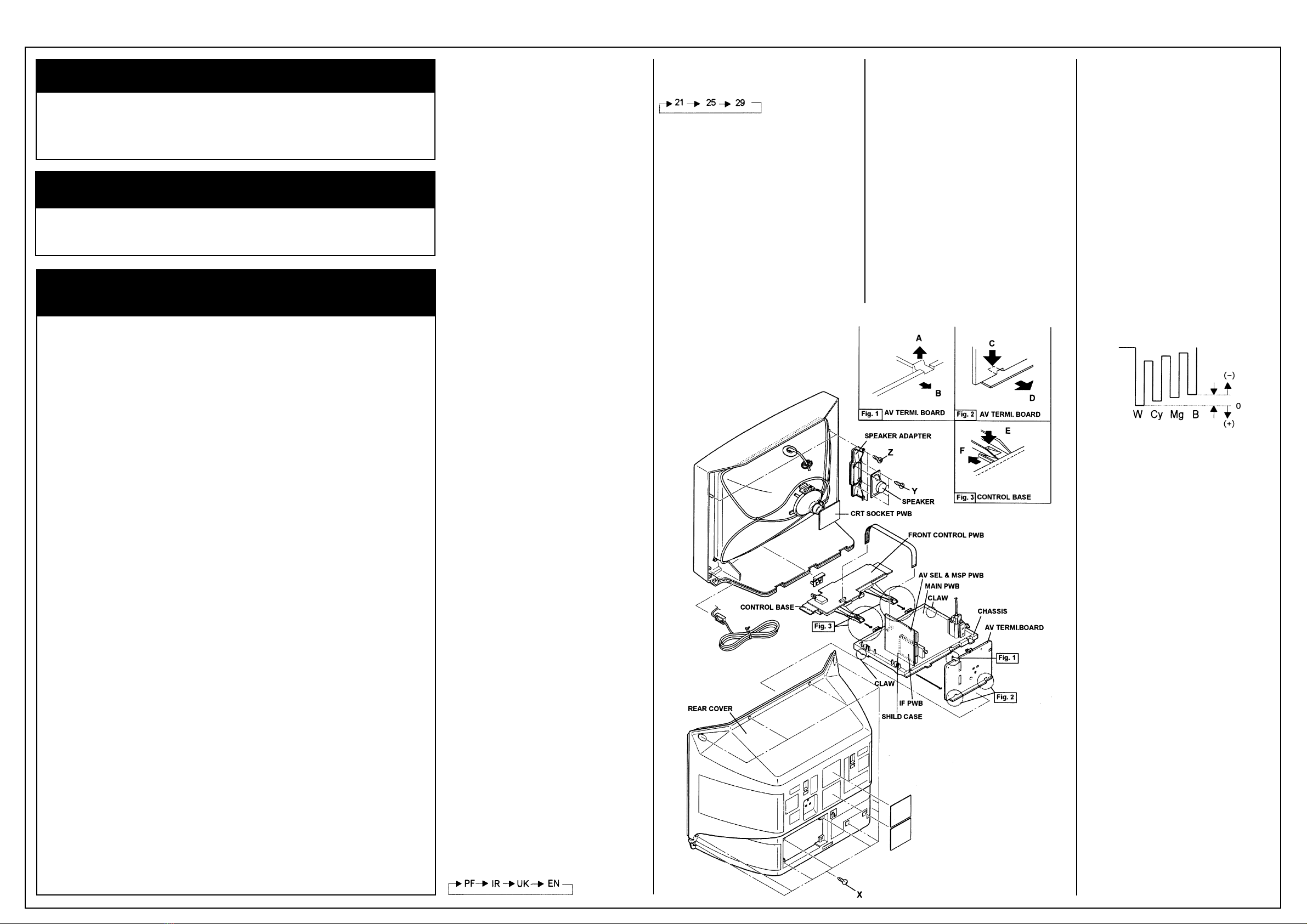
DISASSEMBLY PROCEDURE
REMOVING HE REAR COVER
1. Unplug the power cord
2. Remove the 12 screws marked “X” as shown
in the figure.
. Withdraw the rear cover toward you.
REMOVING HE CHASSIS
• After removing the rear cover.
1. Slightly raise the both sides of the chassis by
hand and remove the two claws under the both
sides of the chassis from the front cabinet.
2. Withdraw the chassis backward. (If necessary,
take off the wire clamp, connectors etc.)
REMOVING HE AV ERMI. BOARD
• After removing the rear cover.
1. While raising the claw marked “A” remove the
top of the AV TERMI. Board slightly in the
direction of arrow “B” as shown in Fig. 1.
2. Remove the claws marked “C” under the AV
TERMI. Board remove the AV TERMI. Board in
the arrow direction marked “D” as shown in Fig. 2
REMOVING HE CON ROL BASE
1. While pushing down the claws marked “E”,
remove the CONTROL BASE in the arrow
direction “F” as shown in Fig. . (If necessary,
take off the wire clamp, connectors etc.)
REMOVING HE SPEAKER ADAP ER
• After removing the rear cover.
1. Remove the two screws marked “Z” as shown
in figure.
2. Follow the same steps when removing the
other hand speaker adapter.
REMOVING HE SPEAKER
• After removing the rear cover.
1. Remove the 4 screws marked “Y” as shown in
figure.
2. Follow the same steps when removing the
other hand speaker.
CHECKING HE PW BOARD
1. To check the back side of the PW Board.
1) Pull out the chassis. (Refer to REMOVING THE
CHASSIS).
2) Erect the chassis vertically so that you can
easily check the back side of the PW Board.
[CAUTION]
• When erecting the chassis, be careful so that
there will be no contacting with other PW
Board.
• Before turning on power, make sure that the
wire connector is properly connected.
WIRE CLAMPING AND CABLE IES
1. Be sure to clamp the wire.
2. Never remove the cable tie used for tying the
wires together. Should it be inadvertently
removed, be sure to tie the wires with a new
cable tie
REPLACEMEN OF MEMORY ICs - See Matrix
SE ING VALUES OF SYS EM CONS AN
SE
Setting item
1. COUNTRY
Setting content
Setting item
2. INCH
Setting content
Setting value
AV-29BD EN: EN (29")
AV-2SBD EK: UK (29")
USER SE ING VALUES - See Matrix
SERVICE MENU SE ING I EMS - See Matrix
BEFORE S AR ING SERVICE ADJUS MEN S
- See Matrix
BASIC OPERA ION OF SERVICE MENU - See
Matrix
For B1 POWER SUPPLY CHECK, FOCUS, IF
CIRCUI , and VSM PRESE ADJUS MEN S -
See Matrix
VIDEO/CHROMA CIRCUI ADJUS MEN - See
Matrix
For Adjustments of WHI E BALANCE, SUB
BRIGH , SUB CON ., SUB COLOUR I, SUB
IN , BLACK OFFSE (SECAM) - See Matrix.
Item
Adjustment of SUB COLOUR II
Measuring instrument
Signal Generator
Oscilloscope
Remote Control Unit
est point
TP-47B
TP-E
[CRT SOCKET PWB]
Adjustment part
5.COLOUR (PAL~NTSC)
Description
[Method of adjustment using measuring instru-
ment]
Adjustment part
PAL COLOUR
Description
(PAL COLOUR)
Recommended Safety Parts
Item Part No. Description
Matrix
Item See Model Vol
Safety Precautions ............................................................. JVC AV-28WFR1 EKS 8
Features ...................................................................................JVC AV-25BD EK 8
Other Adjustments.................................................................... JVC AV-29TS2 EK 6
AV-29BD3EN
1 LC10079-001B-U REAR COVER
LC1009 -001B-U CHASSIS BASE
5 LCT01 -001A-U INST. BOOK For ENG/GER/FRA/NED/ITA/ESP
6 LCT01 4-001A-U INST. BOOK For FIN/NOR/DEN/SWE/POR
10 AEEMP001-185 POWER CORD
11 CM46618-A01-E POWER CORD CLAMP
12 LC20076-001A-U RATING LABEL For ENG/GER/ITA
1 LC20077-002A-U RATING LABEL For ENG/ESP
C1521 QFZ0152-4001 MPP CAP. 4000pF 1.5kVH±2.5%
C1522 QFZ0152-9501 MPP CAP. 9500pF 1.5kVH±2.5%
C152 QFP 2GJ-22 PP CAP. 0.022µF 400V J
C1525 QFZ0119-684 MPP CAP. 0.68µF 200V±%
C15 1 QFZ0119-154 MPP CAP. 0.15µF 200V±%
C1902 QCZ9086-472 C CAP. 4700pFAC400V P
C190 QCZ9086-472 C CAP. 4700pFAC400V P
C1904 QCZ9086-472 C CAP. 4700pFAC400V P
C1992 QCZ9079-471 C CAP. 470pFAC250V K
C199 QCZ9079- 2 C CAP. 00pFAC250V K
C8901 QFZ9040-474N MF CAP. 0.47µF AC275V M
C8904 QFZ9040-47 N MF CAP. 0.047µF AC275V M
CP1952 ICP-N50-Y I.C.PROTECT
CP195 ICP-N50-Y I.C.PROTECT
D1901 D SBA60 DIODE BRIDGE
F8901 QMF51D2- R15J1 FUSE . 15A
FR1551 QRZ9017-4R7 4.7Ω1/4W J
FR1552 QRZ9021-1R0 1.0Ω1W J
FR155 QRZ9021-1R0 1.0Ω1W J
FR1954 QRZ9022-R82 0.82Ω1W K
IC1902 TLP721F(D4-GR) IC. (PH.COUPLER)
L01 CELD020-004J7 DEGAUSSING COIL
LF8901 CE42144-001J2 LINE FILTER
Q1521 BU2508AX POWER TRANSISTOR H OUT
R040 QRZ9017-470 F R 47Ω1/4W J
R1466 QRJ146J-2R2X C R 2.2Ω1/4W J
R1585 QRA14CF-2941Y MF R 2. 94kΩ1/4W F
R1586 QRA14CF-1582Y MF R 15.8kΩ1/4W F
R1991 QRZ0057-825 C R 8.2MΩ1W J
S8901 QSP4K21-C01 PUSH SWITCH MAIN POWER
SK 001 CE425 5-001J1 C.R.T.SOCKET
T1551 CETH019-00AJ1 H.V. TRANSF. (SERVICE)
T1901 CETS08 -001J7 SWITCH. TRANSF.
TH8901 CEKP010-001J2 W. P. THERMISTOR
V01 A68ESF002X011 ITC PICTURE TUBE(Inc. DY. PC, WED)
AV-29BD3EK Only
5 LCT01 1-001A-U INST. BOOK
10 AEEMP001-185A POWER CORD
12 LC20075-002A-U RATING LABEL
1. Receive a PAL full field colour bar signal
(75% white).
2. Select 2.V/C from the SERVICE MENU.
. Select 7.COLOUR with the FUNCTION UP/
DOWN key.
4. Set the initial setting value for PAL COLOUR
with the FUNCTION - or + key.
5. Connect the oscilloscope between TP-47B
and TP-E
6. Adjust PAL COLOUR and bring the value of
(A) in the illustration to 0V (voltage differ-
ence between white and blue).
7. Press the MENU key and memorize the
setting value.
Adjustment part
SECAM COLOUR (AV-29BD EN)
Description
(SECAM COLOUR)
1. Receive a SECAM full field colour bar signal
(75% white).
2. Set the initial setting value of SECAM
COLOUR with the FUNCTION
-/+
key.
. Adjust SECAM COLOUR and bring the
value of (A) of the illustration to +5V (W~B).
4. Press the MENU key and memorize the
setting value.
Adjustment part
NTSC .58 COLOUR
Description
(NTSC .58 COLOUR)
1. Input a NTSC .58MHz COMPOSITE
VIDEO signal (full field colour bar with 75%
white) from the EXT terminal.
2. Set the initial setting value of NTSC .58
COLOUR with the FUNCTION
-/+
key.
. Adjust NTSC .58 COLOUR and bring the
value of (A) of the illustration to 0V (W~B).
4. Press the MENU key and memorize the
setting value.
(NTSC 4.4 COLOUR)
1. When NTSC 58 is set, NTSC 4.4 will be
automatically set at the respective values.
The End


