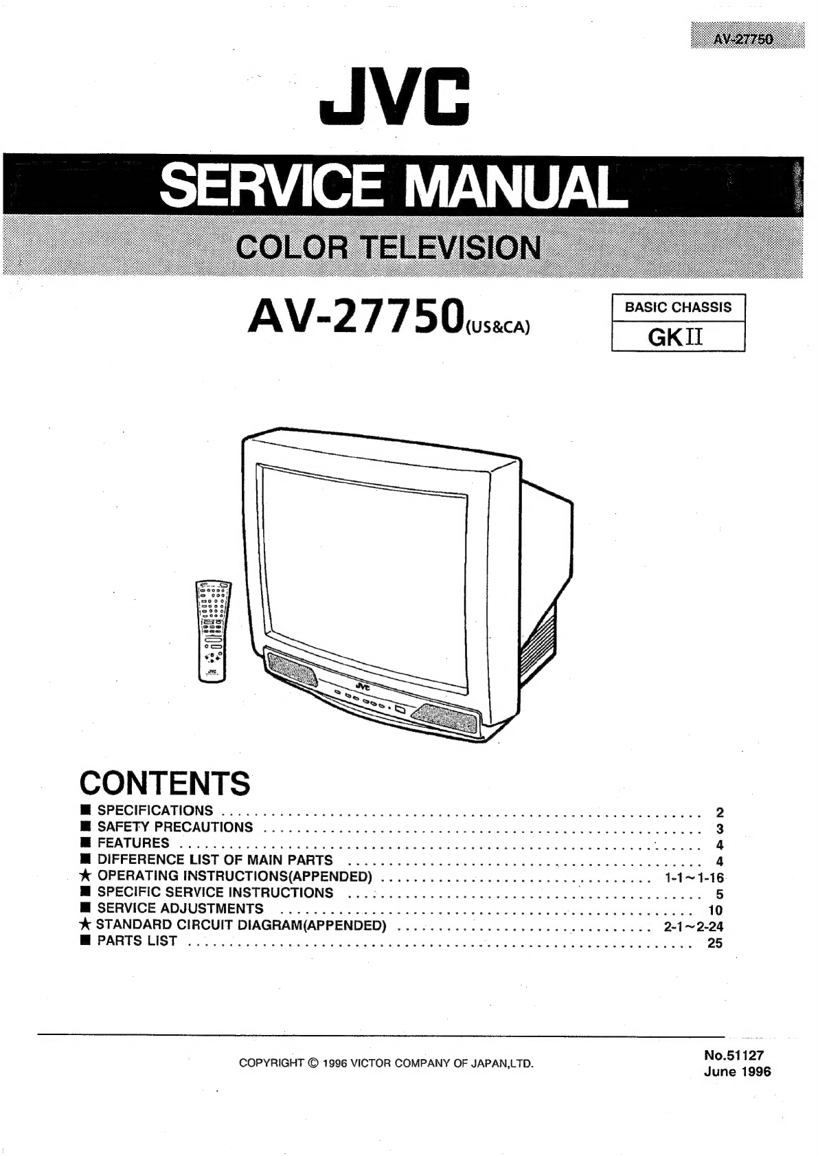
SERVICE
MANUAL
AV-2
77
o)
0
ener
CONTENTS
M
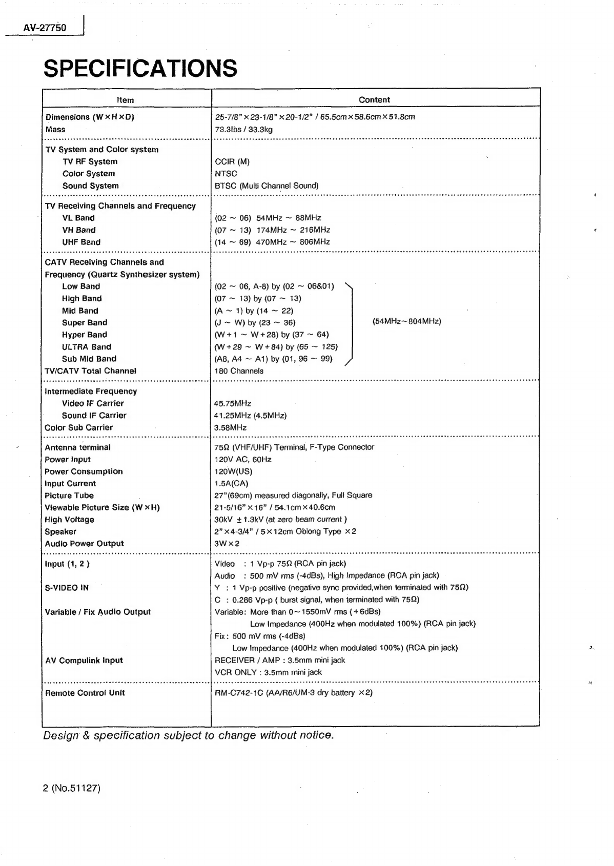
SPECIFICATIONS
.......0.0.0.0
0000s
ccc
cece
cece
cece
eee
eecceceeeunsceeucuaecnnas
2
M
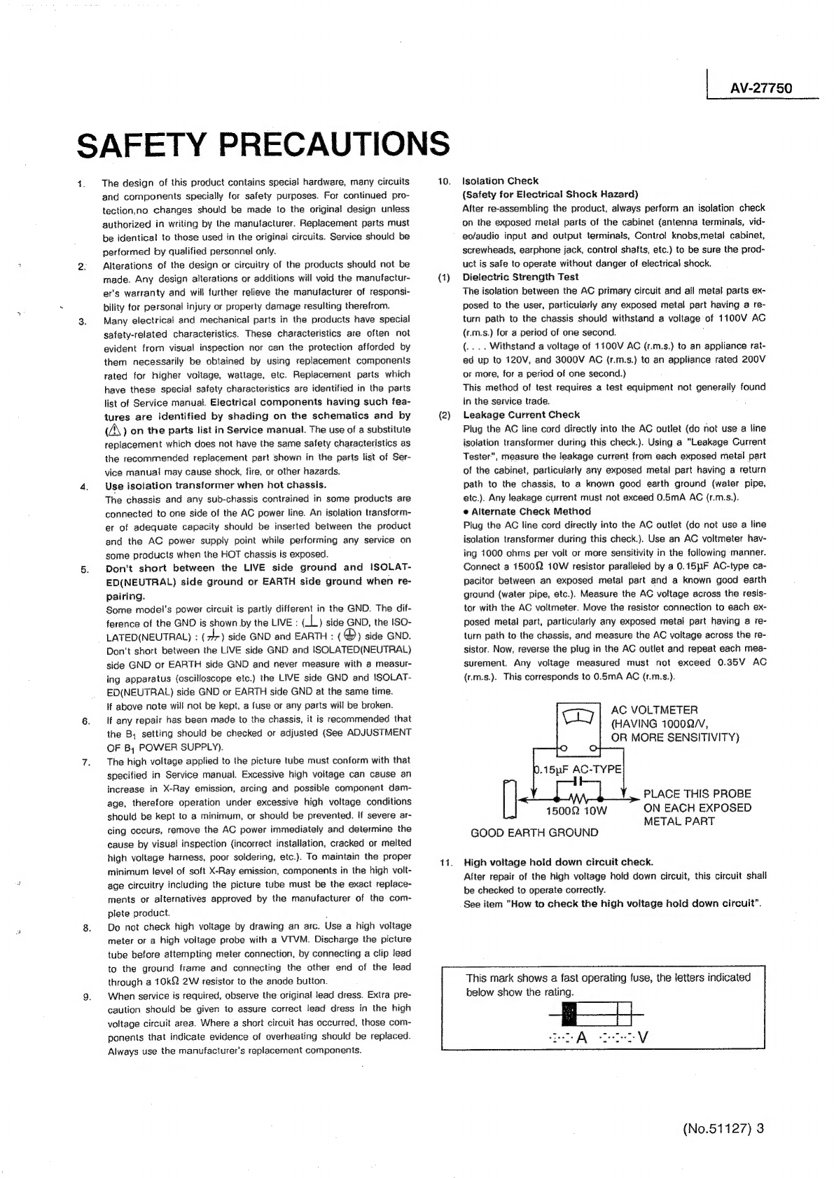
SAFETY
PRECAUTIONS
.............000
000.
cece
cece
cece
eee
eeeeeentaeeennes
3
ME
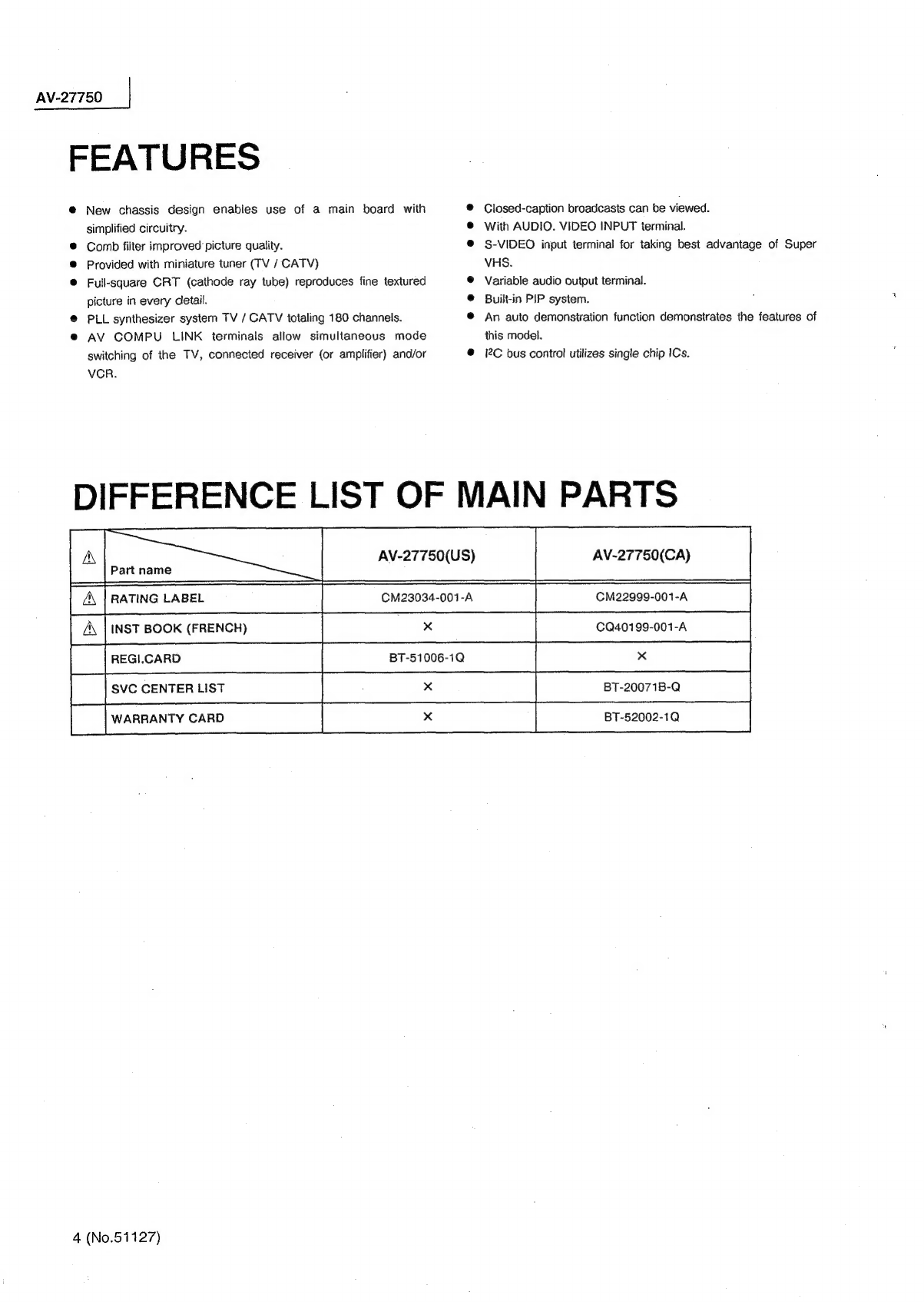
FEATURES?
3
c.04
cre
ee
2
Ghee
hah
acy
abe
cia
Wiig
athe
th
ate
oat
ben
nnn
Oa
Loe
sed
4
M
DIFFERENCE
LIST
OF
MAINPARTS
...............--0--eeeeee
ot
eee
eee
4
%
OPERATING
INSTRUCTIONS(APPENDED)
...........0...
cc
cceeeeeeeeeeeaee
1-1~1-16:
M
SPECIFIC
SERVICE
INSTRUCTIONS
...:.........0..0.ceeeeeeeee
Dhaai
aged
ates
5
M
SERVICE
ADJUSTMENTS
....
00...
0c
cece
cence
eeeeeveeennees
10
%&
STANDARD
CIRCUIT
DIAGRAM(APPENDED)
................-----
S
sbaeatn
sas
2-1~2-24
BM
PARTS
(IS
cre
aid
nh
oe
Hs
naeeaet
car
iuteiatok:
SR
aCe
e
ie
at
ane
tae
25
No.51127
COPYRIGHT
©
1996
VICTOR
COMPANY
OF
JAPAN,LTD.
June
1996