ENGLISH
The
Following
Functions
Can
Be
Performea
...............::ccscccssccsssrsesssecceteseeseeensscanees
3
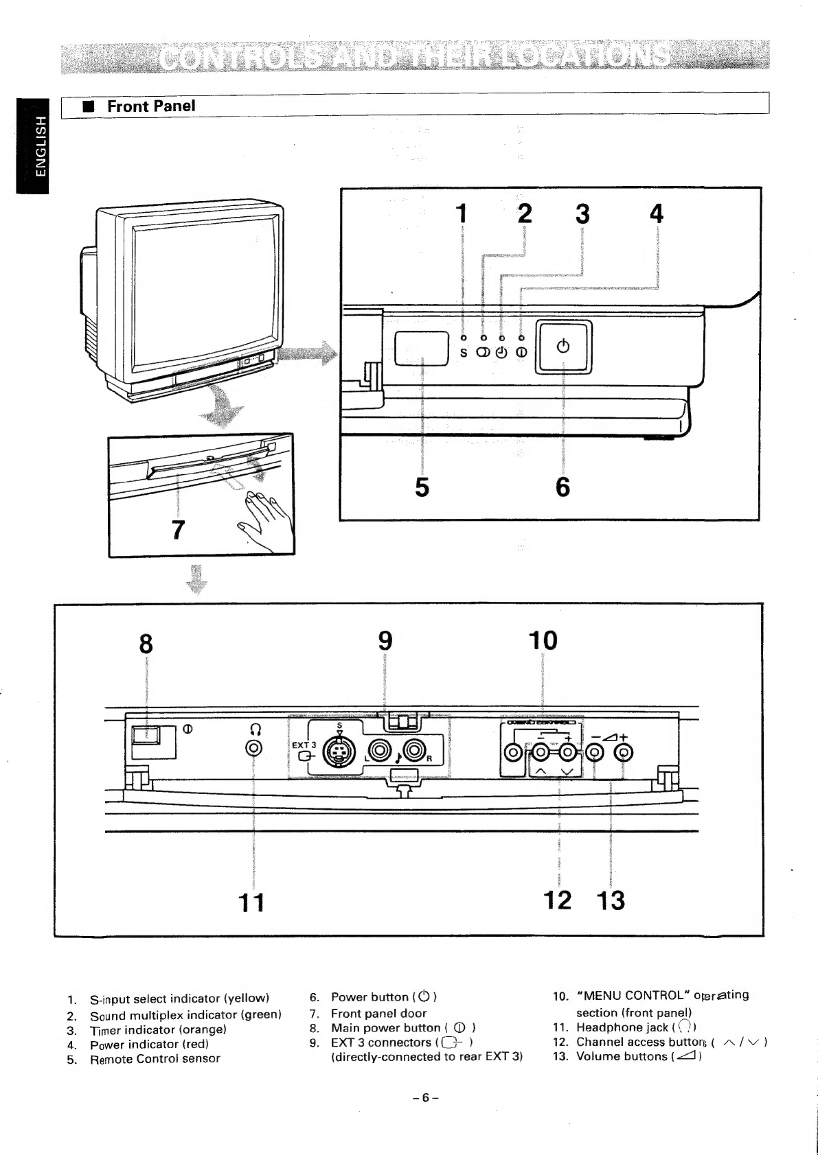
Controls
and
Their
Locations.
.................ccccccccccccesseesceeececceceececceuseccessssesueseeseerseenseneces
6
BE
Front
Panels...
cccccces
Ssccasedevascevsovees
de
cxsadsocuincsecdeves
evens,
saseset
Sasvsvaucueseavenncccasteyesdesse
6
ME
REMOTE
GONTION
ie.
ciisscecbetecavesecvaatecs
chess
seatoued
cavseaaaaasedancéeasestsassoacdagsseeteedgntedacevectel
7
BB
Rear.
Pare
i
cccccccc2.
25
5c
edhe
ce
ccevaidsaiad
ah
sacesdasvansebasdbisavvs
sasvisiiesteveve
eevssdalaieeveceuieee
8
Berial
COmmecti
anes.
cc
cicsc
eicdecvessesciede
aciee
ee
tesost
kan
isev
eo
peoeade
tea
ostaadeeerd
ov
esceattiessiae:
9
Remote
Control
Unit's
Preparation
and
Use
...................cccccccccesssscsceeseeessseseesuesesseoss
9
@
Preparation
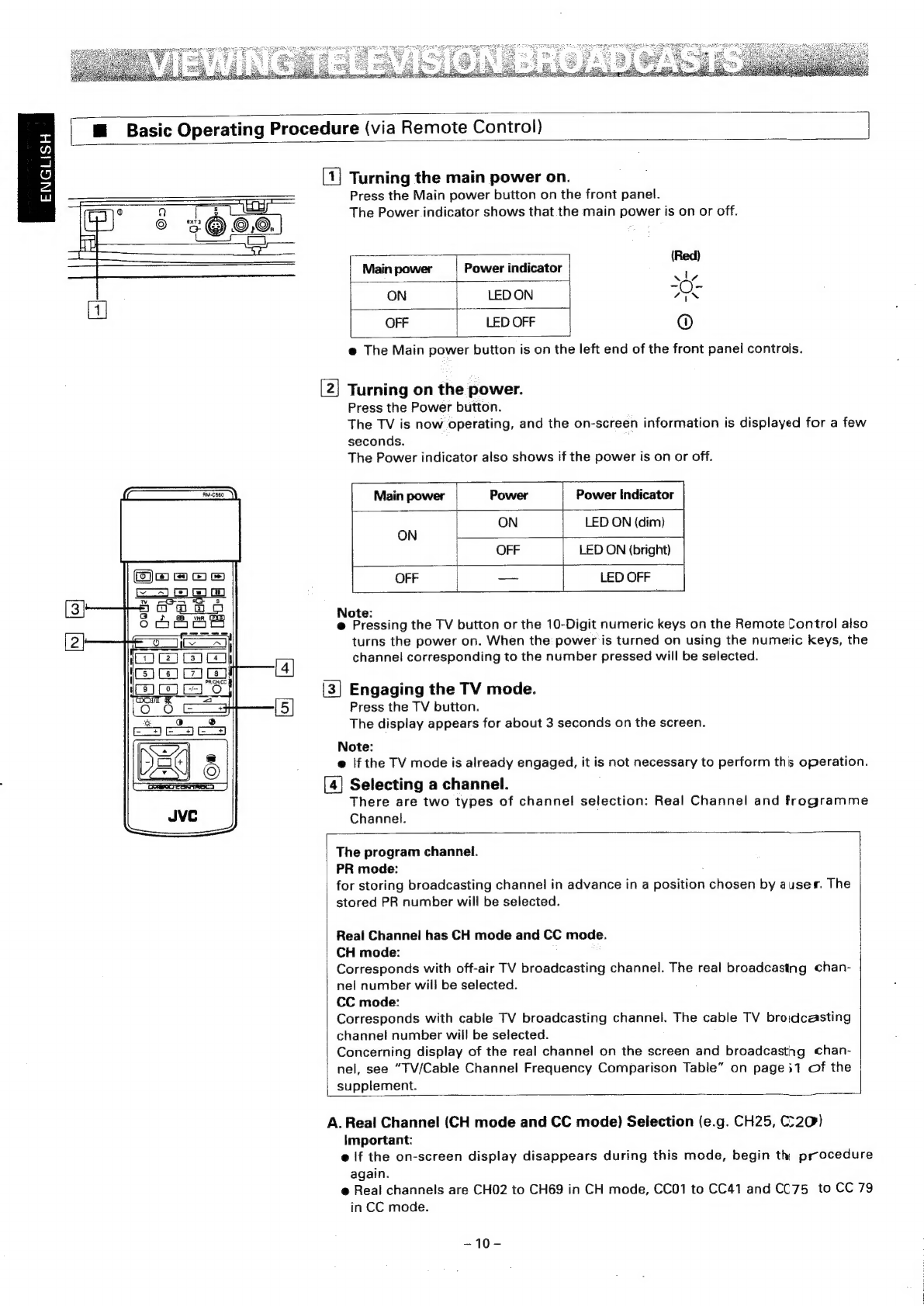
Viewing
Television
Broadcasts
...............ccccccccsscsessecesseeevsceeesscecssaesaeseaetsesstensceceanees
M@
Basic
Operating
Procedure
(via
Remote
Control)
M
Changing
the
Reception
System
(PAL/SECAM).............ccccccccecsesseseeseenes
@
Sound
multiplex
broadcast
reception
(stereo/dual
sound)
Switching
the
Input
Mode
(TV,
EXT
1,
EXT
2
and
EXT
3)
(Viewing
Pictures
From
a
Connected
Component)
Viewing
TV
Broadcasts
via
Front-Panel
Controls
Switching
Input
Mode
via
Front-Panel
Controls..................:.ccccccscccscscsesecssceseseeees
15
Picture/SOuNnd
Operations
0.0.0...
cceccssssceccesecsseceeeceecencevsuccsseeeeeccssucseseuesauareeereees
Picture/Sound
Level
Adjustment...........cc:cccssesseeeecee
SOUN
MUNG...
ceeeseccseeseeneeeeeseeeeeseeeesees
Listening
To
Surround
Effect
Sound
Listening
To
Sound
via
Built-in
Speakers
or
External
Speakers
Selecting
Sound
Tone
You
Prefer
............:ccccsesceccseesscssesssseccscesessnesvenee
Reducing
Picture
Switching
the
Aspect
Ratio
(4:3
-
16:9)
Operating
Menu
Functions
.....00.0.0.....
cece
To
Call
Up
a
Menu
Display
............:::00
Set-up
Station
ID.
ion
Auto
Shut
Off...
ecesscsctesesecsneeeeesseee
TONG
Preset
iy...
ceecikevsecteiseeseraeaeven
eres
Video
Status
MeMOry
ou...
cece
eereeeeeeees
Channel
Guard......ccccccsssescessscreeeeseceesees
Set-UP
MENU
.......ccceeccesseceneseesneeeeteneeeenenees
(1)
PROGRAM...........00066
2)
AFC
ON/OFF............006
3)
ON
SCREEN
ON/OFF...........
@<MESSAGE'ST
VE
ic
cccisicees
tes
cag
occa
vanencaaalaceasacdescpontevasieaveians
highend
decsatasoee'se
de
SOR
ClO
CK
rsa
saccsusahgeeatces
Sesaecs
Aiecvaa
Sia
cuavane
shcediacedene
soeeassavav)
spaaeehanad
gaat
dehvavassees
Savas
.
Reserve
Timer
FIOMIO
SUC
ra
asigs
ocd
ccenca
dk
ceceszcdiceeteewadicaseuli
ct
ahaa
oil
vdaetens
deans
dusieus
cuatdved
Quchesawendhaces
AAPWN>F
oom