TABLE OF CONTENTS
Section Title Page Section Title Page
Important Safety Precautions
INSTRUCTIONS
1. DISASSEMBLY
1.1 Manually removing the cassette tape ..........................1-1
1.2 Removing the major parts ............................................1-2
1.2.1 How to read the procedure table.............................1-2
1.2.2 Disassembly/assembly method ..............................1-2
1.3 Emergency display function .........................................1-4
1.3.1 Displaying the EMG information .............................1-4
1.3.2 Clearing the EMG history ........................................1-4
1.3.3
Details of the OSD display in the EMG display mode ...
1-5
1.3.4 EMG content description.........................................1-6
1.3.5 EMG detail information<1> .....................................1-7
1.3.6 EMG detail information<2> .....................................1-8
1.3.7 EMG detail information<3> .....................................1-8
1.4 Service position............................................................1-9
1.4.1 How to set the “Service position” ............................1-9
1.5 Jig RCU mode..............................................................1-9
1.5.1 Setting the Jig RCU mode ......................................1-9
1.5.2 Setting the User RCU mode ...................................1-9
1.6 Mechanism service mode ............................................1-9
1.6.1 How to set the “Mechanism service mode” .............1-9
1.6.2 How to exit from the “Mechanism service mode” ....1-9
1.7 Maintenance and inspection ......................................1-10
1.7.1 Cleaning ................................................................1-10
1.7.2 Lubrication ............................................................1-10
1.7.3
Suggested servicing schedule for main components ...
1-10
2. DISASSEMBLING/ASSEMBLING OF MECHANISM
1. Before disassembling/assembling .................................2-1
1.1 Notes...........................................................................2-1
1.2 Mechanism operation check .......................................2-1
1.3 Setting the mechanism assembling mode ..................2-1
1.4 Layout of the main mechanism parts ..........................2-2
1.5 Disassembling procedure table...................................2-3
2. Replacement of the main mechanism parts...................2-4
2.1 Cassette holder ...........................................................2-4
2.2 A/C head .....................................................................2-5
2.3 Guide arm, pinch roller arm ........................................2-6
2.4 Idler arm, idler gear 1/2 ...............................................2-6
2.5 Main brake(T), brake lever, tension arm,
reel disk(S/T), Rec safety lever ...................................2-6
2.6 Press lever, control cam, capstan brake assembly,
loading motor assembly ..............................................2-7
2.7 Capstan motor, load gear, control plate ......................2-8
2.8 Clutch unit assembly, direct gear ................................2-9
3. Mechanism timing chart ...............................................2-10
3. ADJUSTMENT
3.1 Precaution ....................................................................3-1
3.1.1 Required test equipments .......................................3-1
3.1.2 Required adjustment tools ......................................3-1
3.1.3 Color(colour) bar signal, color(colour) bar pattern ..3-1
3.1.4 Switch settings ........................................................3-1
3.1.5
Manual tracking mode (Auto tracking ON/OFF) setting ...
3-1
3.2 Mechanism compatibility adjustment ...........................3-2
3.2.1 Tension pole position...............................................3-2
3.2.2 FM waveform linearity .............................................3-2
3.2.3 Height and tilt of the A/C head ................................3-3
3.2.4 A/C head phase(X-value) ........................................3-3
3.3 Electrical Adjustment....................................................3-4
3.3.1 Servo circuit ............................................................3-4
3.3.1.1 Switching point ...................................................3-4
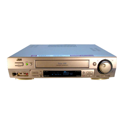
The following table lists the differing points between models HR-J691U, J691U(C), J694U, J695U(C) and J698U(C).
MODEL HR-J691U
ITEM
BODY COLOR BLACK PURE-SILVER BLACK
RCU ILUMINATION FUNCTION NOT USED USED
CHILD LOCK NOT USED USED NOT USED
4. CHARTS AND DIAGRAMS
4.1 BOARD INTERCONNECTIONS ................................4-3
4.2 MAIN(VIDEO/N.AUDIO) SCHEMATIC DIAGRAM.....4-5
4.3 MAIN(SYSCON) SCHEMATIC DIAGRAM.................4-7
4.4 MAIN(SW.REG) SCHEMATIC DIAGRAM..................4-9
4.5 MAIN(TUNER) SCHEMATIC DIAGRAM.................. 4-11
4.6 MAIN(FMA/DEMOD) SCHEMATIC DIAGRAM ........4-13
4.7 MAIN(FRONT) SCHEMATIC DIAGRAM..................4-15
4.8 MAIN(TERMINAL) SCHEMATIC DIAGRAM............4-17
4.9 MAIN CIRCUIT BOARD...........................................4-19
4.10 REMOTE CONTROLLER SCEMATIC DIAGRAM .4-21
4.11
FDP GRID ASSIGNMENTANDANODE CONNECTION .
4-21
4.12 WAVEFORMS ........................................................4-22
4.13 VOLTAGE CHARTS ...............................................4-23
4.14 CPU PIN FUNCTION .............................................4-24
4.15 SYSTEM CONTROL BLOCK DIAGRAM...............4-25
4.16 VIDEO BLOCK DIAGRAM .....................................4-27
4.17 AUDIO BLOCK DIAGRAM .....................................4-29
5. PARTS LIST
5.1 PACKING AND ACCESSORYASSEMBLY<M1> ........5-1
5.2 FINAL ASSEMBLY<M2> ..............................................5-2
5.3 MECHANISM ASSEMBLY<M4> ..................................5-4
5.4 ELECTRICAL PARTS LIST..........................................5-6
MAIN BOARD ASSEMBLY<03> ......................................5-6
A/C HEAD BOARD ASSEMBLY<12> ............................5-10
LOADING MOTOR BOARDASSEMBLY<55>...............5-10
HR-J691U(C) HR-J694U HR-J695U(C) HR-698U(C)
Notes: Mark is same as left.
