JYE DSO 082 User manual

DN082-02v02
JYE Tech - 1 - www.jyetech.com
LCD Digital Storage Oscilloscope
Manual of Operation
Applicable Models: 08201/08201B, 08202/08202B
1. Packing List
Items08201/08201B08202/08202B
082 Digital Storage Oscilloscope11
AC/DC Power Adapter 11
BNC Probe 1
Operating Manual 11
2. Precautions
1) Do not use asupply voltage higherthan thespecified maximuminput voltage of
9-12VDC to the instrument, as this may damage it and also invalidate your
warranty.
2) Donot attempt to directly measuremains powersupply without using astepdown
transformer.DO NOT EXCEED 50VMAX
3. Panel Description
The photo above showsthe screen and various frontpanel controls. Theyare explained
respectivelybelow.
Screen
1) Vertical position indicator thesmall triangle on the leftborder ofthe grid indicates the 0 voltinput
level. Its position can be changed up or down, bypressing [VPOS]and turning the adjustment knob.
2) Triggerlevel indicator the small triangle on the right border ofthe grid showsthe threshold
voltage oftrigger.It is triggeredwhen the input signal level crosses the threshold voltage level; the
trigger level is referenced to the input signal ground.
3) Windowposition indicator indicates the displayed portion ofsampled memory.The distance
between the twoshortvertical bars at the bottomrepresents thewhole length ofsampled memory,
which is usuallymuch longer thanthe screen can display.So at anygiven moment the screen can only
displayaportion ofthesampled data. The windowposition indicator showswhich portion is being
Fig 1

DN082-02v02
JYE Tech - 2 - www.jyetech.com
Fig 2
displayed. Bypressing [HPOS]and then turning adjustment knob you can pan through the samples in
memory.
4) Triggerpoint indicator indicates the point where trigger occurs. Depending on the trigger position
setting thetrigger pointcan beset to1/8, 1/4, 1/2, 3/4, or7/8 ofthe sample memory.With the trigger
point indicatorusers can visuallyidentify the exact spot where trigger occurs. When the trigger point is
outside ofthe displaywindow, it will be indicated bya small triangle, pointing either left or right.
5) “HOLD”is displayed when the oscilloscope is in HOLD state, which means capture action is halted
untilHOLD state is released.
6) Parametersetting indicators their functions are described below.
Adjustment Knob
This is rotarypot for generic setting adjustments. Turning this knob will affect the selected (highlighted)
parameter.This knob also serves as power switch. When power supplyis connected pressing this knob will turn
the oscilloscope on. When the oscilloscope ison pressing and holding thisknob for 2 3secondswill turnthe unit
off.
Coupling Select Switch
This switch selects which coupling method to be used. “DC”means input signal is directlyapplied to the
oscilloscope. “AC”means inputsignal is connected to the oscilloscope via acapacitor,which blocks the DC
component ofinput signal. When this switch is set to “GND”the input signal is disconnected and oscilloscope
input is connected to ground.
Vertical Sensitivity Select Switches
There are twoswitches for vertical sensitivityselection: The first one selects base value. The second selects
multiplier.Acombination ofthe twosettings determines actual vertical sensitivity.For example, when switch V.
SEN. 1 is in the “0.1V”position and switch V SEN 2 is inthe “X2”position, the actualvertical sensitivityis (0.1 x
2 = 0.2) which means 0.2V per division.
SEC/DIV
Select time-base.When thisbutton is pressed the time-base displaywill be highlighted. Time-base settings
can be adjusted byturning the adjustment knob.
V.POS
Select vertical position.When this button is pressed, the vertical position adjustment indicator will be
highlighted and vertical position can be adjusted byturning the adjustment knob.
H.POS
Select horizontal position.When this button is pressed, the horizontal position adjustment indicator will be
highlighted and the displayed portion ofcaptured signal sample in the buffer can be adjusted horizontallyby
turning the adjustment knob.
MODE
Selects triggermodes.When thisbutton is pressed, the trigger mode adjustment indicator will be highlighted
and the trigger mode can be selected byturning the adjustment knob.
SLOPE
Selects triggerpolarity.When this button is pressed, the slope select indicator will be highlighted. The
trigger slope will be toggled between rising and falling.

DN082-02v02
JYE Tech - 3 - www.jyetech.com
LEVEL
Selects triggerlevel.When this button is pressed, the trigger level adjustment indicator will be highlighted
and the trigger level can be adjusted byturning the adjustment knob. Pressing this button again will toggle the
triggersource between internal and external.
HOLD
Toggle the oscilloscope between HOLD and RUN states.
4. Connectors and Terminals
PowerSupply Connector
This connector islocated at bottomright ofthepanel. A9 12VDC power supplywith minimum500mA
capacityshould be used. Even though there is over-voltage protection, apower supplyvoltage higher than 13V
should be avoided. The centre conductor ofthe connector is the positive pole ofthe power supply.
Signal Input Connector
This connector locates at bottomleftofthe panel. This is astandard BNC connector for oscilloscope probe.
Please note that with a1X probethe maximumpeak-to-peak voltage applied tothisinputshouldnotbe greater
than 50V.Ifmeasurement for larger voltage is needed appropriate divider (use 10Xprobe, for example) should be
provided.
USBConnector
This connector locates at the right side ofoscilloscope. This is a5-pinmini USB Btype connector.It is for
firmware upgrading and data transferring to/fromPC.
M.F.T.Connector
The Multi-Function Terminal (M.F.T.) locates at the left side ofoscilloscope. It serves two purposes:
1) Test Signal output
2) External Trigger input
The function ofM.F.T.is selected by[LEVEL] keyand indicated bythe small letter at the right oftrigger
mode indicator. The table belowsummarizes the functions ofM.F.T.
Indicator
TriggerSource
Test Signal Output
“i “Internal Enabled
“e “External Disabled
5. Basic Operations
PowerUp
Connect power adapter tothe connectorat bottom-right and pushthe [KNOB]button. The oscilloscope first
enters bootloader and staysfor 1 2seconds, and waits for firmwareupgrade request. Ifno upgrade request is
detected control is passed to main firmware. Logo and firmware version information will be briefly displayed and
then oscilloscope enters normal working state.
Set Parameters
The basic and most frequentlyused oscilloscope parameters are:
1) Vertical related sensitivity, vertical position [VPOS], and AC/DC coupling.
2) Horizontal related Time-base [SEC/DIV]and horizontal position [HPOS].
3) Trigger trigger modes [MODE], edges [SLOPE], source, and level [LEVEL].
Please refer to the descriptions in Section 4 for howto use these controls to change the parameters.
Example 1 Observe the testsignal (Practice basic operations)
1) Place the tip ofthe probe on the centre conductor ofthe BNC
connecter marked M.F.T.This is the output ofbuilt-in
1KHz/5Vpp test signal. Rememberto set the attenuation
switch at probe handle to 1Xposition.
2) Press the [LEVEL] button tosetthe trigger source to internal
(letter ‘i’shouldbe displayed. Otherwise you won’tget test
signal output.) Fig 3

DN082-02v02
JYE Tech - 4 - www.jyetech.com
(a) Under compensation (b) Right compensation
(c) Over compensation
Fig 4
Fig 5
Fig 6
3) Set vertical sensitivityto 2V (V.Sen 1 switch in position “1V”And V. Sen 2 switch in position “X2”).
4) Set the coupling switch to the “DC”position. (See Fig 3)
5) Press the [V.POS ]button, and adjust 0Vindicator to the position shown in Fig. 3.
6) Press the [SEC/DIV]button, and set theTime-base to 0.5ms. Waveformshownin Fig. 3shouldbe
seen. (Ifyou find the displayis unstable, you can press [LEVEL]and turnthe knob so that astable
displayis obtained.)
7) Changing position ofV.Sen 2switch you should see that the waveformamplitude changes accordingly.
You can compare the amplitude readings.
8) Changing theTime-base setting to 0.2ms, for instance, you should see the signal waveformwidens
accordingly. Compare readings and experiment with other settings.
9) Now,select “AC”with the coupling switch and you shouldsee that the waveformis shifted downto a
position where the VPos indicatoris at its midwaypoint.
Example 2 Observe saw signal (Learn how to use triggermodes)
The schematic on the right is asimple sawtooth signal generator.
Wearegoing to use the scope to observe its output. Build the circuit
according tothe schematic. Connectpower and oscilloscope as
indicated.
1) Select coupling switch to DC. Set V.Sen. 1switch to the
“1V”position and V.Sen. 2switch tothe “X2”position.
(i.e. sensitivityis set to 2V/Div). Adjust the 0V tothe
second last point on the vertical scale. (See Fig 4)
2) Power the circuit. Select Time-base to 0.5ms(or other
depending on type oftransistor used). You shouldsee a
waveformsimilar to that shown in Fig 4.
3) Select AUTOtrigger mode and change the trigger level.
You should beableto observe that thewaveformstabilizes
itselfwhen it intersects with trigger level (the internal
trigger source should be selected here). Otherwise, the
waveformwill jumpand you won’tbe able toget aclear
viewofit.
4) Change the trigger mode to NORM, and varythe trigger
level. Notice that the waveformonlyupdate when they
intersect with the triggerlevel(internal trigger source
should also be selected here). Otherwise, it will stall.
5) Press the [HOLD]button to put the oscilloscopeintothe HOLD state. “HOLD”is displayed. Nowyou
can shiftthe waveformback and forth to viewthe un-displayed waveform.Pressing [HOLD] again will
release the HOLD state and put oscilloscope back into captured signal sample state.
Use 10X Probe
10Xprobe offers the advantage ofhigher input voltage range, higher
impedance, and less interference to the circuits being measured. In order to
effectivelyuse 10Xprobe the compensation cap trimmer (see Fig 5)must be
calibrated. This can be done usingthe built-in 1KHz/5V test signal.
Set theprobe attenuation to 1/10 bysetting the attenuation switch in the
probe handle to the “10X”position. Insert the probe tipintothe centre
conductorofM.F.T.connector.Set oscilloscope Time-base to 0.2ms/Div and
adjust trigger level so that a stable waveformdisplayis obtained. Tune the cap
trimmer carefully(see Fig 5) so that right compensation figure is reached
(refer to Fig 6).
Atusing 10Xprobe remember tomultiplyvertical reading by10 for true results. If,for example, the displayed
signal amplitude is 2.5V the real signal amplitude is actually25V.

DN082-02v02
JYE Tech - 5 - www.jyetech.com
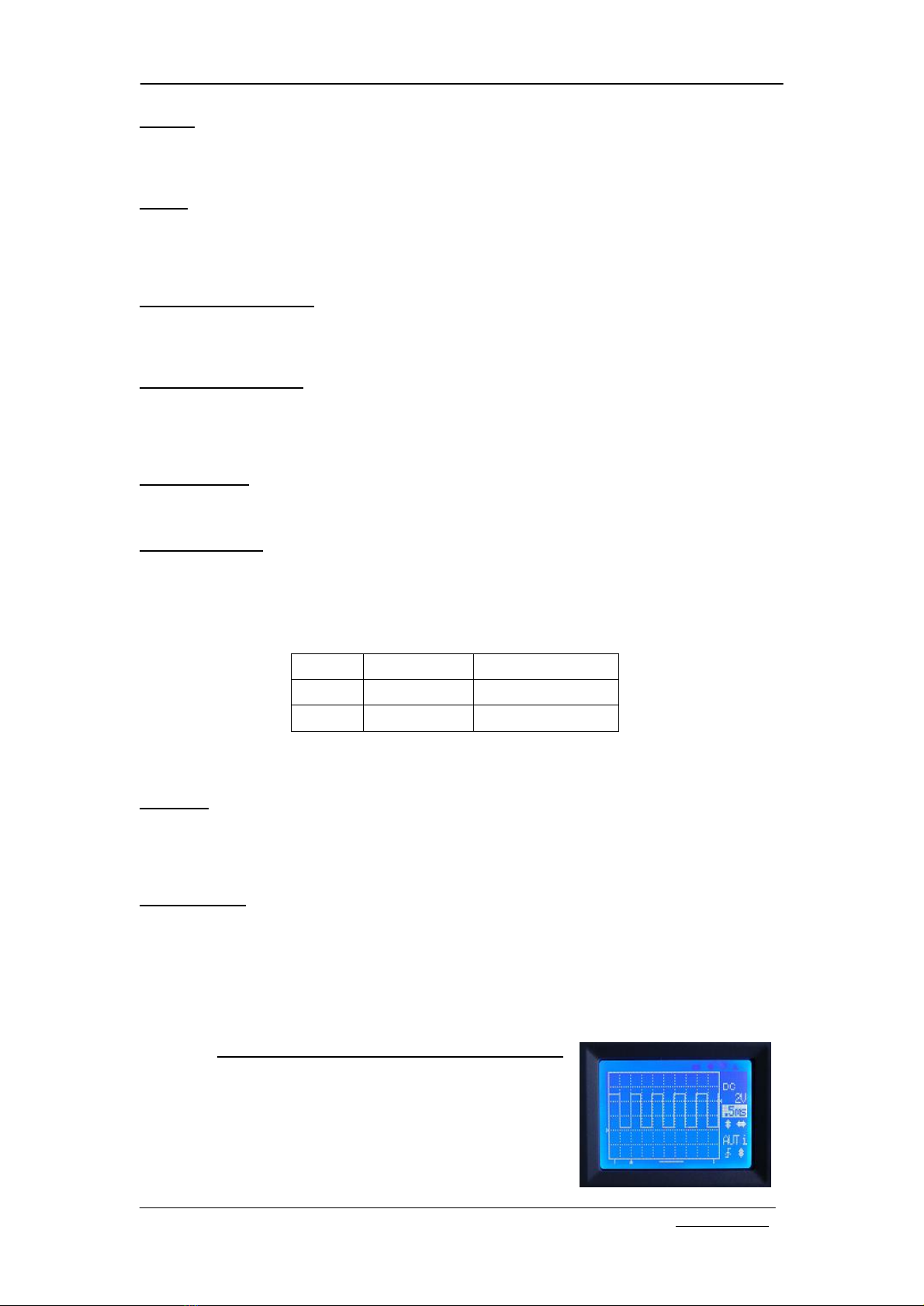
Fig 7
Fig 8
Vertical Position Zeroing
Sometimes you mayfind the vertical position indicator is not aligned to 0V level trace. This is caused bytwo
factors.
1) Component errors.
2) Interference fromthe ADC clock.
In order toreducethemisalignment a “VerticalPosition Zeroing”function was implemented as workaround on
the DSO082. What it actuallydoes is to add correction values to samples so that misalignment does not appear to
be that large. However,even withthiscorrection somemisalignment stillexists (varies depending on Time-base
settings between 1 3pixels,). This misalignment causes someinconvenience but will not affect the measurement
results. Users can use the VPos triangle as arough indicatoronly.Use where the 0V level is as areference point
and start measurements fromthere.
Touse the “Vertical Position Zeroing”function first set the coupling switch to the “GND”position. Then press
[VPOS]button and hold itdownfor about 3seconds.The VPos zeroing prompt screen will appear.Followthe
instructions on the screen to continue.
Please note thatvertical position zeroing isdependent upon theindividual Time-base setting. Thismeans that
for each Time-base setting there is aspecific correction value, which the zeroing process generates for that
individual Time-base. But 1ms/Div Time-base is special. Zeroing carried under 1ms/Div will set all corrections to
the samevalue. So for anewoscilloscopevertical position zeroing shouldbe first done to1ms/Div.Usuallyonce
zeroing under1ms/Div is doneVPos alignments for most ofthe rest Time-base settings are ok. Ifthe misalignment
is found too large for an individual Time-base, then you should carry out zeroing for that Time-base.
Rolling Display Mode
When Time-base is set to 0.1s/Divor slower DSO 082 uses adisplaymode called “Rolling”.In thismode the
trace shifts fromright to left, simulating time passing.
LCD Backlight ON/OFF
Pressing [MODE]and [LEVEL]at the sametimewill toggle the LCD backlight ON/OFF.This is useful when
the oscilloscope is running on batterypower.
PowerOff
Topower offthe oscilloscopepushdownthe adjustment knob and holditfor about 3seconds. The oscilloscope
will enter stand-bymode where most ofcircuits are powered off. Onlykeypad remains active.
6. Advanced Operations
Select Record Length
In normal running mode pushing and holding downthe [HPOS] button
will make the device enter the Record Length Selection screen (see Fig 7).
Use the adjustment knob to select the record length you want and press
[HOLD]to Exit and return to normal running mode.
Formost applicationsrecord length of2000 points isenough and is thus
recommended. This will allowthe oscilloscope response timeto be faster.If
alonger record length is selected the slower the response will be expected
because the device needs more timeload the buffer before starting anew
captured signal sample. Particularly,when the Time-base is set to 20ms/Div
or 50ms/Div and the record lengthof10000 or larger is selected; you will see
a significantlyslower displayupdate.
Change TriggerPosition
In normal running mode pushing and holding downthe [LEVEL] button
will make the device enter theTrigger Position selection screen (see Fig 8).
Use the adjustment knob toselect the trigger position you want and pressing
the [HOLD]button Exits and returns to normal running mode.
The Trigger position can beset to1/8, 1/4, 1/2, 3/4, or 7/8 in the captured
signal sample buffer (regardless ofrecord length setting). Ifthe trigger
position is setto 1/8 this means the first 1/8ofthebuffer keeps the sample
taken before trigger point, and 7/8 ofthe buffer keeps asample taken after
the trigger point. Ifthetrigger position is setto 1/2 this means buffer size
used tokeep samples before and after trigger point is halfand half.Apparently,
ifyou are more interested inwaveformsafter the trigger point you shouldset thetrigger position to a smaller value.
And ifyou are more interested in a signal before the trigger then a larger trigger position setting should be used.
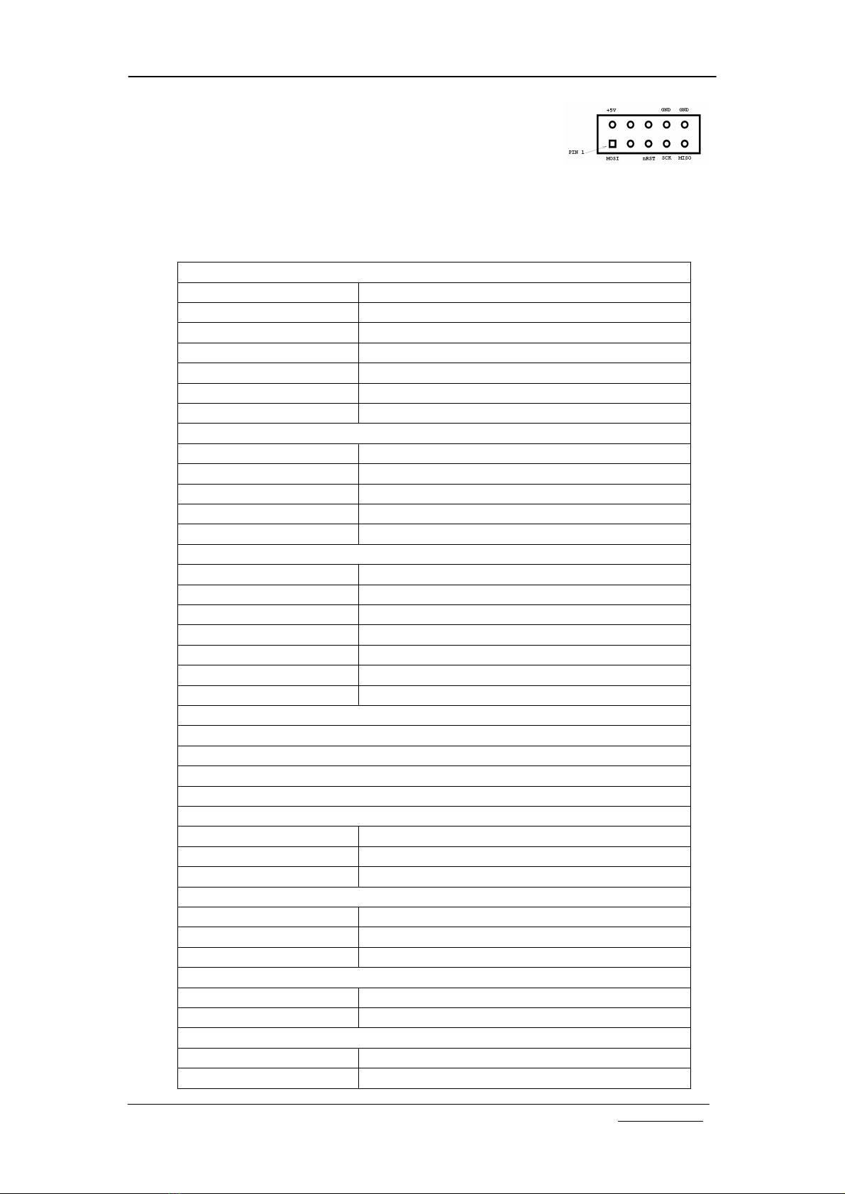
USBConnection
The USB connection used in082 is avirtual Uart portbased on the dedicated Uart-USB convert chip CP2102
fromSilicon Lab. Tousetheconnection, you need to installthe PC drivers. Drivers for Windowsand Linux can be
downloaded fromthe Silicon Lab’s web site.

DN082-02v02
JYE Tech - 6 - www.jyetech.com
Fig 9
Fig 10
Fig 11
Download link: http://www.silabs.com/products/mcu/pages/usbtouartbridgevcpdrivers.aspx
Save captured signal samples
Captured waveforms can be stored in the on-chip EEPROM for later use.
Do This by:
1) Freeze the waveformyou intend to save bypressing [HOLD]key
(enter HOLD state).
2) Press [SLOPE]and use [KNOB]to select one ofthe 4 buffers.
3) Press [VPOS]to enter save captured signal sample screen.
4) Press [HOLD]to save the frozen waveformto the buffer selected.
Recall captured signal samples
To recall saved waveforms:
1) Enter HOLD state bypressing [HOLD].
2) Press [SLOPE]and use [KNOB]to select the buffer to be recalled.
3) Press [HOLD]to displaythe waveformin the buffer selected.
Send Screen as Bitmap File
The oscilloscopescreen can be transferred to aPCas abitmap file via the
USB. The transfer protocol used here is Xmodem.Communication format is
38400bps,8data bits, 1stop bit,no parity,no flowcontrol. Todo this, please
followthe steps below:
1) Install Virtual ComPort driver ifyou have not alreadydone so.
2) Connect the scope to PC via a mini USB cable.
3) Launch WindowsHyperTerminal (or anyother communication tool
that can handle the Xmodemprotocol) and prepare it to receive a file.
Select file extension nameto be “.bmp”.Otherwise the file cannot
be openedproperly.Ifyou failed to do so inthis step you can always renamethe file to “.bmp”so that
it can be opened.
4) Put scope into HOLD state and displaythe waveformyou are interested in on the screen.
5) Press the [LEVEL]button, then [HOLD]. Scope screen will be sent to PC as a bitmap file.
Using theExternal Trigger
1) ToSelect the triggersource, Press [LEVEL]tohighlight the trigger level indicator.Press [LEVEL]
again to select the trigger source. For the external trigger,press the[LEVEL]button so that letter “e”is
displayed.
2) Connection of external triggersignal. Connect the external trigger signal to the M.F.T.Note: external
trigger signal amplitude should not exceed the allowed range of0 -+10V.
3) Connect signal to be viewed to the oscilloscope input.
4) Adjust triggerlevel to generate trigging.
Note: External trigger signal is taken as adigital signal. The trigger threshold is LVTTL, i.e. voltage of
0.8Vor lower is considered as LOWand voltage of2.0Vand higher is considered HIGH.
Using theFFT
1) In normal oscilloscope mode. Enter FFTmode byholding the
[MODE]button down for 2 3 seconds.
2) Use [HPOS]to select FFTsize (256, 512, or 1024).
3) Use [KNOB]to select sampling rate.
4) To return to oscilloscope mode press the [MODE] button again.
5)
7. Firmware Upgrade
The main firmware is run byMCU ATmega64. There are two ways to upgrade this firmware.
1) Using the pre-programmed bootloader. (See Section 5 Power up)
2) Using hardware programmer.
For using the bootloader you onlyneed aminiUSB cable and an application running on aPC.This is the
easiest and saftest wayso it isstronglyrecommended. For Windowsusers, the PCapplication is “avrubd.exe”
from Shao Ziyang (http://blog.ednchina.com/shaoziyang/). Please download thisprogramfromJYE Tech web
site and copyit toyour computer(no installation required).Refer to thedocument “Howto Programthe Scope”
for more detailed operation procedures.

DN082-02v02
JYE Tech - 7 - www.jyetech.com
Fig 12 J3 pin-out
Ifhardware programmer is used, it isimportantto make sure the programmer
has acompatiblepin-out. Iftheyare different you need tore-routethesignals to
match the pinouts. The programming header for ATmega64 (U2) is J3. Its pin-out
is shown Fig 12 and is also indicated on the PCB.
IfJYE Tech’sUSB AVRProgrammer (PN: 07302) is used toprogramthe
oscilloscope remember to connect programming ribbon cable toheader J5 on
07302 board. Do not connect to J8, This is for the older 062 models only.The first
conductorofthe ribbon cable (usuallymarked with red stripe along one edge) shouldbe alignedtoPIN1of
headers on both boards. Programoperators should then followthe instructions oftheir respective programmers.
8. Specifications
Vertical
Number ofChannels One
Analog Bandwidth Range 0 10MHz
Sensitivity10mV/Div 5V/Div
Resolution 8 bits
Input Impedance 1M Ohm
Max InputVoltage 50Vpp (for 1Xprobe)
Couple Range DC, AC, GND
Horizontal
Max Real-time Sample Rate 50MSPS
Time-base Range 0.2us/Div 10minute/Div
Record Length 2000 16000 points user selectable in steps of2000 points
Zoom-In Up to 10 times in HOLD mode
RUN/HOLD Modes One button switchable
Trigger
Trigger Modes Auto, Normal, and Single
Trigger PolarityRising/Falling
Trigger Source Internal, External
Trigger position 1/8, 1/4, 1/2, 3/4, or 7/8 ofsample buffer user adjustable
Trigger Point Indicator Yes
External Trigger Input Range 0 10V
External Trigger Threshold LVTTL
OtherFeatures
Save/recall up to 4captured signalsample s
Screen image hardcopy
Firmware upgradeable via bootloader. No programmer needed
USB connection for data transfer and firmware upgrade
FFT
FFTSize 256, 512, or1024 points selectable
FFTSampling Rate 1KSps 50MSps adjustable
WindowHamming
Display
Screen 2-inch 128 X64 dot-matrix black/white LCD
Backlight Yes (ON/OFF controllable)
Contrast Adjustable
PowerSupply
Power SupplyVoltage 9 DC
Power SupplyCurrent < 200mA
Physical
Dimension 140mm X70mmX30mm
Weight 150 grams (not including probe and power adapter)

DN082-02v02
JYE Tech - 8 - www.jyetech.com
9Limited Warranty
JYE Tech Ltd. warrant the DSO082 oscilloscope against defects in materials and workmanship under ordinary
consumer use for aperiod of one year fromthe date oforiginal retail purchase. During this warrantyperiod, ifa
fault occurs with the oscilloscope,and the customer follows the instructions for returning the oscilloscope, Wewill,
to the extentpermitted bylaw,offer one ofthe following options:(i)repairtheoscilloscopeusing either newor
refurbished parts, (ii) replace the oscilloscope with a newor refurbished one, or(iii) refund to you, all or part ofthe
purchase price oftheoscilloscope. All replaced partsand oscilloscopes for which arefund has been given shall
becomethe propertyofJYE Tech Ltd. This limited warrantyapplies onlyto the hardware components ofthe
oscilloscope that have not been subjected to: accident, misuse, neglect, fire or other external causes, alternations,
repair, or commercial use.
For information on howto obtain a warrantyservice for your oscilloscope, please contact JYE Tech at
support@jyetech.com.
10 Revision History
Version Date Summary
v01 2011.01.23 First release
v02 2011.01.25 Corrected a fewtypo errors
Table of contents