Mennekes TwInlet Type F User manual

Test box models
TwInlet Type F, TwInlet Type E,
TwInlet Universal for charging stations
On ships and
terminals
Giam, sequi bla
quam quat. Tat.
Ibh ero dolendre
Operating manual
Version: 10/2017 - 03
About this document
Explanation of safety symbols
DANGER!
Indication of a
high-risk hazard!
Failure to comply with the information will directly result
in death or major injury.
WARNING!
Indication of a
medium-risk hazard!
Failure to comply with the information can result in death
or major injury.
CAUTION!
Indication of a
low-risk hazard!
Failure to comply with the information can result in minor
to moderate injury.
NOTICE
Indication of a
low-risk hazard!
Failure to comply with the information can result in the
product
being damaged or destroyed.
Translation of the original German-language manual.
Must be read and kept in a safe place.
Protected by copyright.
Duplication, reproduction or transmission, in whole or in
part, only with written consent.
We reserve the right to make technical changes geared
towards improving the product.
Document symbols
fRequired action
Listing
9Check
Tip
ÎReference to another part of this document
Reference to separate documents that need to be com-
plied with
2

Table of contents
1. For your safety................................................... 4
1.1 Intended use ....................................................... 4
1.2 Target group ........................................................ 4
1.3 General safety information ................................... 4
1.4 Operating position................................................ 5
1.5 Service.................................................................. 5
2. Device overview ................................................ 5
2.1 Scope of delivery .................................................. 5
2.2 Features and variants............................................ 5
2.2.1 TwInlet Type F............................................ 6
2.2.2 TwInlet Type E............................................ 6
2.2.3 TwInlet Universal ........................................ 7
2.3 Technical data ...................................................... 7
2.4 Nameplate............................................................ 7
3. Setting-up process............................................. 8
4. Operation ........................................................... 8
4.1 Charging mode 3 ................................................. 8
4.1.1 Status A ..................................................... 8
4.1.2 Status B...................................................... 8
4.1.3 Status C ..................................................... 9
4.1.4 Status D ..................................................... 9
4.1.5 Status E.................................................... 10
5. Troubleshooting .............................................. 10
6. Storage and disposal....................................... 11
6.1 Storage............................................................... 11
6.2 Disposal.............................................................. 11
7. Appendix.......................................................... 11
7.1 Accessories......................................................... 11
7.2 Glossary.............................................................. 11
3

1. For your safety
1.1 Intended use
MENNEKES test boxes simulate the charging process for
electric vehicles at charging stations.
Mode 3 charging according to IEC 61851-2:2017.
Plugs and sockets according to IEC 62196.
Test boxes are used to check MENNEKES charging stations.
“Intended use” also includes compliance with the require-
ments for installation, operation and servicing set out by
MENNEKES.
Any other use is regarded as improper use and is not
permitted.
1.2 Target group
Qualified electrician
The device is intended to be used exclusively by an electri-
cian.
The electrical, moreover, must have a recognised qualifica-
tion in electrical engineering. On account of his or her spe-
cialist knowledge, the electrician is authorised to carry out
the tasks described in this manual.
Requirements to be met by the qualified electrician:
Knowledge of general and special regulations pertaining
to safety and accident prevention.
Knowledge of relevant electrotechnical regulations (e.g.
DIN VDE 0100-600, DIN VDE 0100-722).
Ability to identify risks and avoid possible hazards.
DANGER!
Risk of death from electrocution!
Some components are live.
Contact with live parts will result in
electric shock, burns or death.
fIt is essential to comply with the safety information
and instructions in this document.
Use of the device is prohibited:
if explosive or highly flammable materials are stored
nearby.
if the device is standing in water.
for ambient temperatures below -20°C or above 40°C.
in case of damage to the device or individual compon-
ents.
for children and persons who are not able to accurately
assess the hazards associated with using the device.
MENNEKES accepts no liability for damage in the following
cases, all of which result in the guarantee for the device
and accessories becoming null and void.
Failure to comply with the information in this operating
manual.
Improper use.
Incorrect handling.
Deployment of unqualified personnel.
Modification or conversion of the device.
Use of spare parts not manufactured or approved by
MENNEKES.
Use of high-pressure cleaners or sandblasters.
1.3 General safety information
4
During operation, the position of the device must be
checked and the positioning requirement complied with.
The test box must be positioned on its rear face, so that
the hinged socket lids open in an upward direction and the
plugs of the consumers can be connected.
1.5 Service
The device was in perfect working order at the time it left
the factory.
fIn the event of complaints regarding the device, please
contact MENNEKES or your responsible service partner
immediately.
ÎContact details on the rear of the device.
fPlease have the following information ready at hand:
type designation / serial number;
date of manufacture;
reason for complaint;
duration of use;
ambient conditions (temperature, humidity).
΄2.4 Nameplate“
1.4 Operating position
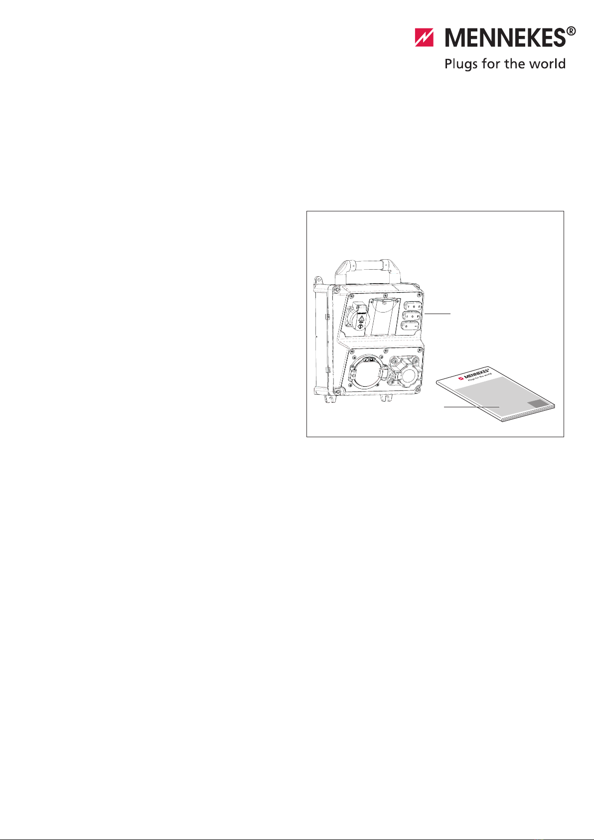
2.1 Scope of delivery
2.1 / 1
A
B
A Test box
B Operating manual
2.2 Features and variants
Simulation of a charging process for an electric vehicle.
Setting options for vehicles with gassing and non-gas-
sing batteries.
Simulation of an alternating current load via connected
external consumers.
Simulation of a defective line.
Residual current device test using an external measuring
instrument.
Meter test via connected external consumers.
Displays indicating failure of protective devices.
Suitable for type-1 and type-2 plugs
System monitoring
Check of rotating field
Check for phase failure
Check for undervoltage
Check of PWM signal via external measuring instrument
΄7.2 Glossary“
2. Device overview
5
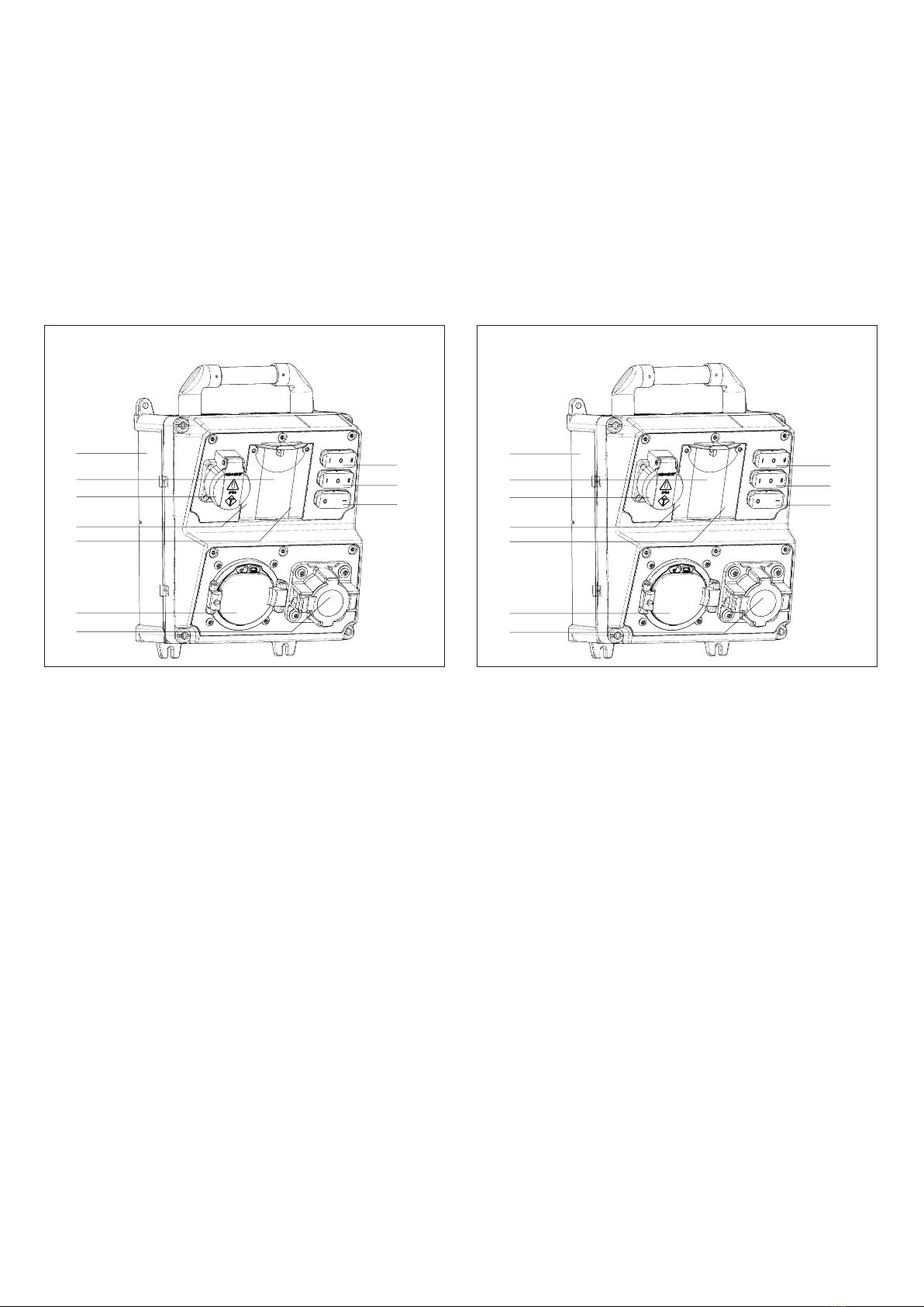
2.2.1 TwInlet Type F
2.2.1 / 1
A Basic enclosure
B Rocker switch for selecting vehicle inlet
C Rocker switch for ventilation requirement
D Rocker switch for fault message
E Fuse protection for SCHUKO®socket
F SCHUKO® socket
G System monitor
H BNC connection point
I Type-2 vehicle inlet (mode3)
J Type-1 vehicle inlet (mode 3)
2.2.2 TwInlet Type E
2.2.2 / 1
A Basic enclosure
B Rocker switch for selecting vehicle inlet
C Rocker switch for ventilation requirement
D Rocker switch for fault message
E Fuse protection for Type E socket
F Type E socket
G System monitor
H BNC connection point
I Type-2 vehicle inlet (mode3)
J Type-1 vehicle inlet (mode 3)
B
C
D
A
E
F
G
H
I
J
B
C
D
A
E
F
G
H
I
J
6

2.2.3 TwInlet Universal
2.2.3 / 1
A Basic enclosure
B Rocker switch for selecting vehicle inlet
C Rocker switch for ventilation requirement
D Rocker switch for fault message
E Fuse protection for CEE socket
F Single-phase CEE socket
G System monitor
H BNC connection point
I Type-2 vehicle inlet (mode3)
J Type-1 vehicle inlet (mode 3)
B
C
D
A
E
F
H
J
G
I
2.3 Technical data
Nominal voltage 230VAC (±10%)
400VAC (±10%)
Nominal frequency 50Hz
Nominal current 10 A
Maximum back-up fuse rating 80 A
Protection class IP 20
Dimensions (H x W x D) 260 x 225 x 165 mm
Weight 3.3 kg
2.4 Nameplate
The nameplate can be found on the rear of the device.
2.4 / 1
Information on the nameplate:
Manufacturer
Type
Serial number
Date of manufacture
Nominal current
Nominal voltage
Nominal frequency
Protection class
Test box
Type ser. no.: 320013.00001
Manuf. date: 1/2/2013
10 A 230/400 V 50 Hz IP 20
7
3. Setting-up process
Requirements at the place of operation
DANGER!
Risk of death due to improper use
Failure to comply with the specifications for the ambient
conditions can lead to hazardous situations when working
with electricity.
fEnsure that the requirements at the place of operation
are adhered to at all times.
Device not to be used in potentially-explosive
atmospheres
(e.g. at gas filling stations).
Compliance with the local technical connection require-
ments and safety rules.
Maximum humidity (non-condensing): 95 %.
Ambient temperature between -20°C and +40°C,
mean temperature over 24-hour period < 35 °C.
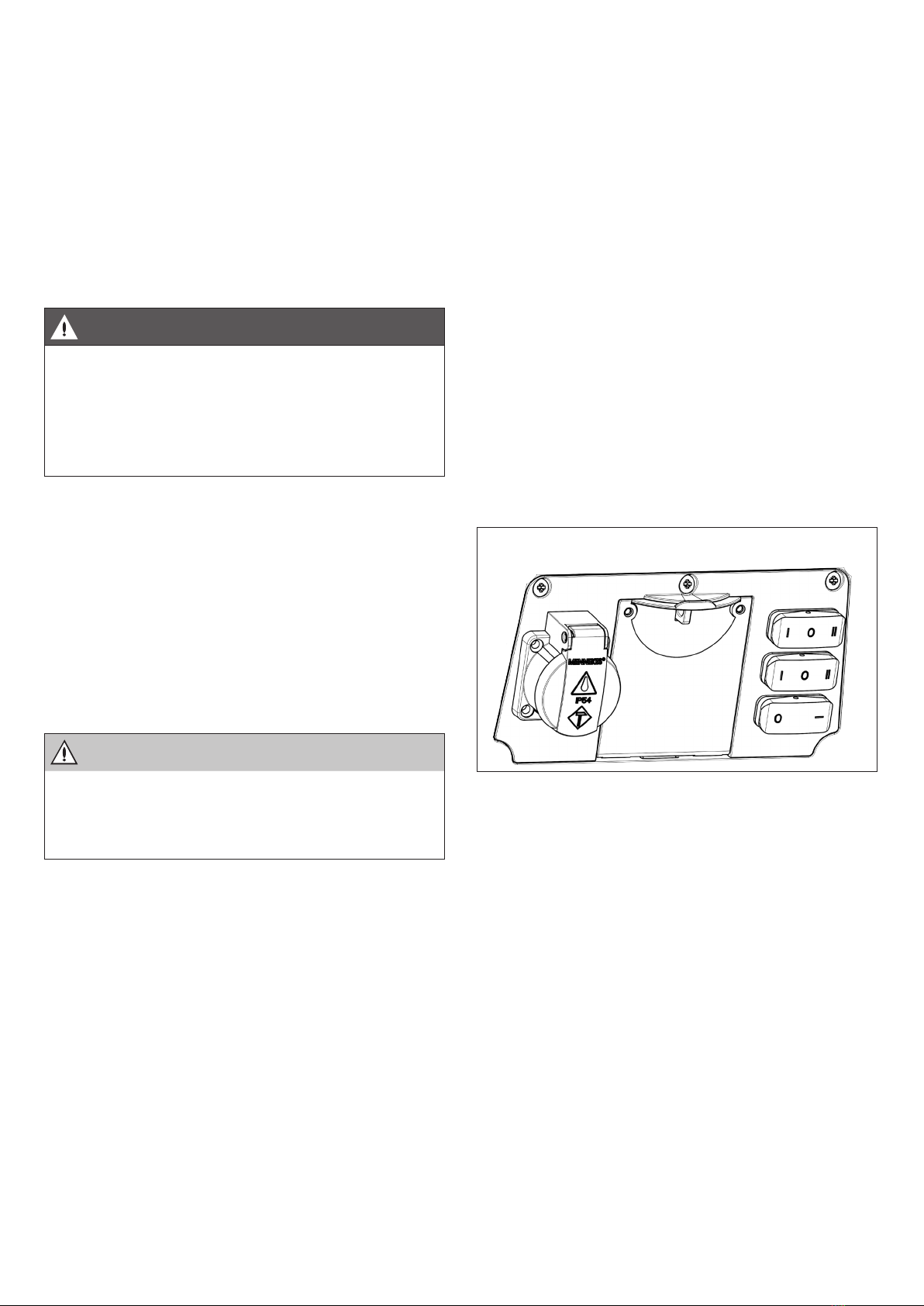
4. Operation
CAUTION!
Hazard due to improper use
An open charging inlet can become contaminated
)Close the lid of the charging inlet not in use.
4.1 Charging mode 3
Have the documentation on the charging station handed
out by the operator. The documentation can also be
found at the MENNEKES website
(www.MENNEKES.de).
The test box simulates the charging statuses of an electric
vehicle. Consequently, the test box acts like an electrical
vehicle in this manual.
The device has rocker switches which can be used to set
the various charging statuses and test certain functions of
the charging system; this is achieved by selecting the switch
positions accordingly. The positions of the rocker switches
are indicated in the diagrams below.
fInsert the charging plug fully in the type-1 or type-2
charging socket at
the test box. Use one charging inlet only at all times
fConnect the charging cable to the MENNEKES charging
station.
fSet the three rocker switches according to the vehicle
status (one of A - E) that you wish to simulate. Note the
information below in this regard.
4.1.1 Status A
Test box connected to charging station
There is no communication between the test box and the
charging station.
4.1.1 / 1
Setting for rocker switches (0)
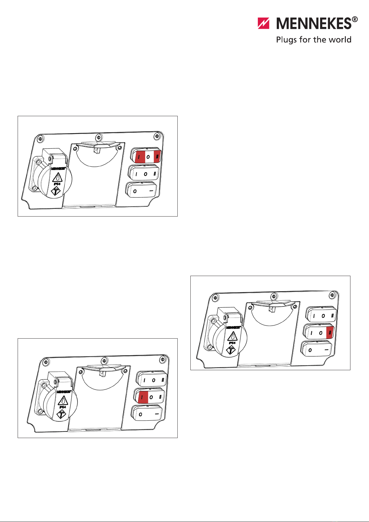
4.1.2 Status B
Test box connected to charging station
Communication between the test box and the charging sta-
tion is established.
Charging socket (type 1 or type 2) selected via setting for
top rocker switch.
Switch setting I corresponds to a charging inlet of type 2
(left side).
Switch setting II corresponds to a charging inlet of type 1
(right side).
The test box simulates the charge readiness state of the
vehicle.
8
4.1.4 Status D
Test box simulation of charging process for vehicle
with gassing battery
Caution: For status D, external ventilation of the vehicle
surroundings is essential for the charging process. A vehicle
can be charged if the place of charging is sufficiently ven-
tilated. The ventilation requirement at the charging station
has to be satisfied with the appropriate setting.
For information on the ventilation requirements,
please refer to the operating manual provided for the
MENNEKES charging station.
For a single-phase charging cable, the L1 LED of the system
monitor lights up.
For a three-phase charging cable, all 3 LEDs (L1, L2, L3) of
the system monitor light up.
4.1.4 / 1
Setting for middle rocker switch (II)
4.1.2 / 1
Setting for top rocker switch (I or II)
4.1.3 Status C
Test box simulation of charging process for vehicle
with non-gassing battery
For status C, external ventilation of the vehicle surroundings
is not required for the charging process. The charging pro-
cess for a vehicle is simulated.
For a single-phase charging cable, the L1 LED of the system
monitor lights up.
For a three-phase charging cable, all 3 LEDs (L1, L2, L3) of
the system monitor light up.
4.1.3 / 1
Setting for middle rocker switch (I)
9
5. Troubleshooting
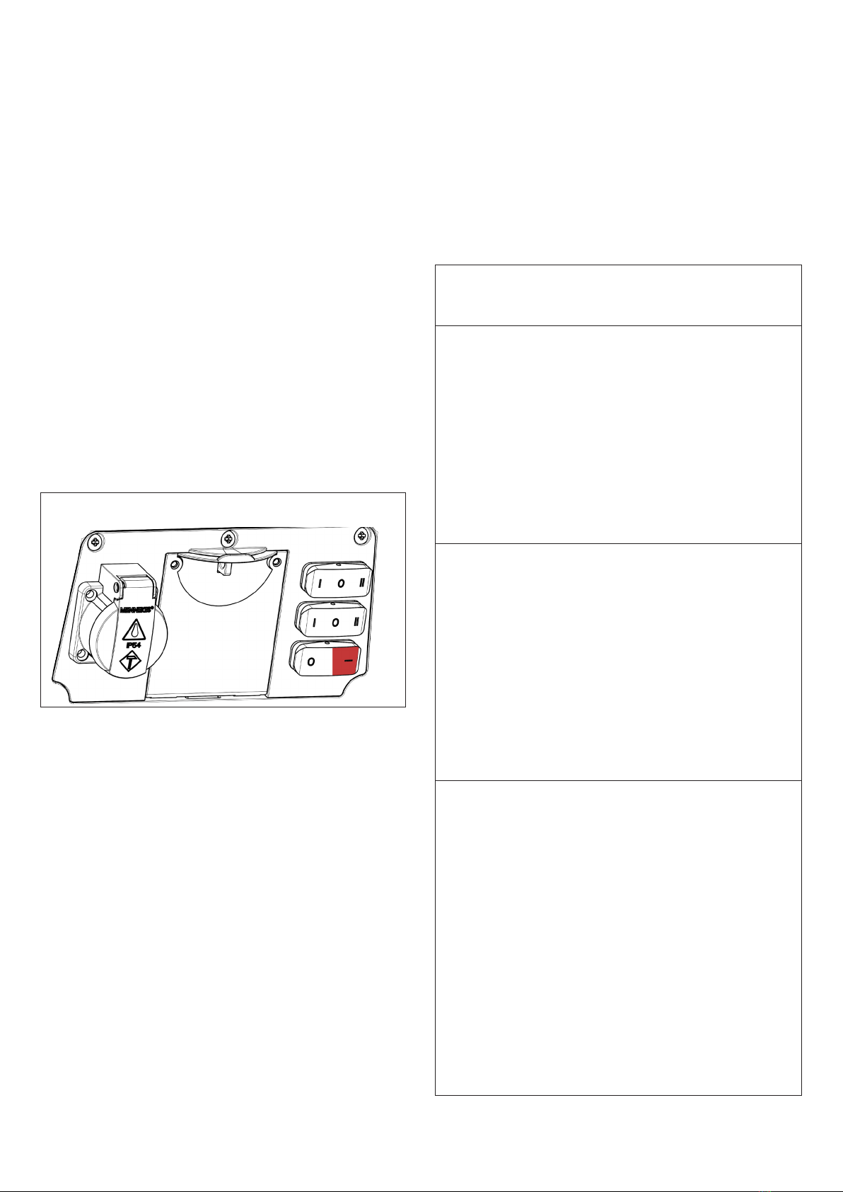
4.1.5 Status E
Simulation of communication fault between test box
and charging station
The charging station indicates a fault. If a charging process
is still active, this will be terminated immediately. For the
“status E” setup, it is not possible to start a charging pro-
cess.
After completing the tests or for the purpose of starting a
new charging process:
fRemove the charging cable.
4.1.5 / 1
Setting for bottom rocker switch (I)
Fault Description
Fault cause
fFault remedy
1Test box does not respond
No supply of power to charging sys-
tem.
fCheck the power supply.
Charging plug not correctly inserted.
fCheck the plug-in connection.
Incorrect vehicle status set.
fCheck the switch settings for the
respective status (one of A-E).
Incorrect charging cable current.
fUse a suitable charging cable.
2Control lamps of system monitor do
not light up
No supply of power to charging sys-
tem.
fCheck the power supply.
Charging plug not correctly inserted.
fCheck the plug-in connection.
Incorrect vehicle status set.
fCheck the switch settings for the
respective status (one of A-E).
Incorrect charging cable current.
fUse a suitable charging cable.
3System monitor indicates
a faulty operating state
Anticlockwise rotating field (LEDs flash in
reverse order)
Phases are swapped.
fCheck the power supply connections.
fMake corrective adjustments for the
swapped connections.
Phase failure (one or several LEDs are
off).
Failure of a phase.
fCheck the phase according to the cir-
cuit diagram.
fCheck whether residual current
devices and MCBs are activated.
fCheck the power supply line.
10

7. Appendix
Fault Description
Fault cause
fFault remedy
4Low voltage (one or several LEDs are
flashing)
Voltage of corresponding phase too
low.
fCheck the power supply.
fCheck the neutral conductor, if
necessary.
fIf, following the check, faults continue to occur, please
contact MENNEKES or your responsible service partner.
ÎSee rear of device for contact details.
6. Storage and disposal
6.1 Storage
Dry and temperature-controlled rooms are to be used for
storage, with the temperature lying between 0°C and
40°C.
6.2 Disposal
Old devices and packaging must be disposed of in accor-
dance with the national and regional laws and standards.
Environmental concerns must be taken into consideration.
Old devices must not be disposed of with household waste.
fDispose of old devices at a collection point for electronic
waste or via your dealer.
fDispose of packaging material in accordance with the
applicable regulations.
7.1 Accessories
Part number Description
36213 Mode-3 charging cable, type 2,
32 A,
3P+N+PE
7.2 Glossary
MCB Miniature circuit breaker
Mode3 (IEC61851) Charging mode for vehicles
with communication interface
at charging sockets of type 1
and type 2.
Type2 (IEC 62196-2) Single- and three-phase char-
ging couplers with identical
plug geometry for charging
powers ranging from 3.7 to 44
kW AC.
Type 1 (IEC 62196-2) Single-phase
charging couplers
for a charging power of 7.4 kW
AC.
BNC connection Co-axial connection with bayo-
net coupling.
11

MENNEKES
Elektrotechnik GmbH & Co. KG
Spezialfabrik für Steckvorrichtungen
Aloys-Mennekes-Str. 1
D-57399 Kirchhundem,
Germany
Tel.: +49 (0) 27 23 / 41-1
Fax: +49 (0) 27 23 41-2 14
www.MENNEKES.de
3331511
All information on application areas, product solutions, basic
knowledge, training courses and discussion guides can also be
found online at our info portal.
Subject to change without notice. No liability accepted for printing errors.
You can also find us on: Facebook, YouTube, Twitter, Xing and LinkedIn
Brochures can be requested by sending an e-mail to:
info@MENNEKES-emobility.de
MENNEKES service telephone number:
+49 (0) 27 23 / 41-600
Further information can also be found at our website
www.MENNEKES-emobility.de
Service by
MENNEKES®
Always well informed.
This manual suits for next models
2
Table of contents
Popular Test Equipment manuals by other brands


Fluke
Fluke OF-500-01 OptiFiber Technical reference handbook

Mityvac
Mityvac MV5532 User and maintenance instructions

Extech Instruments
Extech Instruments PRC10 instructions

Viavi
Viavi NSC-200 user guide

Teledyne Lecroy
Teledyne Lecroy WaveSurfer 4000HD quick start guide

ACE INSTRUMENTS
ACE INSTRUMENTS ACE DA-5000 operating manual