AV-4
AUDIO
AUDIO PFP:28111
System Description
EKS00100
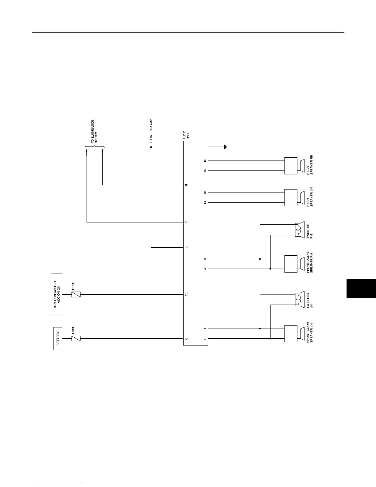
BASE AND MIDLINE SYSTEM
Refer to Owner's Manual for audio system operating instructions.
Power is supplied at all times
●through 15A fuse [No. 31, located in the fuse and fusible link box]
●to audio unit terminal 6.
With the ignition switch in the ACC or ON position, power is supplied
●through 10A fuse [No. 6, located in the fuse block (J/B)]
●to audio unit terminal 10.
Ground is supplied through the case of the audio unit.
Audio signals are supplied
●through audio unit terminals 1, 2, 3, 4, 13, 14, 15, and 16
●to terminals + and - of front door speaker LH and RH
●to terminals + and - of rear door speaker LH and RH
●to terminals + and - of tweeter LH and RH.
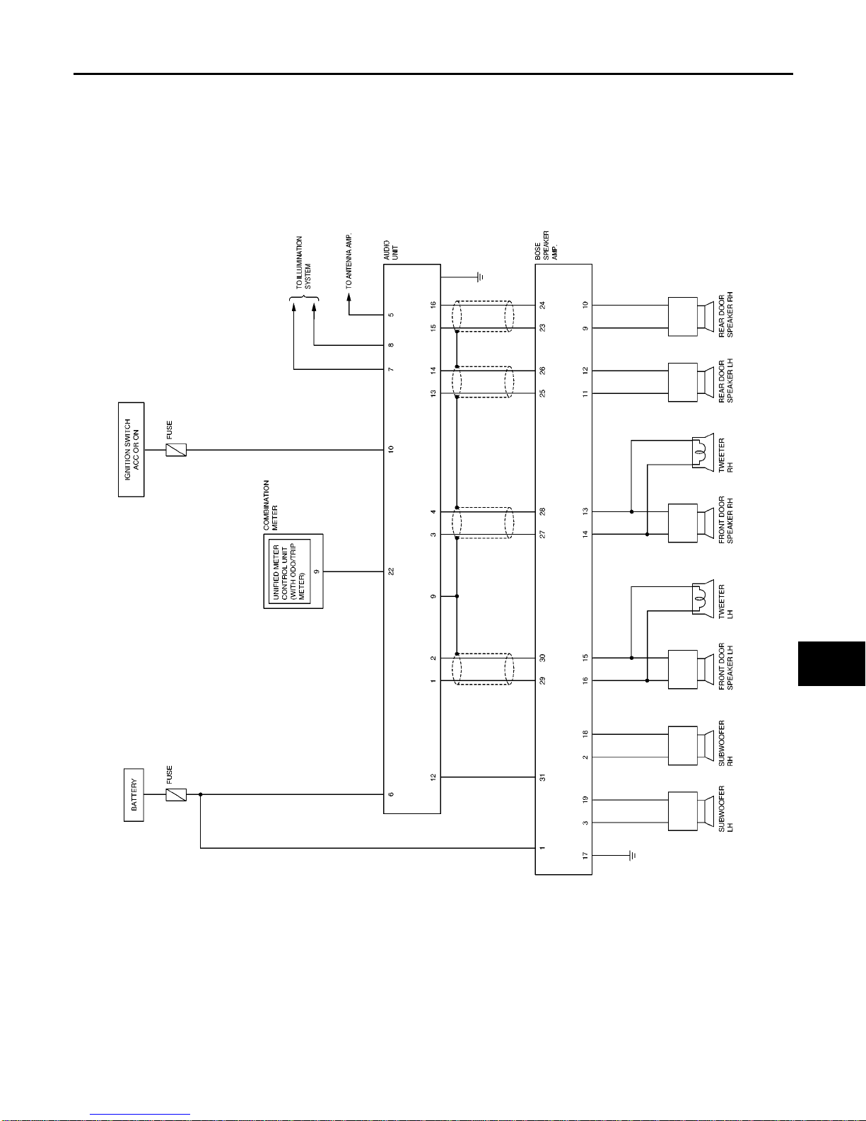
BOSE SYSTEM
Refer to Owner's Manual for audio system operating instructions.
Power is supplied at all times
●through 15A fuse [No. 31, located in the fuse and fusible link box]
●to audio unit terminal 6, and
●to Bose speaker amp. terminal 1.
With the ignition switch in the ACC or ON position, power is supplied
●through 10A fuse [No. 6, located in the fuse block (J/B)]
●to audio unit terminal 10.
Ground is supplied through the case of the audio unit.
Ground is also supplied
●to speaker amp. terminal 17
●through body ground B117.
Audio signals are supplied
●through audio unit terminals 1, 2, 3, 4, 13, 14, 15, and 16
●to speaker amp. terminals 23, 24, 25, 26, 27, 28, 29, and 30.
Audio signals are amplified by the speaker amp.
The amplified audio signals are supplied
●through speaker amp. terminals 2, 3, 9, 10, 11, 12, 13, 14, 15, 16, 18, and 19
●to terminals + and - of front door speaker LH and RH
●to terminals + and - of rear door speaker LH and RH
●to terminals + and - of tweeter LH and RH.
●to terminals + and - of subwoofer LH and RH.
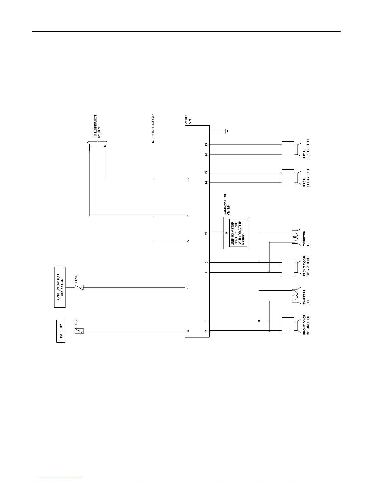
SPEED DEPENDENT VOLUME CONTROL (MIDLINE SYSTEM AND BOSE SYSTEM)
If activated, the radio output volume will be automatically adjusted to compensate for increased driving noises
at higher driving speeds.
The radio receives a vehicle speed signal from the combination meter, and selects the output volume.