K-Factor MSN01-02-03 User manual

MSN01-02-03
Gruppi di continuità monofase
BATTERY BOX
INSTALLAZIONE
MANUALE ISTRUZIONI

Ver.00 07 Febbraio 2019 2
INSTALLAZIONE CABINET BATTERIE x UPS MSN
Ver. 00 – 07.02.2019
GUIDA RAPIDA
1) Place the UPS and BATTERY CABINET close to each other.
Posizionare UPS e box batterie fianco a fianco
UPS CABINET BATTERIE BBT12U

Ver.00 07 Febbraio 2019 3
2) Feed the UPS with the supplied cable and the BATTERY CABINET if is present the plug on the back
Alimentare l’UPS con il cavo di alimentazione fornito e il box batterie con il cavo di alimentazione fornito se la
spina a pannello è presente sul retro dell’unità
3) Open the external battery covers on the UPS and on BATTERY CABINET.
Aprire la protezione esterna del connettore batterie sull’UPS e sul box batterie

Ver.00 07 Febbraio 2019 4
4) Connect the UPS and BATTERY CABINET with special black/red cable.
WARNING: Voltage present on the terminal
Collegare UPS e box batterie con lo speciale cavo rosso/nero fornito. Attenzione: una tensione continua è
presente sul terminale!!!
5) Turn ON the UPS.
Accendere l’UPS

Ver.00 07 Febbraio 2019 5
INSTALLAZIONE CABINET BATTERIE x UPS MSN
1Introduzione
La serie di armadi batterie per UPS MSN è stata progettata per fornire protezione della potenza di qualità a prezzi
eccezionali. I box batterie esterni sono stati progettati con alloggiamenti di batterie rimuovibili e carica batterie
singoli per ottenere la massima efficienza.
2Sicurezza
IMPORTANTI ISTRUZIONI DI SICUREZZA: E’ imperativo conservare queste istruzioni!
Nota: leggete questo manuale prima di installare il battery pack 1-3kVAin quanto contiene importanti informazioni
di sicurezza.
Seguite le istruzioni contenute qui durante l’installazione, per la risoluzione di problemi e la manutenzione dei box
batterie.
Se restano dubbi una volta letto questo manuale, contattate il servizio clienti o il supporto tecnico.
Questo simbolo indica “attenzione”
Questo simbolo indica “Rischio di Shock Elettrico
Questo simbolo indica “fase alimentazione corrente alternata”
Questo simbolo rappresenta “alimentazione a.c.”
Questo simbolo indica “alimentazione corrente continua”
Simbolo “conduttore di terra dell’apparecchiatura”
ATTENZIONE: E’ richiesto, quando si utilizzano cavi AC con il box batterie, che venga utilizzato con cavo 2 poli, tre
fili con terra e spina a tre poli. Il cavo e la spina devo rispettare le normative elettriche locali.
ATTENZIONE: questi box batterie devono essere installati ed operare in un ambiente controllato (0:40°C).
Posizionate il box batterie e l’UPS in in luogo a area che consenta la massima circolazione di aria
PERICOLO: questi box batterie contengono tensioni potenzialmente pericolose. Non tentate di smontare il box
batterie oltre la normale procedure di sostituzione delle batterie. Un utente non dovrebbe mai tentare di riparare
un box batterie, poiché non contiene parti riparabili da un utente. La sostituzione delle batterie e la riparazione
devono essere fatte da personale qualificato
PERICOLO: rischio di shock elettrico. I componenti all’interno del box batterie possono essere alimentati anche
quanto la rete AC è disconnessa.
DE-ENERGIZZAZIONE DEI BATTERY PACK
Attenzione: per de-energizzare i battery pack
1- Se l’UPS è ON, premere e rilasciare il pulsante OFF
2- Scollegare l’UPS e i battery pack dalla presa elettrica
3- Spegnere l’interruttore DC sul pannello posteriore dei Battery pack
4- Disconnettere il cavo delle batterie dal pannello posteriore dell’UPS
5- Per completare la deenergizzazione del Battery Pack, disconnettere le batterie.

Ver.00 07 Febbraio 2019 6
ATTENZIONE: solo personale qualificato può effettuare l’installazione e la messa in servizio di questi battery pack.
Nota: ogni UPS ha differenti tensioni DC e ogni ups è disegnato per supportare uno specifico Battery Pack. Soltanto
l’uso di uno specifico battery pack, indicato sotto, supporta uno specifico UPS. Questi battery pack devono essere
gestiti con i modelli appropriati di UPS
Modello
Battery pack 1kVA
24VDC
Battery pack 2kVA
48VDC
Battery pack 3kVA
72VDC
Modello ups
1KVA
2KVA
3KVA
Attenzione: se si connette un battery pack non coretto con un UPS, potrebbe esserci un forte rischio elettrico.
Verificate sempre che un battery pack sia collegato alla corretta tensione di batteria
ATTENZIONE: CONSERVATE IL MATERIALE DELL’IMBALLO
3Pannello frontale e operazioni
Figura 1 PANNELLO FRONTALE
Il LED di ricarica VERDE indica che il caricabatterie nella batteria esterna si sta caricando normalmente con il cavo
di alimentazione CA collegato alla batteria.
Il LED VERDE del test della batteria indica che l'uscita CC del pacco batteria esterno è normale.
Per eseguire il test della batteria.
•accendere l'interruttore sul retro del pacco batteria
•premere il pulsante Test batteria sul pannello anteriore della batteria
•l'uscita CC dal pacco batteria è normale quando il LED Test batteria è acceso
Prima di collegare il pacco batterie, testare ciascun pacco batterie per accertarne il corretto funzionamento.

Ver.00 07 Febbraio 2019 7
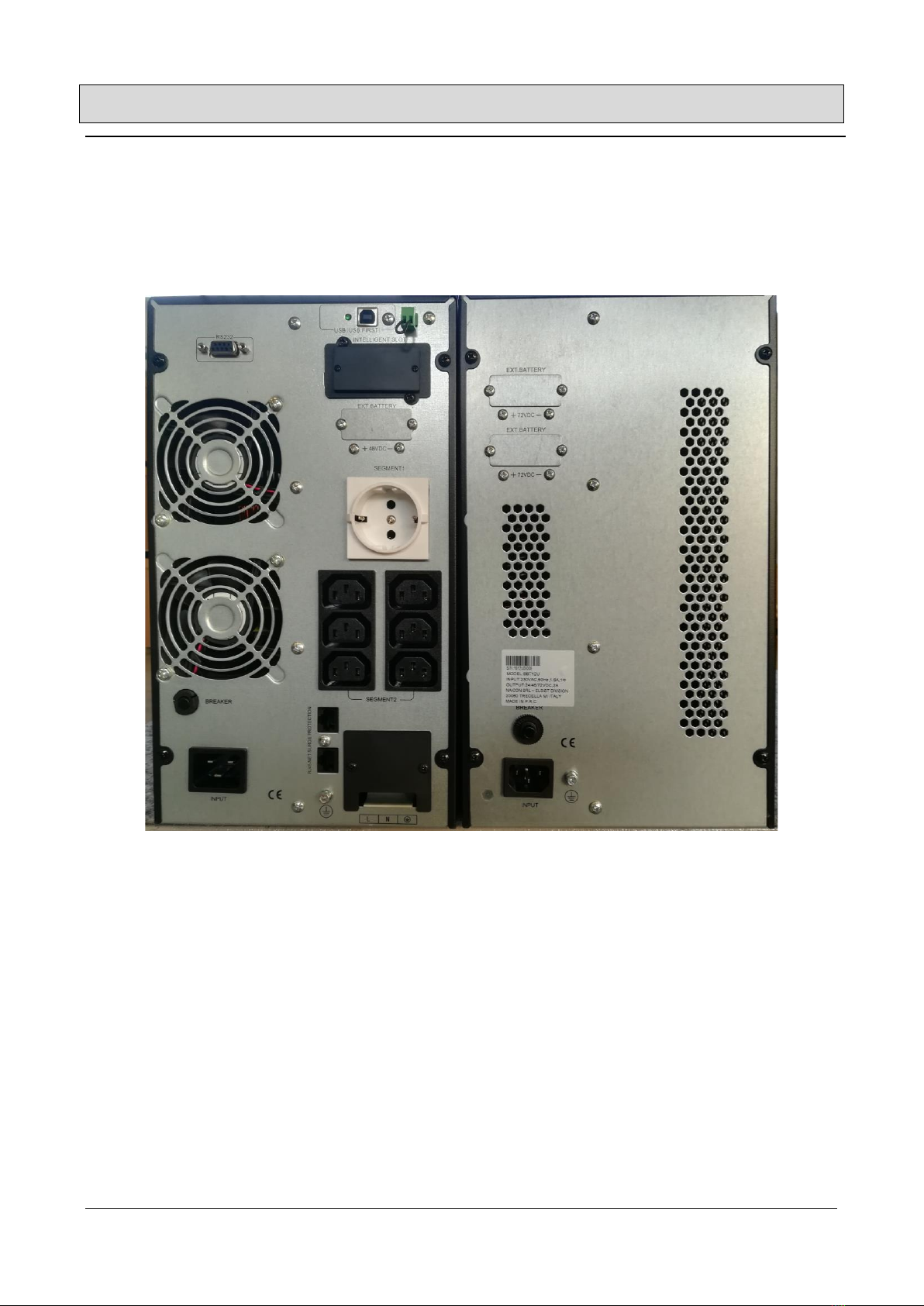
4Descrizione pannello posteriore
Pannello posteriore 1/2/3kVA
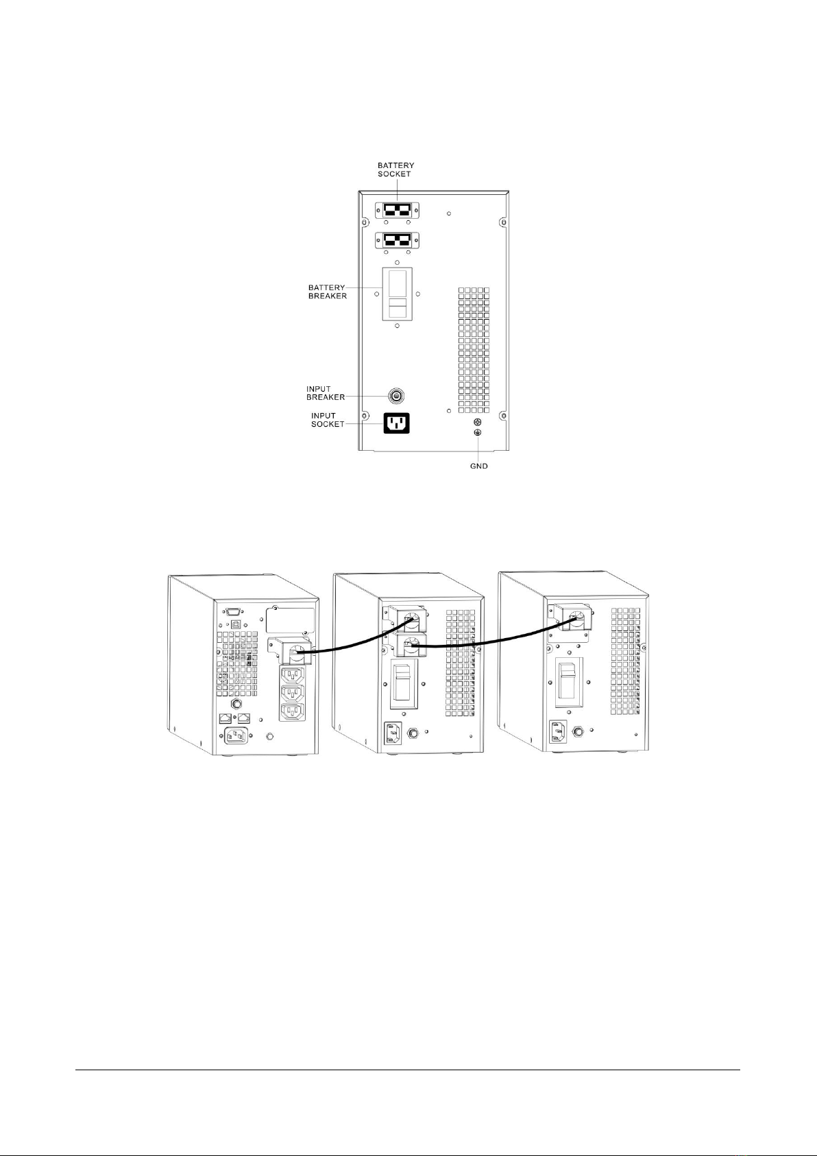
Figura 2 pannello posteriore battery pack 1/2/3kVA
1. L'interruttore automatico CC collega e disconnette la tensione del bus CC dal pacco batteria all'UPS.
L'interruttore automatico CC si disconnetterà in caso di sovracorrente.
2. Il connettore della batteria esterna è per “Daisy Chaining”, ovvero concatenare batterie aggiuntive e / o collegarsi
all'UPS.
3. L'ingresso CA serve per collegare il cavo di alimentazione in ingresso per azionare il caricabatterie.
4. L'interruttore di ingresso CA si disconnetterà nel caso in cui il caricatore interno assorba corrente eccessiva.
5. Il cavo della batteria esterna serve per collegare il pacco batteria all'UPS o al collegamento in serie di pacchi
batteria aggiuntivi.
COLLEGAMENTO DEL PACCO BATTERIA A UNA FONTE DI ALIMENTAZIONE CA.
I pacchi batteria richiedono una tensione di ingresso di 220 V, ogni presa consente di collegare solo il cavo di
alimentazione in ingresso di tre pacchi batteria.
1. Collegare il cavo di alimentazione in ingresso del pacco batteria all'ingresso CA sul pacco batteria.
2. Inserire l'estremità “a spina” del cavo di alimentazione in ingresso per il pacco batteria nella presa a muro CA.
Utilizzare solo una presa a due poli e tre fili con messa a terra. Non utilizzare cavi aggiuntivi, strisce di uscita o
strisce di sovratensione.
3. Attivare l'interruttore automatico CC. A questo punto, l'UPS dovrà essere avviato. Fare riferimento alla procedura
consigliata nel Manuale dell'utente UPS.
NOTA: se si collega più di un gruppo batterie, consultare la sezione Collegamento Daisy chain.
RICARICA DELLA BATTERIA
Se i pacchi batteria sono collegati a una fonte CA e installati correttamente, le batterie interne verranno caricate
quando viene fornita una tensione accettabile. I pacchi batteria devono essere caricati per almeno 6 ore prima
dell'uso.
NOTA: se il pacco batteria sarà fuori servizio o conservato per sei mesi o più, le batterie devono essere ricaricate
per almeno 36 ore ogni sei mesi.
5Collegamento estensione battery pack
Il sistema UPS 1KVA-3KVA può essere collegato a più pacchi batteria estesi per aumentare l'autonomia quando
collegato all'UPS che supporta il carico. La maggior parte dei sistemi UPS è limitata a uno o due pacchi batteria
esterni poiché l'UPS è responsabile della ricarica e non ha la capacità di ricarica per gestire le batterie aggiuntive
per una ricarica completa. Il sistema UPS da 1KVA-3KVA supera questa limitazione dotando ogni batteria estesa
con il proprio caricabatterie, offrendo all'utente un modo per ottenere significativamente più tempo di backup
della batteria. Non c’è bisogno di collegare tutti i cavi di alimentazione in ingresso CA per i pacchi batteria: più
pacchi si collega, più veloce è la ricarica delle batterie.

Ver.00 07 Febbraio 2019 8
1. L'interruttore di circuito CC sul retro del pacco batteria collega e disconnette la tensione del bus CC dal
pacco batteria all'UPS. L'interruttore di circuito CC scatta anche in posizione OFF in caso di sovracorrente
nella batteria.
Figura 3 vista posteriore pacco batterie 1/2/3kVA
2. Il pacco batteria utilizza un cavo spedito con ciascun pacco batteria per realizzare il "daisy chain" insieme
al pacco batteria aggiuntivo al primo pacco batteria collegato all'UPS nel connettore opportunamente
etichettato o per collegare il primo pacco batteria all'UPS.
Figura 4 "Daisy Chain"
3. L'interruttore automatico CA di ingresso scatta in posizione OFF nel caso in cui il caricabatterie interno
assorba corrente eccessiva.

Ver.00 07 Febbraio 2019 9
6Specifiche di sistema
MODELLI BATTERY PACK
1KVA Battery Pack
2KVA Battery Pack
3KVA Battery Pack
INGRESSO
Tensione
220/230/240 VAC
Corrente AC
0.5A
1A
1.5A
Frequenza
50/60 Hz
Protezione ingress
Interruttore resettabile
USCITA
CARICATORE
Tensione DC
27.5 ±0.5V
55.0 ±0.5V
82.5 ±0.5V
Corrente DC
2.0A
Protezione uscita
Fusibile
BATTERIA
Tipo batteria
sigillata, senza manutenzione, con valvola, al piombo
Tipo batteria (EBP)
2 stringhe di (2)
12V 9 AH / 24V
2 stringhe di (4) 12V
9AH / 48V
2 stringhe of (6) 12V 9
AH / 72V
Tempo ricarica
8 ore al 90%
CARATT.
FISICHE
DIMENSIONI
W x D x H (mm)
Dimensioni unità
191*428*337
191*428*337
191*428*337
Dimensioni imballo
642*347*490
642*347*490
642*347*490
Peso unità
18.5kg
27.5kg
36.5kg
Peso imballato
20.7kg
29.7kg
38.7kg
Inclusi nella confezione
Battery pack, manual utente, cavo DC, cavo alimentazione
AC
INDICATORI E
ALLARMI
Display led
LED in carica, LED test batteria

Ver.00 07 Febbraio 2019 11
1. Introduction
The battery pack Series of Products has been designed to provide quality power protection at
outstanding prices. The External Battery Packs have been designed with removable battery
cartridges and individual chargers for maximum value.
72. Safety
IMPORTANT SAFETY INSTRUCTIONS: It is imperative to SAVE THESE INSTRUCTIONS!
NOTE: Please read this manual before installing the 1KVA-3KVA battery pack, model 1KVA battery
pack, 2KVA battery pack, 3KVA battery pack as it provides important safety information. Please
follow the instructions contained herein during installation, troubleshooting and maintenance of the
battery packs. If questions exist after reading this manual, please contact the Customer Service or
Technical Support.
This Symbol indicates “ATTENTION”
This Symbol indicates “RISK of Electrical Shock”
Φ This Symbol indicates “Alternating Current Supply Phase”
This Symbol indicates “Alternating Current Supply”
This Symbol indicates “Direct Current Supply”
This Symbol indicates “Equipment Grounding Conductor”
CAUTION! It is required, when using the AC cords attached to the Battery Packs, that a two pole,
three wire grounded AC wall outlet be utilized. The receptacle and branch protection must comply
with local electrical codes.
CAUTION! These Battery Packs must be installed and operated in a temperature controlled
environment (0-40 degrees Celsius). Place the Battery Packs and UPS in a location or area that will
provide maximum air flow (100mm sides and back).
WARNING: These Battery Packs contain potentially hazardous voltages. Do not attempt to
disassemble the Battery Pack beyond the battery replacement procedure. A user should never
attempt to service a Battery Pack, as they contain no user serviceable parts. Battery replacement
and repairs must be performed by Power or
Qualified Service Personnel, only. WARNING!! Risk of Electrical Shock exists. Components
contained within the Battery Packs may be energized from the battery even when the AC input is
disconnected.
De-energization of the Battery Packs
CAUTION! To de-energize the Battery Pack:
1. If the UPS is on, press and release the “Off” button.
2. Disconnect the UPS and the Battery Packs from the wall outlets.
3. Turn off the DC breaker on the rear panels of the Battery Packs.
4. Disconnect the battery cable from the rear panel of the UPS.
5. For complete Battery Pack de-energization, disconnect the batteries.
WARNING: Qualified Service Personnel ONLY must perform the Installation and Servicing of these

Ver.00 07 Febbraio 2019 12
Battery Packs.
Please Note: Each UPS has different DC bus voltages and each UPS is designed to mate with a specific
Battery Pack. Only use the specific Battery Pack, stated below, with its appropriate UPS. These
Battery Packs MUST be operated with their respective UPS models, see the table below:
Model
1KVA battery pack
24 VDC
2KVA battery pack
48 VDC
3KVA battery pack
72 VDC
UPS Model
1KVAS
2KVAS
3KVAS
Warning! If an incorrect battery pack is connected to a UPS, a severe electrical hazard may happen.
Please always verify the Battery Pack model and the correct DC bus voltage before connection
PLEASE SAVE THE PACKING MATERIALS!
CAUTION: It is very critical to connect the correct voltage battery pack with the UPS intended.
1KVA battery pack is for 1KVA UPS
2KVA battery pack is for 2KVA UPS
3KVA battery pack is for 3KVA UPS
CONNECTING THE INCORRECT BATTERY PACK TO THE UPS MAY RESULT IN DAMAGE TO THE UPS AND/OR
BATTERY PACK, AND THE WARRANTY WILL BE VOIDED.
All battery packs have a different DC voltage configuration intended only for the UPS listed above.
83.Front Panel Description And Operations
Figure 1 Front panel

Ver.00 07 Febbraio 2019 13
LED Description
The Charging LED GREEN indicates that the battery charger in the External Battery Pack is charging
normally with the AC power cord attached to the Battery pack.
The Battery Test LED GREEN indicates that the DC output of the External Battery Pack is normal.
To perform the Battery Test.
•switch on the breaker on the rear of the Battery Pack
•press the Battery Test Button on the front panel of the Battery Pack
•the DC output from the Battery Pack is normal when the Battery Test LED is on
Before connecting Battery Pack, test each Battery Pack to assure proper operation.
9 4.Rear Panel Description
1KVA /2KVA/3KVA Battery pack rear panel
Figure 3 1KVA/2KVA/3KVA Battery pack rear panel
1. The DC Circuit Breaker connects and disconnects the DC bus voltage from the Battery pack to the
UPS. The DC Circuit Breaker will disconnect in the event of an over-current condition.
2. The External Battery connector is for Daisy Chaining additional Battery Packs and/or connecting
to the UPS.
3. The AC Inlet is for connecting the input power cord to operate the Charger.
4. The Input AC Breaker will disconnect in the event that the Internal Charger draws excessive
current.
5. The External Battery cable is for connecting the Battery Pack to the UPS or Daisy Chaining
additional Battery Packs.
CONNECTING THE BATTERY PACK TO AN AC POWER SOURCE
Battery Packs require 220V input voltage, each socket permits only three battery packs’ input power
cord to be plugged in.
1. Connect the Battery Pack input power cord into the AC inlet on the Battery Pack.
2. Insert the “plug” end of the input power cord for the Battery Pack into the AC wall outlet. Only
utilize a two-pole, three-wire grounded receptacle. Do not use additional cords, outlet strips or surge
strips.

Ver.00 07 Febbraio 2019 14
3. Switch on the DC circuit breaker. At this point, the UPS will need to be started. Please refer to the
recommended process in the UPS User’s Manual. NOTE: If connecting more than one Battery Pack
please refer to the Daisy Chaining section.
CHARGING THE BATTERY
If the Battery Packs are plugged into an AC source and properly installed, the internal batteries will
be charged when acceptable voltage is provided. Battery Packs must be charged for a minimum of 6
hours before use. NOTE: If the Battery Pack is going to be out of service or stored for six months or
above, the batteries must be recharged for at least 36 hours every six months.
10 5.Extended Battery Pack Operation
The 1KVA-3KVA UPS System can be connected to multiple extended battery packs to increase the
runtime when connected to the UPS supporting the load. Most UPS Systems are limited to one or
two external battery packs because the UPS is responsible for the recharging and does not have the
recharge capacity to handle the additional batteries to a full recharge. The 1KVA-3KVA UPS System
overcomes this limitation by equipping each extended battery pack with its own charger, providing
the user a way to achieve significantly more battery backup time. Not all of the AC input power cords
for the Battery Pack need to be connected to AC - the more you connect the faster the recharge of
the batteries.
1. The DC Circuit Breaker on the rear of the Battery Pack connects and disconnects the DC bus voltage from
the Battery Pack to the UPS. The DC Circuit Breaker will also trip to the OFF position in the event of an
over-current condition in the Battery Pack.
Figure 4 1KVA/2KVA/3KVA Battery Pack REAR VIEW
2. The Battery Pack use a cable shipped with each Battery Pack to “daisy chain” together additional Battery
Pack to the first Battery Pack being connected to the UPS in the appropriately labeled connector, or for
connecting the first Battery Pack to the UPS.

Ver.00 07 Febbraio 2019 15
Figure 5 Daisy chain
3. The input AC Circuit Breaker will trip to the OFF position in the event that the internal Battery Pack charger
draws excessive current.
11 6. System Specifications
EXTENDED BATTERY PACK
MODELS
1KVA Battery Pack
2KVA Battery Pack
3KVA Battery Pack
INPUT
Voltage
220/230/240 VAC
AC Current
0.5A
1A
1.5A
Frequency
50/60 Hz
Input Protection
Resettable Circuit Breaker
CHARGER
OUTPUT
DC Voltage
27.5 ±0.5V
55.0 ±0.5V
82.5 ±0.5V
DC Current
2.0A
Output Protection
Fuse
BATTERY
Battery Type
sealed, maintenance free, valve regulated, lead acid
Battery Type (EBP)
2 strings of (2) 12V 9
AH / 24V
2 strings of (4) 12V 9AH
/ 48V
2 strings of (6) 12V 9
AH / 72V
Recharge Time
8 hours to 90%
PHYSICAL
Dimensions
W x D x H (mm)
Unit Dimensions
191*428*337
191*428*337
191*428*337
Shipping Dimensions
642*347*490
642*347*490
642*347*490
Unit Weight
18.5kg
27.5kg
36.5kg
Shipping Weight
20.7kg
29.7kg
38.7kg
Included in box
battery pack, User Manual, DC cable, AC input cord
INDICATORS &
ALARMS
LED Visual Display
Charging LED, Battery test LED
Table of contents
Languages: