K.M.E. SPA 240 S User manual

Bedienungsanleitung
User Manual
SPA 240 S SPA 450 S
Stereo Power Amplifier
S-Series

INPUT PARAMETER
0dBm=775mV
(balanced and unbalanced)
BRIDGE
BRIDGESTEREO MONO
SER.NR.
MADE IN GERMANY
KLINGENTHALER
MUSIKELEKTRONIK
GmbH
CH B
CHANNEL B
CH A
CHANNEL A
WARNING!
THIS EQUIPMENT MUST BE EARTHED!
PULL POWER PLUG BEFORE OPENING!
OUTPUT POWER
BRIDGE :
EACH CHANNEL:
8 400VA RMSW
4 225VA RMSW
OUT
IN
INPUT
ACTIVE
SPA 450 S
BRIDGESTEREO MONO
SER.NR.
CHANNEL B CHANNEL A
WARNING!
THIS EQUIPMENT MUST BE EARTHED!
PULL POWER PLUG BEFORE OPENING!
KLINGENTHALER MUSIKELEKTRONIK GmbH
MADE IN GERMANY
CH A
4W
120VA RMS120VA RMS
CH B
4WBRIDGE
8 200VA RMSW
INPUT
ACTIVE
SPA 240 S
Bedienfelder SPS 240S/SPA450S
Anschlußfelder SPS 240S/SPA450S
Control Panels SPA 240S/SPA450S
Contnnection Panels SPA 240S/SPA450S
11
22
33
44
55
6
11
6
7
12
7
8
13
8
99
10 10
11
12
13
Lautstärkeregler Kanal A volume control channel A
volume control channel BLautstärkeregler Kanal B
LED-Anzeige Endstufe an / Schutzschaltung aktiv (Kanal A) LED for power amp on / protect active (channel A)
LED for power amp on / protect active (channel B)LED-Anzeige Endstufe an / Schutzschaltung aktiv (Kanal B)
Netzschalter power switch
Indicator-LED für Kanal B
Indicator-LED für Kanal A
Active-LED für: Lautstärkeregler Kanal B in Funktion
Active-LED für: Lautstärkeregler Kanal A in Funktion
indicator-LED for channel B
indicator-LED for channel A
LED for MONO MODE
Limit-LED für: Interner Begrenzer Kanal B aktiv
Limit-LED für: Interner Begrenzer KanalAaktiv
internal limiter channel B is active
internal limiter channel A is active
LED for volume control channel B is active
LED for volume control channel A is active
LED for BRIDGE MODELED-Anzeige für Betriebsart BRIDGE MODE
LED-Anzeige für Betriebsart MONO MODE
78
910111213 6
78
910111213 6
12 5
3 4
12 5
34
POWER
®SPA 240 S
POWER
®SPA 450 S
CHANNEL A CHANNEL B
LIMIT
MONO
USING
MODE
BRIDGE
LIMIT
PROTECT
POWER ON
ACTIVE ACT.
INDICATOR INDICATOR
0dB
-6
-9
-3
-12
-24
-18
-48
0dB
-6
-9
-3
-12
-24
-18
-48
CHANNEL A CHANNEL B
LIMIT
MONO
USING
MODE
BRIDGE
LIMIT
PROTECT
POWER ON
ACTIVE ACT.
INDICATOR INDICATOR
0dB
-6
-9
-3
-12
-24
-18
-48
0dB
-6
-9
-3
-12
-24
-18
-48
22
22
23
23
24
24
25
25
26
26
27
27
28
2814
14
15
15
16
16
17 18
18
19 20 21
21
FREE GROUND
4,0 AT
230V ~ AC 50-60 Hz
Pn750W
FUSE
FREE GROUND
230V ~ AC 50-60 Hz
Pn370W
16
17
18
19
20
21
22
23
24
14
15
25
26
27
28
Ausgang Kanal B (SPEAKON) (Klinke bei SPA 240 S) (SPA 240 S: jack)
(Klinke bei SPA 240 S) (SPA 240 S: jack)
Ausgang Mono-Brücke (SPEAKON)
LED-Anzeige: Mono Brücke aktiv
nur SPA 450 S only SPA 450 S
Ausgang Kanal A (SPEAKON)
Ausgänge
Eingänge
LED-Anzeige: Ausgang Kanal B aktiv
LED-Anzeige: Ausgang Kanal A aktiv
LED-Anzeige: Eingang Kanal A aktiv
LED-Anzeige: Eingang Kanal B aktiv
Schalter zum Trennen Schaltungsmasse vom Gehäuse
Anschluß für Netzkabel
Umschalter zwischen Stereo-, Brücken- und Mono-Modus
Eingang Kanal A oder Mono-Brücke (XLR)
Eingang Kanal B (Klinke)
Eingang Kanal A oder Mono-Brücke (Klinke)
Eingang Kanal B (XLR)
16
17
18
19
20
21
22
23
24
14
15
25
26
27
28
output channel A (SPEAKON)
output channel B (SPEAKON)
LED: output channel B active
LED: output channel A active
LED: bridge-output active
Outputs
Inputs
mono-bridge (SPEAKON)
switch for disconnect ground from casing
power cord
switch between stereo-, bridge- and mono-mode
input channel A or mono-bridge (XLR)
input channel A or mono-bridge (jack)
input channel B (jack)
LED: input channel B active
LED: input channel A active
input channel B (XLR)

Allgemeine Daten
Anschlußhinweise
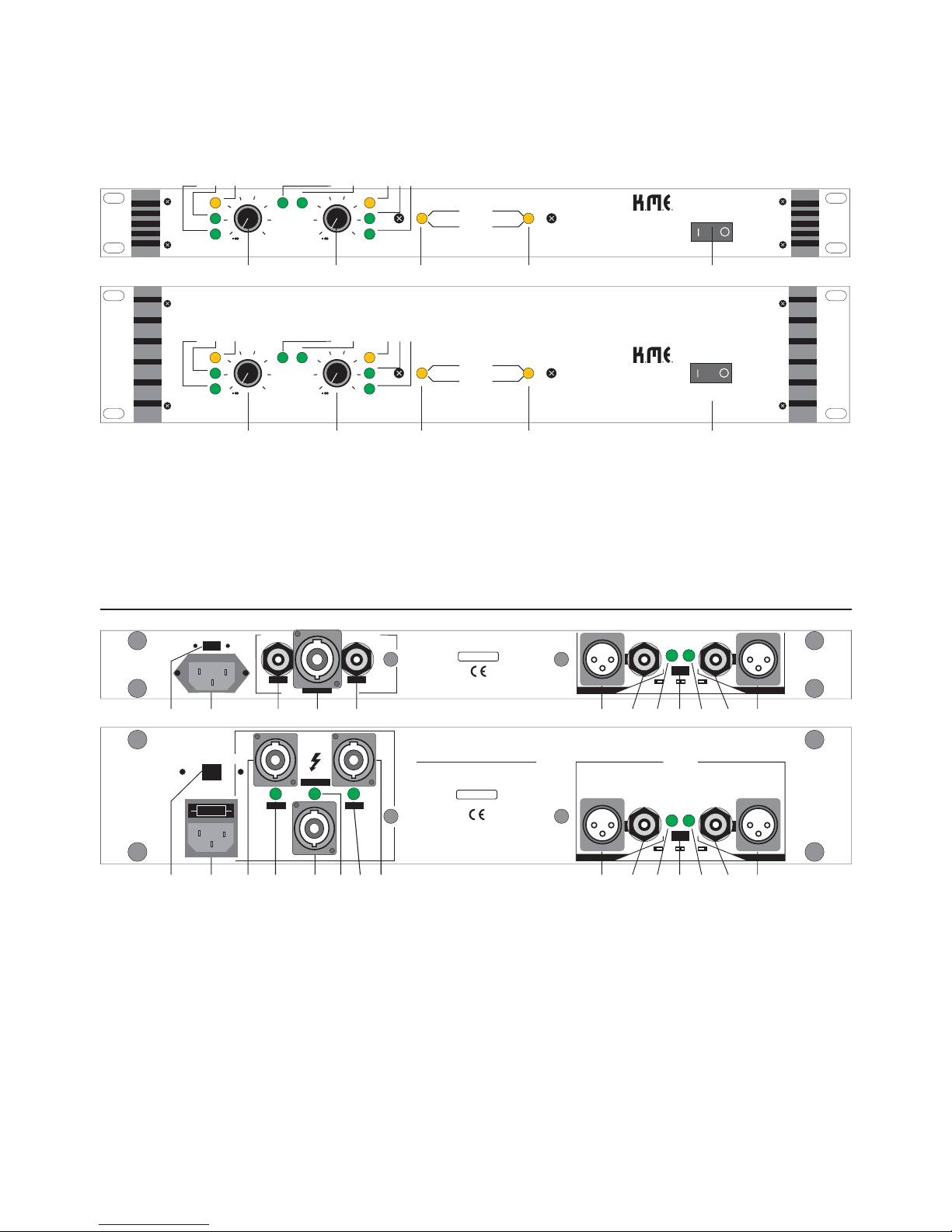
1. Ausgänge Kanal A, Kanal B und Brücke
Stereo- u. Mono- Betrieb:
Anschluß im Brückenmodus:
2. Eingänge Kanal A, Mono oder Brücke (27,28) und
Eingänge Kanal B (22,23)
Umschalter zwischen Stereo-, Mono- und Brücken-Modus (25)
3. Anschluß Netzkabel (15)
- kompakte 19 Zoll Endstufen
SPA 240 S: 1 HE mit 2 x 120 W Leistung
SPA 450 S: 2 HE mit 2 x 225 W Leistung
- geeignet für Stereo- und Mono-Betrieb
- Eingänge XLR und Klinke sind symmetrisch, können aber auch
unsymmetrisch angeschlossen werden (vgl. obiges Schema)
- ständig wirksames Subsonic-Filter verhindert unnötige
Belastungender angeschlossenen Boxen durch (unhörbare)
tieffrequente Signale
- pro Kanal unabhängig wirkende Limiter verhindern Verzerrungen
des Ausgangssignales bei Ansteuerung über Nennpegel.
- keine Einschaltgeräusche durch verzögerte Zuschaltung der
Ausgänge
- kurzschlußfeste Ausgänge gewährleisten in Verbindung mit der
pro Kanal separat wirkenden Thermoschutzschaltung der
Endstufe eine hohe Sicherheit gegen mögliche Fehlbedienung
- Gleichspannungsschutzschaltungen kontrollieren jeden
Endstufenausgang und schalten bei Auftreten von unzulässigen
Gleichspannungen die Lautsprecher ab.
- Im Brückenmodus ist beim Ansprechen einer Endstufenschutz-
schaltung ein weiterer Betrieb mit verminderter Leistung
möglich.
- Eine Einschaltstrombegrenzung verhindert problematische
Stromspitzen im Netz.
- einfachste Bedienung durch vielfältige unterstützende LED-
Anzeigen.
Die Betriebsart STEREO bzw. MONO wählen Sie mit Schalter (25).
Bei der SPA 450 S kennzeichnen die LED´s (17) und (20) die zu
belegenden Ausgänge. Verbinden Sie Ihre Lautsprecherboxen mit
den entsprechenden Ausgängen für Kanal A (21) bzw. Kanal B (16).
Für den Brückenbetrieb stellen Sie den Schalter (25) auf BRIDGE
(Mittelstellung). Bei der SPA 450 S zeigt die zugehörige LED (19) auf
den zu belegenden Brückenausgang (18). Der Anschluß der Box(en)
(mindestens 8 Ohm Impedanz!) erfolgt nun an diesem SPEAKON-
Ausgang (18).
Zur freien Auswahl stehen pro Kanal eine XLR- und eine Klinken-
buchse zur Verfügung. Beide sind gleichrangig und miteinander
direkt verbunden. Die Eingänge sind symmetrisch ausgelegt, ein
unsymmetrischer Anschluß ist ebenfalls bei entsprechender
Beschaltung möglich (vgl. oben).
Bei Schaltstellung BRIDGE und MONO sind nur die Eingangs-
buchsen des Kanales A (27,28) verwendbar. Dies wird durch die
LED (26) angezeigt. Boxenanschluß für den Brücken-Betrieb vgl.
Punkt 1! Im STEREO-Mode sind beide Eingangskanäle aktiv, ge-
kennzeichnet durch beide LED´s (24,26).
Schließen Sie die Endstufe SPA 240 S bzw. SPA 450 S mit dem
beiliegenden Netzkabel an eine vorschriftsmäßige Schutzkontakt-
steckdose an.
General Datas
Connection help
1. Outputs channel A, channel B and mono-bridge
Connection in Stereo- or Mono-mode:
Connection in bridge-mode:
Hint:
2. inputs channel A, mono or bridge (27,28) and
inputs channel B (22,23)
Switch between stereo-, mono- and bridge-mode (25)
- compact 19 " poweramps
SPA 240 S: 1 HU with 2 x 120 watts power
SPA 450 S: 2 HU with 2 x 225 watts power
- usable in stereo and mono
- inputs XLR and jack are symmetrical, you can use also in
a unsymmetrical manner (see pattern above)
- a permanent active subsonic-filter avoids unnecessary load
of the connected speaker cabinets by (inaudible)
low-frequency signals
- per channel independent working limiters prevent
distortions
of the output-signal by controlling about nominal level
- no turning-on-noises because the outputs are delayed
active
- the outputs are steady against short circuits and guarantie
together with the per each channel working thermo-
protection-circuit of the power-amps a high security against
user-mistakes
- in operation protection-circuits against direct-current
voltage
control each power-output and switch off the speakers in
case of inadmissible direct-current voltagesIn
- bridge-mode you can further use your amps with reduced
output-power in case of any protection-circuit is active !
- A limitation of the turning-on-current prevents problematic
current-impulses in mains.
- very simple use by many supporting LED´s
Please adjust the switch (25) to position STEREO or MONO.
On SPA 450 S the LED´s (17) and (20) show you the usable
outputs. Connect your speaker cabinets with the appropriate
SPEAKON-outputs for channel A (21) and channel B (16).
For bridge-mode please adjust the switch (25) to the
positionBRIDGE (middle position). On SPA 450 S the appropriate
LED (19) shows you the SPEAKON-bridge-output (18) for
connection of your box(es). The box(es) must have >= 8
Ohms impedance if you use the bridge-output (18).
You have for each channel one XLR- and one jack-socket.Both
(XLR , jack) are equal and directly connected.The inputs are
symmetrical, an unsymmetrical use is possible( see pattern
above ! ).
In position BRIDGE and MONO only the inputs of channel A
(27,28) can be used. The LED (26) gives you this information.
For connection of the speaker cabinets look to point 1. !In
STEREO-mode both inputs are active. This is shown by the both
Schema symmetrischer Anschluß/
pattern symmetrical connection
Schema unsymmetrischer Anschluß/
pattern unsymmetrical connection
21
3
21
3
GROUND
SIGNAL +
SIGNAL -
1 GROUND
2 SIGNAL +
3 SIGNAL -
+-+-
21
3
21
3
GROUND
SIGNAL +
1 GROUND
2 SIGNAL +
3 GROUND
+
+

Hinweis:
Bedienung
4. Schalten Sie die Endstufe SPA 240 S bzw. SPA 450 S
mit Schalter (5) ein.
5. Lautstärkeregler Kanal A (1) und Kanal B (2)
Mono- und Brücken- Betrieb:
6. LED-Anzeigen POWER ON/PROTECT
Kanal A (3) und Kanal B (4)
7. LED-Anzeigen INDICATOR Kanal A (13) und Kanal B (6)
8. LED-Anzeigen LIMIT Kanal A (11) und Kanal B (8)
9. Schalter zum Trennen Schaltungsmasse vom Gehäuse (14)
Der Gerätenetzanschluß der SPA 450 S enthält einen
herauszieh-bare Halterung für die Gerätesicherung. Bei einem Austausch
bitte nur elektrisch äquivalente Sicherung verwenden!
Im Stereo-Betrieb regeln Sie die Lautstärke des Kanales A mit (1) und die
des Kanales B mit (2), beide ACTIVE-LED´s (12,7) sind an.
Mit Regler (1) regeln Sie das Gesamtsignal im Brücken- und im Mono-
Modus. Angezeigt wird der Brücken-Mode mit LED (9), der Mono-Mode
mit LED (10), die ACTIVE-LED (12) für Regler (1) ist an.
(Umschaltung auf Brücke bzw. Mono mit Schalter (25), vgl. Punkt 2!)
Regler (2) ist im Brücken- bzw. Monobetrieb nicht aktiv!
Diese kombinierte Anzeige signalisiert bei grün den Betrieb des jeweiligen
Kanales. Treten die vorhandenen Schutzschaltungen in Funktion
(Einschaltverzögerung, Thermo- u. Lautsprecherschutz),so leuchtet die
Anzeige rot (PROTECT-Anzeige).
Diese beiden Anzeigen leuchten bei Anliegen von Eingangssignalen an
den Eingängen (22),(23) und (27),(28).Die Indikatorschwelle ist abhängig
von der Signalamplitude und der Stellung der Lautstärkeregler (1) u. (2).
Diese beiden LED´s signalisieren den Einsatz der internen Begrenzer.
Diese verhindern bei hohen Signalen unangenehme Verzerrungen,
schränken jedoch bei unkontrollierter Anwendung (überwiegendes
Leuchten von (8) bzw. (11)) den Dynamikbereich ihrer Anlage ein.
Der Betrieb der gesamten Verstärkeranlage sollte grundsätzlich nuran
einem gemeinsamen Netzstromkreis für alle Anlagenkomponenten
erfolgen, bei möglichst engem Zusammenliegen aller Anschlußstellen! Auf
diese Weise verringern Sie mögliche Beeinflussungen durch magnetische
Störfelder (Netztrafo,...) bei unsymmetrischen Signalleitungen zum
Verstärkereingang. Treten hoheBrummspannungen durch solche
Einflüsse auf, kann man mit demSchalter (14) in Stellung FREE diese
vermindern.
Die Normalstellung von (14) ist GROUND, ebenfalls bei symmetrischem
Betrieb.
Viel Spaß und Erfolg mit Ihrer
SPA 240 S bzw. SPA 450 S!
LED´s (24,26).
Connect the power amp SPA 240S/SPA450Swith the
enclosed power- cord to a correct power outlet.
The mains-connection (15) of the SPA 450 S contains a
fuse-bracket for taking out. Please take to change fuse only new
fuses with equal electrical properties!
In stereo-mode you can adjust volume for channel A with (1)and
for right channel with (2) both ACTIVE-LED´s are on.
With control (1) you can adjust the volume of main signal, the
ACTIVE-LED (12) is on. The bridge-mode is displayed by
LED (9), the mono-mode by LED (10).
(Switching to bridge- or mono- mode with switch (25) see
point 2!) The control (2) is not active in bridge-mode!
This combined display gives you by green color the infor-mation
about work of the appropriate channel. If the protection circuits
are active (delayed turn on, heat- and speaker protection),
theLED´s are shining in red color (PROTECT-display).
This both LED´s are shining if input-signals are available on the
inputs (22),(23) and (27),(28). The boundery condition of indi-
cator depends on the signal-amplitude and the position of the
volume-controls (1) and (2).
These both LED´s show´s you the work of internal limiters.
Theselimiters prevent during high signals unpleasant distortions,
butmake the dynamical range smaller ( in case of not controlled
use,permanent shining of (11) and/or (8) ).
To use PA-equipment you should take only one common mains-
circuit for all components of your equipment ! All mains-connec-
tions should be nearly situated!In this way you can decrease the
risk of influences by magneticfields (f.e. by transformers) in case
of unsymmetrical connectionto the inputs of the power amp. If
you have high buzzy-voltagesinfluenced by magnetic fieldes, so
you can decrease these byadjust switch (14) to position FREE.
Normally is the switch (14) in position GROUND, also in case of
symmetrical connection.
Connection to mains (15)
Hint:
Operation
4. Now turn the poweramp SPA 240S/SPA450Sonwith
switch (5).
5. Volume controls channel A (1) and channel B (2)
Mono- and Bridge-mode:
6. LED-displays POWER ON/PROTECT channel A (3)
and channel B (4)
7. INDICATOR-LED´s channel A (13) and channel B (6)
LIMIT-LED´s channel A (11) and channel B (8)
9. Switch FREE/GROUND (14)
Now please enjoy your
SPA240S/SPA450S!

Unsere SPA-S-Serie mit Konvektionskühlung verwirklicht höchste Ansprüche an Qualität, Zuverlässigkeit,
Kompaktheit und ein ausgezeichnetes Preis-Leistungs-Verhältnis. Insbesondere durch das eingesetzte Kühl-
System (ohne Lüfter+Geräusche) sind diese Endstufen sehr gut für Studios, Festinstallation bzw. für eine kleine
und mittlere Übungs-PA geeignet. Die Poweramps sind mit allen notwendigen sicherheitstechnischen
Parametern ausgestattet und bieten beste Dynamik und Bass-Festigkeit in bewährter Qualität aus dem Hause
K.M.E. Sie sind desweiteren umschaltbar zwischen Mono-, Brücken- und Stereo-Betriebsart. Diese K.M.E. -
SPA-Endstufen sind universell nutzbar, eine durchdachte Gestaltung der Bedien-, Anzeige- und
Anschlußelemente ermöglicht dem Musiker einen problemlosen Einsatz.
Technische Daten /
technical characteristics
Leistung / power
Brücke / bridge 8W
Frequ.umfang /
frequ.range(+/-1dB)
Klirrfaktor /
distortion factor (1kHz)
Geräuschspannungsabstand /
signal to noise ratio (A, RMS)
Eingangsempfindlichkeit /
input sensitivity
Eingangsimpedanz /
input impedance
Impulsleistung pro Kanal/
impulse power each ch.(10 ms)
Anstiegsgeschwindigkeit /
slew rate ( V/µs )
Übersprechdämpfung /
crosstalk
Dämpfungsfaktor /
damping factor ( 1 kHz )
Anzeigen / displays
Abmessungen / dimensions
(BxHxT) in mm
Bedienelemente, Schalter /
serving controls, switches
Gewicht / weight (kg)
>30
0 dBm
40 kW
2 x POWER ON/PROTECT
2 x INDICATOR/LIMIT /ACTIVE
>80dB
>250/4W
483x88x330
(19",2HE)
483x44x330
(19",1HE)
MONO/BRIDGE/STEREO
1 x POWER
2 x VOLUME
1 x GROUND/FREE
7,5 10,5
200 W
180 W
< 0,1 %
> 100 dB
20 - 20000 Hz
400 W
4W
8W
2 x 120 W
2 x 70 W
2 x 225 W
2 x 130 W
300 W
>83dB
konvektionsgekühlt
Input symmetrisch und
unsymmetrisch
beste Verarbeitung und
hohe Zuverlässigkeit
Limiterschaltung und
Brückenmode bei
SPA240S/SPA450S
linearer Frequenzgang
sehr gute Dynamik
hohe Bassfestigkeit
Speaker-Protection
Gleichstromschutz
Outputs kurzschlußfest
Einschaltverzögerung
SPA 240 S SPA 450 S
230V~AC;50-60 Hz
Netzspannung /
power requirements
MONO/BRIDGE


Klingenthaler Musikelektronik GmbH
Auerbacher Straße 268
08248 Klingenthal / Germany
phone +49 (0)37467 - 558-0
fax +49 (0)37467 - 558-33
www.kme-sound.com
Technischer Stand Februar 2005.
Der Inhalt entspricht dem Stand bei Drucklegung. Technische Änderungen, Druckfehler und Irrtümer vorbehalten.
Feb 2005 / SL
Technical State February 2005
The content corresponds to the state at printing. Subject to technical alterations. Misprints and errors expected.
Feb 2005 / SL
This manual suits for next models
1
Table of contents
Other K.M.E. Amplifier manuals