König & Meyer 80359 User manual

SICHERHEITSHINWEISE
Die Sicherheit der Installation hängt ab von:
ALLGEMEIN
Vor Gebrauch Sichtprüfung vornehmen:
beschädigte Bauteile dürfen nicht eingesetzt
werden - bzw. erst nach einer qualifizierten
Reparatur oder nach einem Austausch.
VIERKANTSOCKEL
Aufgrund der Schwere vorsichtig handhaben,
insbesondere nicht fallen lassen (Quetschgefahr).
MONTAGE
Auf feste Schraubverbindungen achten.
UNTERGRUND
Ständer nur auf geeigneten, d.h. ebenen und
tragfähigen Untergründen abstellen.
TRAGLAST
Nur für Sensorspender AUBYTEC® ATWS-2
UMGEBUNG
Negative äußere Einflüsse (Stöße, Herumzerren,
Erschütterungen, Wind, Nässe etc.) sind zu
vermeiden bzw. zu verhindern.
MONTAGEANLEITUNG
Bitte Sichtprüfung vornehmen, ob alle Teile vollständig
vorhanden und soweit erkennbar in Ordnung sind.
Ebenfalls die erforderlichen Schlüssel zurechtlegen.
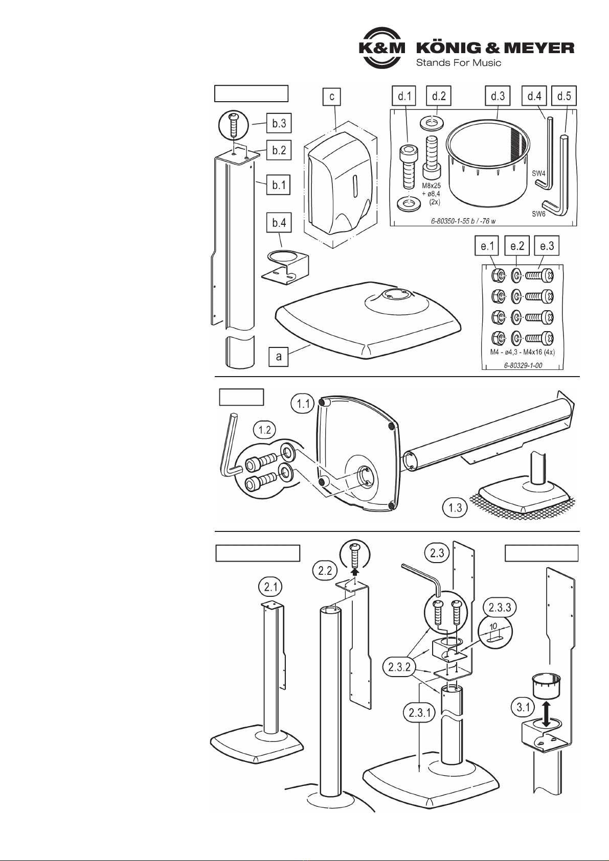
A. BESTANDTEILE
a.1 Vierkantsockel
b.1 Standsäule
b.1 Grundrohr
b.2 Spenderhalter
b.3 Linsenkopfschraube M6 x 25 mm (2x) - Schlüssel SW4
b.4 Tropfschalenhalter
c.1 Automatischer Spender (Sensorspender)
d.4 Zubehörbeutel
d.4 (6-80350-1-55 schwarz, 6-80350-1-76 weiß)
d.1 Zylinderschraube M8 x 25 mm (2x)
d.1 - Schlüssel SW6
d.2 U-Scheibe ø 8,4 mm (2x)
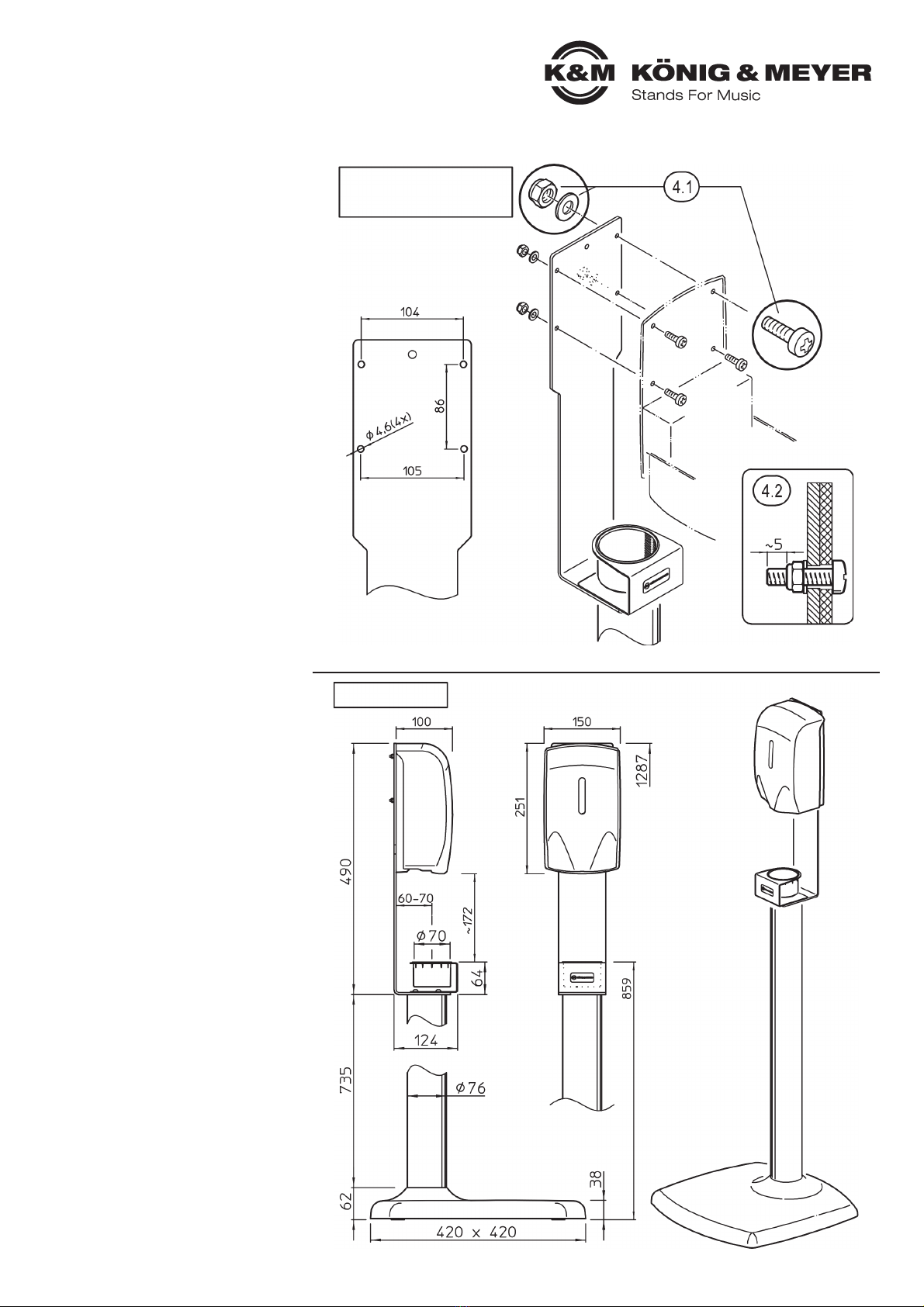
d.3 Tropfschale ø 70 mm
d.4 Inbusschlüssel SW4
d.5 Inbusschlüssel SW6
e.1 Zubehörbeutel (6-80329-1-00)
e.1 Sicherungsmuttern M4-DIN985 (4x)
e.1 - Schlüssel SW7 (nicht im Lieferumfang)
e.2 U-Scheibe ø 4,3 mm (4x)
e.3 Linsenkopfschraube M4 x 16 mm (4x)
e.3 - Kreuzschlitz Z2 (nicht im Lieferumfang)
B. STATIV
1.1 Vierkantsockel amit den Filzen auf den Boden
1.1 legen und anschließend senkrecht aufstellen.
1.2 Grundrohr b.1 mit Vierkantsockel averbinden.
1.2 Dazu die Schrauben M8 x 25 mm, SW6 d.1 sowie die
1.2 U-Scheiben ø 8,4 mm d.2 mit dem Schlüssel d.5
1.2 festziehen.
1.3 Vierkantsockel mit Grundrohr vorsichtig aufstellen.
C. SPENDERHALTER & TROPFSCHALE
2.1 Der Spenderhalter b.2 befindet sich zunächst
2.1 in platzsparender Transportstellung und muss
2.1 erst wie folgt umgebaut werden:
2.2 Spenderhalter vom Grundrohr b.1 trennen.
2.2 Dazu die Schraube b.3 komplett entfernen.
2.3 Spenderhalter nun korrekt positionieren:
2.3.1 Dabei ragt der kurze Schenkel des Spender-
2.3.1 halters ins Zentrum des Vierkantsockels.
2.3.2 Tropfschalenhalter b.4, Spenderhalter b.2 und
2.3.2 Grundrohr b.1 wieder verbinden mittels der
2.3.2 Linsenkopfschrauben M6 x 25 mm, SW4 b.3.
2.3.3 Der Abstand des Tropfschalenhalters kann um
2.3.3 bis zu 10 mm variiert werden (Langlöcher).
D. TROPFSCHALE
3.1 Die Tropfschale d.3 nun von oben in die
3.1 Aussparung des Spenderhalters b.4 einpressen.
3.1 Sie kann bei Bedarf (z.B. zur Reinigung) wieder
3.1 entnommen werden.
80359 Desinfektionsmittelsäule
80359 inklusive Sensorspender
Anzugsdrehmoment: max. 6 Nm
A. BESTANDTEILE
B. STATIV
C. SPENDERHALTER D. TROPFSCHALE
Diese Montageanleitung bitte sorgfältig durchlesen!

TECHNISCHE DATEN
F. ABMESSUNGEN
STATIV
- Höhe gesamt: 1287 mm
- Höhe Tropfschale: 859 mm
- Vierkantsockel: 420 x 420 x 38 mm
- Grundrohr: ø 76 x 735 mm
MATERIAL
- Sockel: Grauguss, Filz
- Grundrohr: Stahl
OBERFLÄCHE schwarz (-56), weiß (-66)
struktur pulverbeschichtet
GEWICHT 11,7 kg
SPENDERHALTER
- Haltewinkel: B x H x T - 120/92 x 400 x 120 mm
- Lochbild: 4x ø 4,6 mm - 104/105 x 86 mm
- Tropfschale: ø 70 x 47 mm
MATERIAL
- Haltewinkel: Stahl
- Tropfschale: Polyamid
OBERFLÄCHE schwarz (-56), weiß (-66)
struktur pulverbeschichtet
GEWICHT 1,8 kg
AUTOMATISCHER SPENDER
(SENSORSPENDER)
- Außenmaße: B x H x T - 150 x 100 x 251 mm
- Füllmenge: max. 1000 ml Desinfektionsmittel
- Detektionsbereich (Abstand bei Auslösung):
50 - 100 mm (± 20 mm)
- Betriebsart: Batteriebetrieb: 4x Baby/C-Zelle
(nicht im Lieferumfang enthalten)
Netzbetrieb: DC 6V
MATERIAL ABS/PP/PC
OBERFLÄCHE weiß
GEWICHT 0,8 kg
MONTAGEANLEITUNG
E. SPENDERHALTER und
E. AUTOMATISCHER SPENDER
Beachte beigefügte:
AUBYTEC®ATWS-2
Automatischer Spender Kurzanleitung
HINWEIS!
Für das vorliegende Stativ gilt zusätzlich:
4.1 Die Rückwand des Spenders ist...
4.1 ...mit geeigneten Schlüsseln...
4.1 ...unter Nutzung der vier Schraubensätze e.1, 2, 3
4.1 ...am Haltewinkel b(siehe 4 vorhandene Löcher)...
4.1 ...spielfrei zu befestigen
4.1 HINWEIS:
4.1 Die Schrauben sind fest,
4.1 aber nicht überfest anzuziehen
4.2 BEACHTE:
4.2 Sicherungsmuttern e.1 erfüllen
4.2 ihre Funktion nur, wenn die einge-
4.2 drehte Schraube e.3 einige mm
4.2 über die Mutter hinausragt.
INFORMATIONEN
HINWEIS: Beim Stativ und Automatischem Spender
HINWEIS: (Sensorspender) handelt es sich nicht um
HINWEIS: medizinisch zertifizierte Produkte.
- Negative Auswirkungen des Desinfektionsmittels
-auf das Produkt (Oberflächen, Material) sind uns
-nicht bekannt.
- Gleichwohl empfehlen wir, mögliche Rückstände
-des Desinfektionsmittels stets zu entfernen, um
-evtl. Schäden zu vermeiden und Sie so lange
-Freude am Produkt haben.
- Zur Reinigung ein leicht feuchtes Tuch und
-nicht scheuerndes Reinigungsmittel benutzen.
- Zur Reinigung des Spenders (Pumpeinheit) diesen
-mit Warmwasser und etwas Spülmittel durchspülen.
- Desinfektionsmittel ist nicht im Lieferumfang enthalten.
F. ABMESSUNGEN
E. SPENDERHALTER und
E. AUTOMATISCHER
E. SPENDER
KÖNIG & MEYER GmbH & Co. KG
Kiesweg 2, 97877 Wertheim, www.k-m.de
80359-000-56/66 Rev.11b 03-79-930-00 1/21
Lochbild für
Spendermontage

SAFETY INSTRUCTIONS
The safety of the stand depends on the:
GENERAL
Perform visual inspection before use:
Damaged components must not be used
- or only after a qualified repair or after
an exchange.
SQUARE BASE
Handle with care due to the heaviness, in particular,
do not drop (danger of crushing).
MOUNTING
Ensure that all screw connection are tight.
SURFACE
Only use the stand on suitable, i.e. level and
stable floors.
LOAD
Only for sensor dispenser AUBYTEC®ATWS-2
SURROUNDINGS
Negative external influences (knocks, dragging
around, vibrations, wind, wetness etc.) are to be
avoided or prevented.
INSTALLATION INSTRUCTIONS
Please carry out a visual check if all parts are
complete and as far as visible in order.
Provide the necessary keys.
A. COMPONENTS
a.1 Square base
b.1 Column
b.1 Base tube
b.2 Dispenser holder
b.3 Rounded head screw M6 x 25 mm (2x) - wrench SW4
b.4 Drip cup holder
c.1 Automatic dispenser (sensor dispenser)
d.4 Accessories bag
d.4 (6-80350-1-55 black, 6-80350-1-76 white)
d.1 Cylinder head screw M8 x 25 mm (2x)
d.1 - wrench SW6
d.2 Washer ø 8,4 mm (2x)
d.3 Drip cup ø 70 mm
d.4 Allen wrench SW4
d.5 Allen wrench SW6
e.1 Accessories bag (6-80329-1-00)
e.1 Lock nuts M4-DIN985 (4x)
e.1 - wrench SW7 (not included in delivery)
e.2 Washer ø 4,3 mm (4x)
e.3 Rounded head screw M5 x 16 mm (4x)
e.3 - Phillips screw Z2 (not included in delivery)
B. STAND
1.1 Place square base awith felts on the floor
1.1 and then set up vertically.
1.2 Connect the base tube b.1 to the square socket a.
1.2 Tighten the screws M8 x 25 mm, SW6 d.1 as well
1.2 as the washers ø 8.4 mm d.2 with the wrench d.5.
1.3 Carefully set up the square base with the base tube.
C. DISPENSER HOLDER
2.1 The dispenser holder b.2 is delivered in a
2.1 space-saving transport position and should
2.1 be rebuild as follows:
2.2 Separate the dispenser holder from the base tube b.1.
2.2 For this purpose, screw b.3 has to be completely
2.2 removed.
2.3 Now place the dispenser holder b.2 correctly:
2.3.1 Here the short leg of the dispenser holder protrudes
2.3.1 into the center of the square base.
2.3.2 Drip cup holder b.4, dispenser holder b.2 and
2.3.2 base tube b.1 are connected with the rounded
2.3.2 head screw M6 x 25 mm, SW4 b.3.
2.3.3 The distance of the drip cup holder can be varied by
2.3.3 by up to 10 (oblong holes).
D. DRIP CUP
3.1 Press the drip cup d.3 from above back into the
7opening of the holder b.4. For cleaning or other
7purposes, it can be removed again.
80359 Disinfectant column stand
80359 including sensor dispenser
Tightening torque: max. 6 Nm
A. COMPONENTS
B. STAND
C. DISPENSER HOLDER D. DRIP CUP
Please read these assembly instructions carefully!

TECHNICAL DATA
E. DIMENSIONS
STATIV
- Total height: 1287 mm
- Drip cup height: 859 mm
- Square base: 420 x 420 x 38 mm
- Base tube: ø 76 x 735 mm
MATERIAL
- Base: Grey cast iron, felt
- Base tube: Steel
SURFACE black (-56),white (-66)
structure powder-coated
WEIGHT 11.7 kg
DISINFECTANT HOLDER
- Mounting bracket: W x H x D - 120/92 x 400 x 120 mm
- Hole pattern: 4x ø 4,6 mm - W: 104 mm, H: 86 mm
- Drip cup: ø 70 x 47 mm
MATERIAL
- Mounting bracket: steel
- Drip cup: Polyamide
SURFACE black (-56),white (-66)
structure powder-coated
WEIGHT 1.8 kg
AUTOMATIC (SENSOR) DISPENSER
- Dimensions: W x H x D - 150 x 100 x 251 mm
- Filling volume: max. 1000 ml Disinfectant
- Detection range (distance at triggering):
50 - 100 mm (± 20 mm)
- Operating mode: Battery operation: 4x Baby/C-cell
(not included in delivery)
Mains operation: DC 6V
MATERIAL ABS/PP/PC
SURFACE white
WEIGHT 0.8 kg
INSTALLATION INSTRUCTIONS
E. DISPENSER HOLDER and
E. AUTOMATIC DISPENSER
See attached:
AUBYTEC®ATWS-2
Automatic Dispenser Quick Start Guide
NOTE!
For the present stand applies additionally:
4.1 The rear panel of the dispenser is...
4.1 ...with suitable keys...
4.1 ...using the four screw sets e.1, 2, 3
4.1 ...on the mounting bracket b(see 4 existing holes)...
4.1 ...fastened free of play
4.1 NOTE:
4.1 Tighten the screws firmly,
4.1 but not overtight
4.2 ATTENTIONS:
4.2 Lock nuts e.1 only fulfilled
4.2 their function if the screw e.3
4.2 protruded a few mm above the nut.
INFORMATION
NOTE: The stand and automatic dispenser (sensor
NOTE: dispenser) are not medically certified products.
- Negative effects of the disinfectant on the products
-(surfaces, material) are not known to us.
- Nevertheless, we recommend to always remove
-possible residues of the disinfectant in order to avoid
-possible damage and to enjoy the product as long as
-possible.
- For cleaning purposes use a slightly damp cloth and
-a non-abrasive cleaning agent.
- To clean the dispenser (pump unit), flush it with
-warm water and a little detergent.
- Disinfectant is not included in delivery.
F. DIMENSIONS
E. DISPENSER HOLDER
E. and AUTOMATIC
E. DISPENSER
KÖNIG & MEYER GmbH & Co. KG
Kiesweg 2, 97877 Wertheim, www.k-m.de
80359-000-56/66 Rev.11b 03-79-930-00 1/21
Hole pattern for
dispenser mounting
Table of contents
Languages:
Popular Accessories manuals by other brands

EVE
EVE door & window 20EAL9901 Get started

Johnson Controls
Johnson Controls NS8000 Series installation guide

E-TINT
E-TINT CTRL MG1 quick start guide

Toucan
Toucan TVD200WU user manual

ROSE DISPLAYS
ROSE DISPLAYS QUICKGRIP WITH CABLE CLIP AND LOOP AND... instruction sheet

GE Security
GE Security 868 Installation sheet