Kärcher WRH 1200 User manual

- 1
Please read and comply with
these original instructions prior
to the initial operation of your appliance and
store them for later use or subsequent own-
ers.
–All users: Users include trained auxilia-
ry personnel, operators and experts.
–Experts: Experts are individuals, who
are, according to their professional ed-
ucation, able to install the equipment
and to operate the same.
Tap water
Dirty water discharged from the high pres-
sure cleaner
Water prepared by the system for reuse in
the washing programmes (preliminary
washing, high pressure cleaning) with a
high-pressure cleaner.
Notes about the ingredients (REACH)
You will find current information about the
ingredients at:
www.kaercher.com/REACH
The warranty terms published by our com-
petent sales company are applicable in
each country. We will repair potential fail-
ures of your appliance within the warranty
period free of charge, provided that such
failure is caused by faulty material or de-
fects in fabrication. In the event of a warran-
ty claim please contact your dealer or the
nearest authorized Customer Service cent-
er. Please submit the proof of purchase.
Danger
Immediate danger that can cause severe
injury or even death.
몇Warning
Possible hazardous situation that could
lead to severe injury or even death.
Caution
Possible hazardous situation that could
lead to mild injury to persons or damage to
property.
The system cleans dirt water discharged
from vehicle cleaning and provides proc-
essed water to the high-pressure cleaner
(max. 1,200 litres per hour). The used wa-
ter can only be used for cleaning pro-
grammes (for e.g. preliminary washing,
high pressure cleaning). Processed water
is not suitable for use as rinsing water or for
applying drying aid or some other such pur-
pose.
Cleaning is done by:
–Separating heavy parts that easily set-
tle down in the gravel filter.
If the water level in the pump basin exceeds
a certain height, the solenoid valve opens
and water is routed to the sewer system via
the active carbon filter.
Pre-requisites for smooth functioning:
–Basin system according to the water
flow diagram shown in the "Function"
chapter.
–Maximum water quantity 2,000 l/h
–Minimum water quantity 1,200 l/h
–The wastewater in the system inlet con-
tains a max. of 30 mg of oil per litre of
water.
–The company supplied oil separator
must be properly maintained.
To avoid danger to persons, animals and
property before the first operation of the
system, read:
–this operating instructions manual, es-
pecially the safety instructions con-
tained therein
–the enclosed "Safety instructions for
waste water treatment plants"
–the respective national statutes of the
legislator
All individuals,who are involved, in the in-
stallation, the operation, the maintenance
and service of this equipment, must be
–have the requisite qualifications,
–know and observe the "Safety instruc-
tions for waste water treatment plants",
–know and have read this operations
manuals,
–know and follow the corresponding reg-
ulations.
The appliance may only be used by per-
sons who have been instructed in handling
the appliance or have proven qualification
and expertise in operating the appliance or
have been explicitly assigned the task of
handling the appliance.
This appliance is not intended for use by
persons with reduced physical, sensory or
mental capabilities.
The appliance must not be operated by
children or persons who have not been in-
structed accordingly.
Danger
Do not drink the processed water - health
hazard. The cleaned waste water is not of
a potable quality. It still contains some res-
idues of dirt and detergents.
Danger
Risk of injury on account of electric shock.
Ensure proper mains connection voltage
and the socket fuse.
Contents
About this Operations Manual EN . . 1
Environmental protection . . EN . . 1
Warranty . . . . . . . . . . . . . . . EN . . 1
Symbols in the operating in-
structions . . . . . . . . . . . . . . EN . . 1
Proper use . . . . . . . . . . . . . EN . . 1
Safety instructions . . . . . . . EN . . 1
Device elements . . . . . . . . . EN . . 2
Operation . . . . . . . . . . . . . . EN . . 2
Function . . . . . . . . . . . . . . . EN . . 3
Technical specifications . . . EN . . 3
Transport . . . . . . . . . . . . . . EN . . 3
Storing the device . . . . . . . . EN . . 3
Maintenance and care . . . . EN . . 4
Troubleshooting . . . . . . . . . EN . . 6
Accessories . . . . . . . . . . . . EN . . 7
EC Declaration of Conformity EN . . 7
Installing the unit (only for ex-
perts). . . . . . . . . . . . . . . . . . EN . . 7
About this Operations Manual
Target group for these instructions
Definitions
Fresh water
Waste water
Processed water
Environmental protection
The packaging materials are re-
cyclable. Please do not throw
packaging in the domestic
waste but pass it on for recy-
cling.
Old units contain valuable recy-
clable materials. Batteries, oil
and similar substances may not
be released into the environ-
ment. Therefore please dispose
of old units through suitable col-
lection systems.
Warranty
Symbols in the operating
instructions
Proper use
Safety instructions
General
10 EN

- 2
1 Tension lever
2 Unlocking lever
3 Filament filter
4 Multi-channel valve
5 Manometer at the filter inlet
6 Overflow valve
7 Throttle valve **)
8 Manometer active carbon filter
9 Active carbon filter
10 Hose coupling at output of active car-
bon filter
11 Hose coupling at input of active carbon
filter
12 Safety valve
13 Aperture
14 Filtrate hose
15 Switch solenoid
16 2. Active carbon filter **)
17 Test tap **)
18 Solenoid valve
A To the sludge collector
B to collect sludge (rinse back)
C from the immersion pump
D To the sludge collector (excessive pres-
sure)
E to the high-pressure cleaner / proc-
essed water tank (filling)
F To the drainage system
**) Option
Proceed as follows to subsequently change
the filter tension:
Turn the tension lever to the left until the
lever reaches the stop. Then attach it
with the unlocking lever.
Turn the lever of the multi-channel
valve in "FILTRATION" position.
Note
After longer idling times it takes a lot of ef-
fort to activate the multi-channel valve.
Check filter pre-tension.
Start the pump in the building.
Note
During normal operations, you must back-
wash the filter at least once daily. The sys-
tem does not release any processed water
during the back-rinsing process..
During backwash, the dirt collected in the
filament filter is removed. To do this, the fil-
ament filter is rinsed in the reverse direc-
tion. The rinsed dirt is routed to the sludge
collector of the recycling system.
Start the pump in the building.
몇Warning
The max. permissible flow volume during
return rinse is 2,000 l/h. Adjust flow volume
on throttle valve if necessary (order no.)
4.640-230.0).
Turn the lever of the multi-channel
valve in "RÜCKSPÜLEN/BACKWASH“
position.
Loosen the filament filter by turning the
tension lever in the anti-clockwise direc-
tion.
Wait for 30 seconds.
Tighten the filament filter and loosen it
immediately.
Repeat ten times this process of waiting
for 10 minutes - tightening - loosening.
Reset the filter pre-tension.
Turn the lever of the multi-channel
valve in "ERSTFILTRAT/RINSE“ posi-
tion.
Wait 2 minutes
Turn the lever of the multi-channel
valve in "FILTRATION" position.
If the high-pressure cleaner or the washing
system does not use up the water, the proc-
essed water is circulated to avoid foul
odour.
Note
The immersion pump can be periodically
switched on/off during non-operating hours
(for e.g. at night, over the week-end) to low-
er the operating hours. For this you can
connect the immersion pump via a timer to
the power supply.
Maximum interval increment: 1 hour.
The plant must be operated in frost-free
rooms. During frost, put the system out of
operation and remove all traces of water:
Pull out the hoses.
Let the system dry-run.
Switch off the building pump.
If there is risk of frosting, then any exist-
ing water traces must be removed (see
section "Anti-freezing").
Device elements
Operation
Adjust the filter pre-tension
Filter operations
Backwash
Processed water circulation
Frost protection
Shutdown
11EN

- 3
1 To the processed water tank/ high-
pressure cleaner
2 to drainage system *)
3 Control shaft *)
4 Immersion pump *)
5 Pump basin of the recycling system *)
6 Separation system (EN 858) *)
7 Sludge collection of the recycling sys-
tem *)
8 Circulation (to sludge collector)
9 Backwash pipe
10 Throttle valve
11 Safety valve
12 Manometer at the filter inlet
13 Multi-channel valve
14 Filament filter
15 Manometer active carbon filter
16 Active carbon filter
17 Test tap **)
18 2. Active carbon filter **)
19 Solenoid valve
20 Restrictor
21 Filtrate hose
22 Overflow valve
*) on building side
**) Option
The following section describes the flow-
path of the water in different positions of the
multi-channel valve.
In filter operations, the water flows via
–Immersion pump
–Multi-channel valve in "FILTRATION"
position
–Filter (flow direction of filtering)
–To the high-pressure cleaner/proc-
essed water tank
During backwash, the water flows via
–Immersion pump
–Multi-channel valve in position RÜCK-
SPÜLEN/BACKWASH"
–Filter (against flow direction of filtering)
–To the sludge collector
During final rinse the water flows via:
–Immersion pump
–Multi-channel valve in position ERST-
FILTRAT/RINSE
–Filter (flow direction of filtering)
–To the sludge collector
This position is not required for operating
the system.
If the water level in the pump basin exceeds
a certain height, the solenoid valve opens
and water is routed to the sewer system via
the active carbon filter.
–Suitable for dirt water
–Suitable for continuous operations
–With protection against dry-run
Note
Pumps with excessive performance can be
throttled via the throttle valve.
Caution
Risk of injury and damage! Observe the
weight of the appliance when you transport
it.
When transporting in vehicles, secure the
appliance according to the guidelines from
slipping and tipping over.
Caution
Risk of injury and damage! Note the weight
of the appliance in case of storage.
In der Anlage enthaltenes Restwasser
muss vor der Lagerung entfernt werden.
Store the appliance in a frost free area.
Function
Flow pattern
Functional description
FILTRATION
RÜCKSPÜLEN/BACKWASH
ERSTFILTRAT/RINSE
UMWÄLZUNG/RECIRCULATION
Function of active carbon filter
Technical specifications
Voltage V 230
Frequency Hz 50
Power W 12
Pressure (min.) MPa
(bar)
0,2 (2)
Pressure (max.) MPa
(bar)
0,35
(3,5)
Filter capacity l/h 1200
Waste water volume l/d 550
Content of active carbon
filter
l28
Width mm 1000
Depth mm 480
Height mm 1600
Weight kg 110
Immersion pump requirements
(building-side)
Pressure (min.) MPa
(bar)
0,2 (2)
Pressure (max.) MPa
(bar)
0,35
(3,5)
Minimum flow rate at 0.2
MPa (2 bar)
l/h 1200
Max. feed volume l/h 2000
Transport
Storing the device
12 EN

- 4
The bases of a safe operating of the equip-
ment is thr regularly maintenance accord-
ing to the following maintenance plan.
Use only original parts of the manufacturer
or part suggessted by him, such as
–parts and wearing parts,
–accessories parts,
–operating materials,
–cleaning agents.
Danger
Risk of accident while working on the unit.
During all tasks
First switch-on in voltage-less state, switch
off the emergency stop switch in the build-
ing and secure it against being switched on
again.
Shut off water supply.
Switch off the immersion pump in the
building.
–operator
Performances containing the notice
"operator" may only be performed by in-
structed individualls, who are able to
operate and service high pressure
equipment.
–Maintenance
Performances with the notice "mainte-
nance" may only be performed by the
Kärcher- Maintenance-Mechanics.
In order to guarantee a reliable operation
og the equipment, we success, you signed
Maintenance and care
Maintenance instructions
Who may perform maintenance?
Maintenance contract
Maintenance schedule
Time Activity Assembly af-
fected
Performance By whom
daily Backwash Filament filter Run bachwash Operator
weekly Clean the
filter
Drain at wash-
ing place
Clean the dirt collection basket in the floor. Operator
opinion Detergent con-
centration in proc-
essed water
Reduce the detergent dosing at the detergent dispenser if there is foam formation. Operator
Active carbon
filter
Set the switch of the solenoid to "1" with the submersion pump running. Nom-
inal value 25...30 l/h = 0.4...0.5 l/min. With lower flow, clean the shutter (see
"Clean shutter").
Operator
Set the switch of the solenoid to "1" with the submersion pump running. Take
water sample at the test tap and check for foaming (see "Testing the active
carbon filter").
If foaming is observed, replace the active carbon (see "Replace active carbon").
몇Warning
If the active carbon filter is not checked once a week, oil or tensid containing
water can be discharged into the sewer system. This can lead to consequenc-
es on the part of the authorities. In this case, there are no warranty claims ac-
cepted by KÄRCHER.
Operator
monthly opinion Sludge collec-
tion, pump ba-
sin
After sludge has been collected, there should be no sludge in any of the ba-
sins. The sludge in the sludge collector should be maximum 1 m in height.
Check sludge level; pump out and dispose off the sludge according to the local
regulations, if required.
Operator
opinion Float switch Check whether the float switch in the pump basin is freely movable. Operator
actuate Safety valve Unscrew the knurled screw of the safety valve with the submersion pump run-
ning - water will escape. (The knurled screw cannot be removed completely.
Screw in the knurled screw.
Operator
empty,
clean
Processed wa-
ter tank (if avail-
able)
Empty, clean, rinse and refill. Operator
Half-yearly
(if required)
Change
water,
clean the
basins
Sludge collec-
tion, oil separa-
tor, pump basin
Empty the basins, remove sludge completely and fill the basin with fresh wa-
ter. Store the waste disposal documents.
Operator/
Disposal
agency
annual Exchange
filter
Filter inlay Replace filter inlay of the filament filter. Operator/
Customer
Service
13EN

- 5
Mark the flow direction on the shutter.
Remove the shutter.
Clean the shutter opening with a needle
or a thin wire.
Install the shutter while observing the
flow direction.
Set the switch of the solenoid to "1" with
the submersion pump running and
check the flow.
Fill the glass bottle halfway with a water
sample after the active carbon filter and
close it.
Shake the glass bottle vigorously for
about 5 seconds.
If there is a closed foam cover, which has
not disintegrated after 40 seconds, the fill of
the active carbon filter must be replaced.
Foam picture filter OK: very thin foam ring
on the edge, which disintegrates quickly.
Foam picture filter exhausted: thick foam
ring on the edge, which does not disinte-
grate
Turn off the submersion pump.
Disconnect the hose coupling from the
input of active carbon filter
Disconnect the hose coupling from the
output of active carbon filter.
Unscrew the cap of the filter bottle.
Pour out the content of the bottle (2 per-
sons required) and remove the nozzle
pipe.
Rinse the filter bottle with water.
Insert the nozzle pipe.
Note
Dispose off the active carbon according to
local regulations.
Install the funnel 4.901-090.0 onto the
filter bottle.
Add 20 litres of water.
Add 10 kg of supportive gravel.
Add 14 kg = 28 l of active carbon.
Fill the filter bottle with water.
Attach and tighten the cap to the filter
bottle.
Connect the filter bottle output to the
hose from the manometer of the active
carbon filter.
Connect the Input of the filter bottle to
the hose from the flowmeter.
Turn on the submersion pump.
Set the solenoid switch to "1".
Rinse the filter bottle backwards until
the water escapes without bubbles.
Set the solenoid switch to "0".
Turn off the submersion pump.
Connect the filter bottle to the system
observing the correct flow direction.
Note
With systems with option 2. Exchange the
active carbon filter bottles so that the newly
filled filter bottle is the second one the liq-
uids flows through.
Turn on the submersion pump.
Check the flow, approximately 0,5 l/min,
clean shutter if necessary.
1 Nut
2 Tension lever
3 Screw of the tension lever bearing
4 Hose clip
5 Cover
6 Upper section
7 Filter inlay
8 Filtrate pipe
9 Threaded rod
10 Filament filter
11 Lower part
12 Lower console
13 Pin
Unlock filter.
Open the hose clamps.
Pull the hoses off the hose fittings.
Turn out both the screws of the tension
lever bearing.
Lift upward the entire tension lever
along with the bearings.
Unscrew the nuts at the upper end of
the threaded rods.
Remove the threaded rod assembly.
Pull out the filament filter towards the
front.
Remove the lid of the filament filter.
Pull out the lower part of the filament fil-
ter including filter inlay.
1 Grooved stone
Pullout the grooved stones between the
upper part and the filter inlay and be-
tween the lower part and the filter inlay.
Remove upper and lower part of filter
inlay.
Remove filtrate pipe from filtrate inlay,
Dispose of the filter inlay.
Attach filtrate pipe at one end of the
new filter inlay.
Tighten the filter inlay in such a way that
the filaments do not twist.
Push the fitrate pipe in the filter inlay
and by looking at the opposite side of
the filter element push the inlay in the
direction of the filtrate pipe.
Coat all rings with normal liquid soap
before carrying out any further installa-
tion tasks.
Note
Do not use silicon grease. Silicon in water
will hamper the cleaning and drying effect
during vehicle wash.
Insert the upper and lower part on the
filter element.
Align the upper and lower part in such a
way that the grooved stones can be in-
serted.
Insert the grooved stones and clamp it
tight by slightly turning the filter inlay.
Insert the lower part into the filament fil-
ter and push it in completely.
Replace the filament filter lid.
Clean the shutter
Check active carbon filter
Replace the active carbon
Replacing filter inlay
14 EN

- 6
Place the filament filter on the lower
console so that both the rear pins lock
into the long-holes of the console.
Align the lid, as shown above, and push
it in completely.
Push in the filament filter between the
two consoles.
Hook in the threaded rod assembly at
the lower console and insert the thread-
ed rods through the holes in the upper
console.
Fasten the threaded rods with undelay
washers and nuts.
Tighten the nuts in such a way that the
underlay washers can be still be moved
by hand.
Insert the hoses onto the hose fittings.
Tighten the hose clamps (keep the 35
mm distance).
Insert the tension lever with bearing
through the lid of the filament filter.
Turn the tightening lever in clockwise
direction. It should be possible to turn
the tightening lever in the range shown
above without exerting any pressure.
Otherwise, dismantle the tightening le-
ver and insert it again in the correct po-
sition.
Fasten the tension lever bearings with
screws.
Adjust the filter pre-tension.
Danger
Risk of accident while working on the unit.
During all tasks
Switch off the immersion pump in the
building.
–Operator
Work designated with the sign “Opera-
tor” may only be carried out by persons
who have been instructed in the safe
operation and maintenance on the
wash plant
–Customer Service
Work designated with the sign “Cus-
tomer Service” may only be done by the
fitters of Kärcher Customer Service or
fitters who have been authorised by
Kärcher.
Troubleshooting
Who may remedy faults?
Fault Possible cause Remedy By whom
Plant out of order Power supply to the pump in the building is
interrupted.
Check power supply and ensure proper supply. Operator
Processed water is
coloured or is foam-
ing too much
Filter pre-tension is not correct. Adjust the filter pre-tension Operator
Filter inlay is defective (leaky) Replacing filter inlay Operator, Cus-
tomer Service
Sludge collector or pump basin is dirty Emptying and cleaning the basins Operator/ Dis-
posal agency
Improper detergents are used in the wash-
ing hall
Use compatible detergents; rinse the system, if
necessary
Operator, Cus-
tomer Service
Cleaning dose is too high Check detergent dosing; reset, if necessary Operator, Cus-
tomer Service
Washing place cleaned with incompatible
detergents
Replace water and rinse the basins Operator
Filter output is too
low
Filament filter is blocked Backwash the filament filter; clean or replace filter
inlay if required.
Operator
Immersion pump is of lesser dimension Install a suitable immersion pump (see require-
ments under "Technical Data")
Operator
Immersion pump is blocked, defective Clean, repair, replace immersion pump Operator, Cus-
tomer Service
Pipe or valve is leaky, defective, blocked Check pipes and valves; clean, repair or replace as
required
Operator, Cus-
tomer Service
Filter is not clean fol-
lowing the backwash
Filter inlay is very dirty. Removing the filter inlay (see "Replacing the filter
inlay").
Dissolve 1 Tab of RM 760 in 5 litres of warm water.
Soak the filter inlay for 30 minutes and wash by
hand and squeeze afterwards.
Rinse the filter inlay with clear water.
If required, repeat the washing procedure.
Dispose of detergent.
Install a new filter inlay.
Operator
15EN

- 7
Order No. 5.033-239.0
Order No. 4.414-014.0
Order No. 4.901-090.0
Special funnel to fill in the active carbon fil-
ter filling
Order No. 2.641-831.0
Additional active carbon filter
Order No. 2.641-521.0
Manual switching between processed/
fresh water for using fresh water in the
high-pressure cleaner (for e.g. for rinsing).
Order No. 4.640-230.0
To throttle a raw water pump that is running
too high.
Order No. 2.641-510.0
Usage water ventilation to avoid bother-
some odours
Order No. 2.641-868.0
Second floater switch in the pump basin,
emits signal to external alarm setup, if the
pump basin is too full
Order No. 2.641-849.0
Support legs for filter module, if a wall
mounting is not possible
Order No. 6.474-073.0
Immersion pump as raw water pump
We hereby declare that the machine de-
scribed below complies with the relevant
basic safety and health requirements of the
EU Directives, both in its basic design and
construction as well as in the version put
into circulation by us. This declaration shall
cease to be valid if the machine is modified
without our prior approval.
The undersigned act on behalf and under
the power of attorney of the company man-
agement.
Authorised Documentation Representative
S. Reiser
Alfred Kärcher GmbH Co. KG
Alfred-Kärcher-Str. 28 - 40
71364 Winnenden (Germany)
Phone: +49 7195 14-0
Fax: +49 7195 14-2212
Winnenden, 2011/07/01
Notice
The equipment may only be installed by an
–mechanic of Kärcher
–or an from Kärcher authorized individual
The following requirements are necessary
in order to install the equipment:
–frost-free room with adequate ventila-
tion and exhausts
–sufficient lighting at the installation site
–Floor path for collecting sludge
–Strong wall for fastening the system
–The ground must be stabile and tight.
Unpack the equpiment and dispose of the
packing material properly.
The machine must have an FI fuse of type
B, 30 mA.
The electrical connection of the system
may only be performed by a qualified elec-
trician. Please follow the respective nation-
al regulations!
Electrical installation as per IEC 60364-1
The water installation depends on the spe-
cific conditions of the existing plant compo-
nents such as
–Type and model of high pressure cleaner
Note
The processed water outlet of the system is
directly connected to the water inlet of the
high-pressure cleaner. This can lead to
foam formation in the swimmer tank in
high-pressure cleaners with a swimmer
tank. In such a case, the high-pressure
cleaner must be switched to suction opera-
tioins (see separate operating instructions
of the high-pressure cleaner).
–Type and models of building-side com-
ponents (sludge collector, pump basin,
etc.)
–Nominal widtht, lengths and type of
channels
Hence, the water installation must be done
according to the specific local conditions.
The immersion pump specifications in the
building must meet the requirements out-
line in the "Technical Data / Immersion
Pump Requirements" section.
Danger
Risk of injury on account of tripping and fall-
ing.
Lay the hoses of the plant in such a way
that they do not pose a risk for tripping and
falling.
Note
During startup, set the multi-channel valve
to the position "BACKWASH" and rinse the
system until all bubbles have escaped from
the filament filter. After that, set the multi-
channel valve to "FILTRATION".
Accessories
Filter inlay
Filter fill active carbon filter
Funnel
Attachment kit active carbon filter
Attachment set 'Fresh water switching'
Attachment set input valve
Attachment kit ventilation
Attachment kit overflow
Attachment kit support leg
Immersion pump
EC Declaration of Conformity
Product: Effluent treatment plant
Type: 1.217-xxx
Relevant EU Directives
2006/95/EEC
2004/108/EC
Applied harmonized standards
EN 60204–1
EN 55014–1: 2006 + A1: 2009
EN 55014–2: 1997 + A2: 2008
EN 61000–3–2: 2006 + A2: 2009
EN 61000–3–3: 2008
EN 62233: 2008
Installing the unit
(only for experts)
Preparing the installation place
Unpack the equipment
CEO Head of Approbation
Electrical installation
Water installation
16 EN

- 1
Lire ces notice originale avant la
première utilisation de votre ap-
pareil, se comporter selon ce qu'elles re-
quièrent et les conserver pour une
utilisation ultérieure ou pour le propriétaire
futur.
–Tous utilisateurs : Les utilisateurs
sont les assistants, exploitants et spé-
cialistes expérimentés.
–Spécialistes : Les spécialistes sont les
personnes qui, de par leurs qualifica-
tions professionnelles, sont aptes à ins-
taller et mettre les installations en
service.
Eau du robinet
Eau sale sortant du nettoyeur haute pres-
sion
Eau traitée par l'installation, réutilisée pour
les processus de lavage (lavage prélimi-
naire, lavage haute pression) avec le net-
toyeur haute pression.
Instructions relatives aux ingrédients
(REACH)
Les informations actuelles relatives aux in-
grédients se trouvent sous :
www.kaercher.com/REACH
Dans chaque pays, les conditions de ga-
rantie en vigueur sont celles publiées par
notre société de distribution responsable.
Les éventuelles pannes sur l’appareil sont
réparées gratuitement dans le délai de va-
lidité de la garantie, dans la mesure où
celles-ci relèvent d'un défaut matériel ou
d'un vice de fabrication. En cas de recours
en garantie, adressez-vous à votre reven-
deur ou au service après-vente agréé le
plus proche munis de votre preuve d'achat.
Danger
Pour un danger immédiat qui peut avoir
pour conséquence la mort ou des bles-
sures corporelles graves.
몇Avertissement
Pour une situation potentiellement dange-
reuse qui peut avoir pour conséquence des
blessures corporelles graves ou la mort.
Attention
Pour une situation potentiellement dange-
reuse qui peut avoir pour conséquence des
blessures légères ou des dommages maté-
riels.
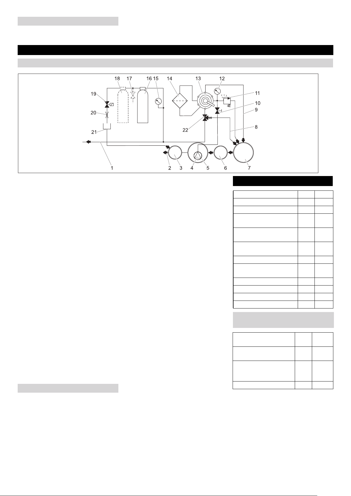
L'installation nettoie les eaux usées issues
du lavage du véhicule et met de l'eau
d'usage à disposition pour le nettoyeur
haute pression (max. 1200 litres à l'heure).
L'eau industrielle ne peut être utilisée que
pour des programmes de lavage (par ex.
lavage préliminaire, lavage haute pres-
sion). L'eau industrielle ne convient ni à
une utilisation en tant qu'eau de rinçage ni
à l'application d'auxiliaire de séchage, ni à
d'autres fins.
Le nettoyage s'effectue grâce à la :
–séparation de particules difficilement
enlevable dans le filtre à filaments.
Si le niveau d'eau dépasse une hauteur dé-
terminée dans le bassin de pompage,
l'électrovanne s'ouvre et de l'eau est ali-
mentée dans les canalisations via le filtre à
charbons actifs.
Les conditions préliminaires à un fonction-
nement irréprochable sont :
–un système de bassins conformément
au schéma de principe de l'eau au cha-
pitre «Fonction»
–Débit d'eau maximal 2000 l/h.
–Débit d'eau minimal 1200 l/h.
–Les eaux usées dans l'alimentation de
l'installation contiennent au maximum
30 mg d'huile par litre d'eau.
–Le séparateur d'huile monté par le
client doit être entretenu dans le res-
pect des préconisations.
Pour éviter certains dangers pour les per-
sonnes, les animaux et les objets, lisez
avant la première mise en service du por-
tique:
–le présent mode d'emploi et en particu-
lier les consignes de sécurité qu'il
contient
–les «consignes de sécurité pour les ins-
tallations de traitement d'eaux usées»,
ci-jointes
–les directives légales en vigueur dans le
pays d'exploitation
Toutes les personnes impliquées dans
l'installation, la mise en service, l'entretien,
la maintenance et l'exploitation de l'installa-
tion doivent
–disposer des qualifications requises,
–connaître et respecter les «consignes de
sécurité pour les installations de traitement
d'eaux usées»,
–connaître et respecter ce mode d'emploi,
–avoir connaissances et observer les direc-
tives qui s'appliquent.
L'appareil doit uniquement être utilisée par des
spécialistes qui sont instruits dans la ma-
noeuvre ou par des personnes qui peuvent jus-
tifiée leur aptitude d'utilisation et qui sont
explicitement mandatées pour l'utilisation.
Cet appareil n'est pas destiné à être utilisé
par des personnes avec des capacités phy-
siques, sensorielles ou mentales res-
treintes.
L’appareil ne doit jamais être utilisé par des
enfants ni par des personnes non avisées.
Danger
L'ingurgitation de l'eau d'usage peut nuire à
la santé. Les eaux usées purifiées n'ont
pas la qualité de l'eau potable. Elles
contiennent encore des résidus d'impure-
tés ainsi que des détergents.
Danger
Verletzungsgefahr durch elektrischen
Schlag. Alle berührbaren Metallteile sind in
den Potentialausgleich einzubeziehen.
Table des matières
A propos de ce mode d'emploi FR . . 1
Protection de l’environnement FR . . 1
Garantie . . . . . . . . . . . . . . . FR . . 1
Symboles utilisés dans le mode
d'emploi. . . . . . . . . . . . . . . . FR . . 1
Utilisation conforme . . . . . . FR . . 1
Consignes de sécurité . . . . FR . . 1
Éléments de l'appareil. . . . . FR . . 2
Utilisation . . . . . . . . . . . . . . FR . . 2
Fonction . . . . . . . . . . . . . . . FR . . 3
Caractéristiques techniques FR . . 3
Transport . . . . . . . . . . . . . . FR . . 3
Entreposage de l'appareil . . FR . . 3
Entretien et maintenance . . FR . . 4
Service de dépannage . . . . FR . . 7
Accessoires . . . . . . . . . . . . FR . . 8
Déclaration de conformité CE FR . . 8
Installation de l'appareil (Uni-
quement pour les spécialistes) FR . . 8
A propos de ce mode
d'emploi
Public cible de ce mode d'emploi
Définitions
Eau propre
Eaux usées
Eau d'usage
Protection de
l’environnement
Les matériaux constitutifs de
l'emballage sont recyclables.
Ne pas jeter les emballages
dans les ordures ménagères,
mais les rendre à un système de
recyclage.
Les appareils usés contiennent
des matériaux précieux recy-
clables lesquels doivent être
rendus à un système de recy-
clage. Des batteries, de l’huile
et d'autres substances sem-
blables ne doivent pas être tout
simplement jetées. Pour cette
raison, utiliser des systèmes
adéquats de collecte pour élimi-
ner les appareils usés.
Garantie
Symboles utilisés dans le
mode d'emploi
Utilisation conforme
Consignes de sécurité
Généralités
17FR

- 3
Выключить насос, установленный на
заводе-изготовителе.
Если существует опасность замороз-
ков, дополнительно необходимо уда-
лить оставшуюся воду (см. раздел
"Защита от морозов").
1Кбаку стехнической водой/высоко-
напорному моющему аппарату
2кканализации *)
3контрольный колодец *)
4Погружной насос *)
5резервуар насоса системы повторно-
го использования*)
6устройство осаждения (EN 858) *)
7шламоуловитель системы повторно-
го использования*)
8Циркуляция (для улавливания шла-
ма)
9Трубопровод обратной промывки
10 Дроссельный клапан
11 Предохранительный клапан
12 Манометр на входе фильтра
13 Многоходовой клапан
14 Филаментный фильтр
15 Фильтр из активированного угля ма-
нометра
16 Фильтр из
17 активированного угля
18 Кран для отбора проб **)
19 2. Фильтр из активированного угля **)
20 Магнитный клапан
21 Дроссель
22 Шланг для фильтрата
23 Перепускной клапан
*) заводская
**) Опция
Ниже будет показан путь прохождения
воды при различных положениях много-
ходового клапана.
Во время функционирования вода течет
через
–Погружной насос
–Многоходовый клапан вположении
«FILTRATION»
–Фильтр (направление течения филь-
трации)
–Кбаку стехнической водой/высоко-
напорному моющему аппарату
Во время процесса обратной промывки
вода течет через
–Погружной насос
–Многоходовой клапан вположении
«RUECKSPUELEN/BACKWASH»
–Фильтр (против направления тече-
ния фильтрации)
–Вшламоуловителе
Во время процесса дополнительной
промывки вода течет через
–Погружной насос
–многоходовой клапан вположении
"ERSTFILTRAT/RINSE»
–Фильтр (направление течения филь-
трации)
–Вшламоуловителе
Это положение при работе установки не
используется.
Если уровень воды врезервуаре насоса
превышает заданную высоту, следует
открыть магнитный клапан, чтобы вода
стекла вканализацию после прохожде-
ния через фильтр из активированного
угля.
–пригодно для грязной воды
–пригодно для длительного использо-
вания
–Сзащитой от работу всухую
Указание
Излишнюю мощность насосов можно
уменьшить путем регулировки дрос-
сельным клапаном.
Вывод из эксплуатации
Назначение
Поточная схема
Описание работы
FILTRATION
RUECKSPUELEN/BACKWASH
ERSTFILTRAT/RINSE
UMWAELZUNG/RECIRCULATION
Работа фильтра из активированного
угля
Технические данные
Напряжение В 230
Частота Гц 50
Параметры Вт 12
Давление (мин.) МПа
(бар)
0,2 (2)
Давление (макс.) МПа
(бар)
0,35
(3,5)
Производительность
фильтра
л/ч1200
Объем сточных вод l/d 550
Емкость фильтра из ак-
тивированного угля
л28
Ширина мм 1000
Глубина мм 480
высота мм 1600
Вес кг 110
Требования кпогружному насосу
(заводского исполнения)
Давление (мин.) МПа
(бар)
0,2 (2)
Давление (макс.) МПа
(бар)
0,35
(3,5)
Подача минимальная
при давлении 0,2 MПa
(2 бар)
л/ч1200
Максимальная подача л/ч2000
99RU

- 4
Внимание!
Опасность получения травм иповреж-
дений! При транспортировке следует
обратить внимание на вес устройс-
тва.
Перед транспортировкой следует уда-
лить остатки воды, имеющиеся вуст-
ройстве.
При перевозке аппарата втранспортных
средствах следует учитывать действую-
щие местные государственные нормы,
направленные на защиту от скольжения
иопрокидывания.
Внимание!
Опасность получения травм иповреж-
дений! При хранении следует обра-
тить внимание на вес устройства.
Перед хранением следует удалить ос-
татки воды, имеющиеся вустройстве.
Прибор следует хранить взащищенном
от мороза помещении.
Важным условием для надежной работы
установки является регулярное техни-
ческое обслуживание, согласно следую-
щему плану технического
обслуживания.
Используйте только следующие ориги-
нальные запасные части изготовителя
или части, рекомендованные им:
–запасные иизнашиваемые части,
–принадлежности,
–рабочие вещества,
–моющие средства.
Опасность
Опасность несчастных случаев при ра-
боте на установке. При всех работах
Отключите установку от электропи-
тания, выключив главный аварийный
выключатель установки изаблокиро-
вав его от повторного включения.
Перекройте подачу воды.
Остановить погружной насос за-
водского исполнения
–Эксплуатационник
Работы спометкой "Эксплуатацион-
ник" разрешается проводить только
проинструктированным лицам, спо-
собным безопасно управлять иоб-
служивать оборудование высокого
давления.
–Сервисная служба
Работы спометкой "Сервисная служ-
ба" разрешается проводить только
монтерам сервисной службы фирмы
“Kдrcher“.
Для обеспечения надежной эксплуата-
ции установки рекомендуется заключе-
ние договора отехническом
обслуживании. Обратитесь, пожалуйс-
та, врегиональную сервисную службу
фирмы “Kдrcher“
Транспортировка
Хранение прибора
Техническое обслуживание
иуход
Указания по техническому
обслуживанию
Кому разрешается проведение работ
по техническому обслуживанию?
Договор отехническом обслужива-
нии
100 RU

- 5
План технического обслуживания
Время Дейс-
твие
соответству-
ющий узел
Проведение работ Кем прово-
дится
ежеднев-
но
Обрат-
ная про-
мывка
Филаментный
фильтр
Провести процесс обратной промывки Эксплуата-
ционник
ежене-
дельно
очистить Сток на моеч-
ной площадке
Почистить корзину грязеуловителя встоке основания.Эксплуата-
ционник
прове-
рять
Концентрация
моющего
средства втех-
нической воде
При образовании пены уменьшить дозу чистящего средства.Эксплуата-
ционник
Фильтр из ак-
тивированного
угля
Переключатель магнитного клапана установить вположение „1“ при
включенном погружном насосе. Заданное значение 25 - 30 л/ч= 0,4 - 0,5
л/мин. При наличии незначительной протечки очистить диафрагму (см.
раздел „Очистка диафрагмы“).
Эксплуата-
ционник
Переключатель магнитного клапана перевести вположение „1“ при вклю-
ченном погружном насосе. Спомощью крана для отбора проб взять про-
бу воды ипроверить на пенообразование (см. раздел „Проверка фильтра
из активированного угля“).
При образовании пены заменить фильтр из активированного угля (см.
раздел "Замена фильтра из активированного угля").
몇Предупреждение
Если еженедельная проверка фильтра из активированного угля не про-
водится, то вканализацию может попасть вода, загрязненная маслом
или ПАВ. Это может привести ксерьезным последствиям. Вданном
случае гарантийные обязательства KÄRCHER не выполняются.
Эксплуата-
ционник
ежемесяч-
но
прове-
рять
Шламоулови-
тель, резерву-
ар насоса
Во всех резервуарах, находящихся за шламоуловителем, не должно на-
ходиться никакой грязи. Высота грязи вшламоуловителе не должна пре-
вышать 1 м. Проверить уровень грязи, вслучае необходимости откачать
иутилизировать ее всоответствии сместными положениями.
Эксплуата-
ционник
прове-
рять
Поплавковый
выключатель
Проверить легкость хода поплавкового выключателя врезервуаре насо-
са.
Эксплуата-
ционник
нажать Предохрани-
тельный кла-
пан
Для выпуска воды необходимо вывинтить винт снакатанной головкой из
предохранительного клапана при включенном погружном насосе. (Не от-
винчивать до конца винт снакатанной головкой.
Заново завинтить винт снакатанной головкой.
Эксплуата-
ционник
удалить
содержи-
мое, по-
чистить
Бак стехничес-
кой водой (ес-
ли имеется)
Удалить содержимое, почистить, прополоскать иснова заполнить.Эксплуата-
ционник
раз впол-
года (при
необходи-
мости)
Поме-
нять во-
ду,
почис-
тить ре-
зервуар
Шламоулови-
тель, жировой
сепаратор, ре-
зервуар насоса
Опорожнить резервуар, полностью удалить грязь инаполнить резервуар
чистой водой. Сохранять документы относительно утилизации отходов.
Эксплуата-
ционник /
утилизатор
отходов
раз вгод заменить Фильтроваль-
ная вставка
Заменить фильтровальную вставку филаментного фильтра.Эксплуата-
ционник /
сервисная
служба
101RU

- 6
Указать пропускное направление на
диафрагме.
Вынуть диафрагму.
Очистить отверстие диафрагмы спо-
мощью иголки или тонкой проволоки.
Установить диафрагму соблюдая
правильность расположения пропус
кного направления.
Переключатель магнитного клапана
установить вположение „1“ при
включенном погружном насосе ипро
верить расход.
Стеклянный резервуар наполовину
заполнить пробой воды после запол
нения фильтра из активированного
угля изакрыть резервуар.
Сильно встряхивать стеклянный
баллон на протяжении 5 секунд.
При образовании закрытых пенистых
покрышек, которые не распадаются вте-
чение 40 секунд, следует заменить со-
держимое фильтра из активированного
угля.
Нормальное пенообразование при ис-
пользовании фильтра: очень тонкое
кольцо пены по краям, которое быстро
распадается.
Пеногасительная способность фильтра
исчерпана: толстое кольцо пены по кра-
ям, которое не распадается.
Выключить погружнойнасос.
Отсоединить вход шлангового со-
единения фильтра из активирован
ного угля.
Отсоединить выход шлангового со-
единения фильтра из активирован
ного угля.
Отвинтить крышку резервуара филь-
тра.
Вытряхнуть содержимое резервуара
(необходимо участие 2 человек) и
снять трубу сраспылителем.
Промыть резервуар фильтра водой.
Установить трубу сраспылителем.
Указание
Утилизировать активированный уголь
всоответствии сместными предпи-
саниями
Установить воронку 4.901-090.0 вре-
зервуар фильтра.
Залить 20 литров воды.
Засыпать 10 кг опорного гравия.
Засыпать 14 кг = 28 лактивированно-
го угля.
Заполнить резервуар фильтра во-
дой.
Завинтить иустановить на место
крышку резервуара фильтра.
Соединить выход резервуара филь-
тра со шлангом фильтра из активи
рованного угля манометра.
Соединить выход резервуара филь-
тра со шлангом расходомера.
Выключите погружной насос.
Установить переключатель магнит-
ного клапана вположение "1".
Производить обратную промывку
резервуара фильтра до тех пор, пока
вода не начнет течь без пузырьков
воздуха.
Установить переключатель магнит-
ного клапана вположение "0".
Выключить погружнойнасос.
Резервуар фильтра подключается ксис-
теме сучетом направления потока.
Указание
Для установок сопцией 2. Заменить
резервуары фильтра из активирован-
ного угля для того, чтобы через зано-
во заполненный резервуар фильтра
протекало вдва раза больше жидкос-
ти.
Выключите погружной насос.
Проверить расход (прибл. 0,5 л/мин),
при необходимости очистить диа-
фрагму.
1Гайка
2Рукоятка зажима
3Винт опоры рукоятки зажима
4Хомут для крепления шланга
5Крышка
6Верхняя часть
7Фильтровальная вставка
8Труба для фильтрата
9Резьбовой шток
10 Филаментный фильтр
11 Нижняя часть
12 Нижняя консоль
13 Штифт
Освободить фильтр.
Открыть хомуты для крепления
шлангов.
Снять шланги сприсоединительных
патрубков.
Выкрутить оба винта опоры рычага
зажима.
Рычаг зажима вместе скреплением
вынуть вверх.
Открутить гайку на верхнем конце
резьбового штока.
Вынуть узел резьбового штока.
Вынуть вперед филаментный
фильтр.
Снять крышку филаментного филь-
тра.
Вынуть нижнюю часть фильтра вмес-
те сфильтровальной вставкой.
1Центрирующая шпонка
Вынуть центрирующие шпонки меж-
ду верхней частью ифильтроваль-
ной вставкой имежду нижней частью
ифильтровальной вставкой.
Снять сфильтровальной вставки
верхнюю инижнюю части.
Вынуть из фильтровальной вставки
трубу сфильтратом.
Утилизировать фильтровальную
вставку.
Насадить трубу для фильтрата на
один конец новой фильтровальной
вставки.
Зажать фильтровальную вставку та-
ким образом, чтобы филаментное
волокно не скручивалось.
Вдвинуть трубу для фильтрата в
фильтровальную вставку, регулируя
положение трубы для фильтрата и
глядя при этом на противоположную
сторону фильтрующего элемента.
Перед дальнейшей сборкой все О-
образные прокладки смазать обыч-
ным жидким мылом.
Очистка диафрагмы
Проверить фильтр из
активированного угля
Заменить активированный уголь
Заменить фильтроваль
нуювставку
102 RU

- 7
Указание
Не использовать консистентные смаз-
ки на основе силикона. Силикон, попав-
ший вводу, ухудшает результат
очистки ипросушки при мойке автомо-
билей.
Вставить вфильтрующий элемент
верхнюю инижнюю части.
Выровнять верхнюю инижнюю части
таким образом, чтобы можно было
вставить центрирующие шпонки.
Вставить центрирующие шпонки и
зажать их легким вращением филь-
тровальной вставки.
Вставить нижнюю часть вфиламент-
ный фильтр изадвинуть ее до упора.
Надеть крышку филаментного филь-
тра.
Установить филаментный фильтр в
нижнюю консоль таким образом, что-
бы оба нижних штифта попали в
длинные прорези консоли.
Выровнять крышку, как показано вы-
ше, иполностью вдвинуть.
Вдвинуть филаментный фильтр
между обеими консолями.
Узлы резьбовых штоков зацепить за
нижнюю консоль ивставить резьбо-
вые штоки через отверстия вверх-
ней консоли.
Закрепить резьбовые штоки спомо-
щью гаек иподкладных шайб.
Гайки затянуть только до такой сте-
пени, чтобы подкладные шайбы мож-
но было сдвинуть рукой.
Надеть шланг на присоединитель-
ный ниппель.
Затянуть хомуты для крепления
шлангов (держать на расстоянии 35
мм).
Вставит рычаг зажима вместе скреп-
лением через крышку филаментного
фильтра.
Повернуть рычаг по часовой стрелке.
Он должен провернуться на вышеу-
казанную отметку без применения
силы. Впротивном случае снять ры-
чаг зажима иснова вставить его в
правильном положении.
Закрепить опору рычага зажима спо-
мощью винтов.
Отрегулировать напряжение на
фильтре
103RU

- 8
Опасность
Опасность несчастных случаев при ра
боте на установке. При всех работах
Остановить погружной насос за
водского исполнения
–Эксплуатационник
Работы со ссылкой "Эксплуатирую-
щая сторона" могут проводиться
только определенными лицами, ко-
торые способны безопасно обслужи-
вать моющую установку.
–Сервисная служба
Работы со ссылкой "Сервисная служ-
ба" могут выпоняться только монте-
рами сервисной службы Kдrcher или
соответственно привлеченными
Kдrcher для этого монтерами.
Устранение неисправностей
Кто должен устаранять
неполадки?
Неполадка Возможная причина Способ устранения Кем прово-
дится
Установка вышла
из строя
Нарушена подача напряжения питания
на погружной насос заводского исполне-
ния
Проверить иобеспечить подачу электроэнер-
гии
Эксплуатаци-
онник
Техническая вода
изменила цвет и
сильно пенится
Неправильно установлено напряжение
на фильтре
Отрегулировать напряжение на фильтре Эксплуатаци-
онник
Неисправна фильтровальная вставка
(негерметична)
Заменить фильтровальную вставку.Эксплуатаци-
онник, сервис-
ная служба
Загрязнен шламоуловитель или резерву-
ар насоса
Опорожнить ипочистить резервуар Эксплуатаци-
онник / утили-
затор отходов
Впомещении мойки используются непод-
ходящие моющие средства
Использовать совместимые моющие средства,
вслучае необходимости прополоскать систему
Эксплуатаци-
онник, сервис-
ная служба
Дозировка чистящего средства слишком
высока
Проверить дозировку моющих средств, вслу-
чае необходимости настроить заново
Эксплуатаци-
онник, сервис-
ная служба
Очистка места мойки несовместимыми
моющими средствами
Сменить воду ипрополоскать резервуар Эксплуатаци-
онник
Производитель-
ность фильтра
слишком низкая
Забит филаментный фильтр Промыть филаментный фильтр, при необходи-
мости очистить или заменить фильтровальную
вставку.
Эксплуатаци-
онник
Погружной насос имеет меньшие разме-
ры
Использовать подходящий погружной насос
(требования приведены вразделе «Техничес-
кие характеристики»)
Эксплуатаци-
онник
Погружной насос засорен, поврежден Почистить, отремонтировать или заменить пог-
ружной насос
Эксплуатаци-
онник, сервис-
ная служба
Труба или клапан негерметичны, повреж-
дены, засорены
Проверитьтрубы иклапаны, вслучае необхо-
димости почистить, отремонтировать или заме-
нить
Эксплуатаци-
онник, сервис-
ная служба
Фильтр не очища-
ется после прове-
дения обратной
промывки.
Фильтровальная вставка сильно засори-
лась.
Снять фильтровальную вставку (см. раздел
„Замена фильтровальной вставки“).
Растворить 1 таблетку RM 760 в5 литрах теп-
лой воды.
Замочить фильтровальную вставку на 30 минут
вводе, затем промыть вручную ивыжать.
Промыть фильтровальную вставку чистой во-
дой.
Повторять промывку по мере необходимости.
Утилизировать моющее средство.
Установить патрон фильтра.
Эксплуатаци-
онник
104 RU

- 9
№для заказа: 5.033-239.0
Номер для заказа: 4.414-014.0
Номер для заказа: 4.901-090.0
Специальная воронка для засыпки на-
полнителя фильтра из активированного
угля
Номер для заказа: 2.641-831.0
Дополнительный фильтр из активиро-
ванного угля
Номер для заказа: 2.641-521.0
Ручной переключатель технической/чис-
той воды при использовании чистой
воды ввысоконапорном моющем аппа-
рате (например, полоскание).
Номер для заказа: 4.640-230.0
Для уменьшения числа оборотов слиш-
ком мощного насоса для подачи сырой
воды.
Номер для заказа: 2.641-510.0
Обдувка технической воды для защиты
от неприятного запаха
Номер для заказа: 2.641-868.0
Второй поплавковый выключатель вре-
зервуаре насоса подает сигнал на вне-
шнее сигнальное устройство вслучае
переполнения резервуара.
Номер для заказа: 2.641-849.0
Ножки для фильтровальных модулей,
на случай невозможности обеспечения
стенного монтажа
Номер для заказа: 6.474-073.0
Погружной насос вкачестве насоса для
подачи сырой воды
Настоящим мы заявляем, что нижеука-
занный прибор по своей концепции и
конструкции, атакже восуществленном
идопущенном нами кпродаже исполне-
нии отвечает соответствующим основ-
ным требованиям по безопасности и
здоровью согласно директивам ЕС. При
внесении изменений, не согласованных
снами, данное заявление теряет свою
силу.
Нижеподписавшиеся лица действуют по
поручению ипо доверенности руководс-
тва предприятия.
уполномоченный по документации:
S. Reiser
Alfred Kaercher GmbH & Co. KG
Alfred-Kaercher-Str. 28 - 40
71364 Winnenden (Germany)
Тел.: +49 7195 14-0
Факс: +49 7195 14-2212
Winnenden, 2011/05/01
Указание
Установку разрешается монтировать
только
–монтерам сервисной службы фир-
мы Kдrcher
–лицам, уполномоченным фирмой
Kдrcher
Для прявильной установки оборудова-
ния необходимо выполнение следую-
щих условий:
–Помещение, защищенное от мороза
сдостаточной вентиляцией
–достаточное освещение на месте
эксплуатации
–Сток основания кшламоуловителю
–Несущая стена для закрепления ус-
тановки
–Поверхность должна быть достаточ-
но прочной итвердой.
Распакуйте установку инаправьте упа-
ковочные материалы впереработку.
Прибор должен быть защищен спомо-
щью защитного переключателя FI, тип B,
30 мA.
Электрические соединения должны вы-
полняться только электриком. Следует
обязательно соблюдать национальные
требования!
электропроводка всоответствии сIEC
60364-1
Проведение воды зависит от особых ус-
ловий существующих компонентов уста-
новки таких , как
–Вид итип высоконапорных моющих
аппаратов
Указание
Отток технической воды из установки
напрямую связан сподачей воды ввы-
соконапорный моющий аппарат. Это
может вызвать образование пены в
баке споплавком, если используется
аппарат сбаком споплавком. Вэтом
случае аппарат должен быть установ-
лен на режим всасывания (см. отде-
льное руководство по эксплуатации
высоконапорного моющего аппарата).
–вид итип заводских компонентов
(шламоуловитель, резервуар насоса
ит.д.)
–Номинальный диаметр, длина и
конструкция каналов
На основании этого проведение воды
должно выполняться на месте по специ-
альным проектным документам.
Спецификация на погружной насос
должна соответствовать данным, приве-
денным вразделе «Технические харак-
теристики/Требования кпогружному
насосу».
Опасность
Опасность получения травмы от спо-
тыкания.
Шланги установки должны быть распо-
ложены так, чтобы такой опасности
не возникало.
Указание
При введении вэксплуатацию повер-
нуть многоходовой клапан вположение
„ОБРАТНАЯПРОМЫВКА/BACKWASH“и
промыть установку до полного удале-
ния воздушных пузырьков из филамен-
тного фильтра. Затем перевести
многоходовой клапан вположении
«FILTRATION».
Принадлежности
Фильтровальная вставка
Наполнитель фильтра из активиро-
ванного угля.
Воронка
Навесное оборудование, фильтр из
активированного угля
Съемный переключатель чистой
воды
Навесное оборудование, приемный
клапан
Навесное оборудование, вентиляция
Навесное оборудование, перелив
Навесное оборудование, ножка
Погружной насос
Заявление осоответствии
ЕС
Продукт Установка для переработ-
ки стоков
Тип:1.217-xxx
Основные директивы ЕС
2006/95/EC
2004/108/ÅÑ
Примененные гармонизированные
нормы
EN 60204–1
EN 55014–1: 2006 + A1: 2009
EN 55014–2: 1997 + A2: 2008
EN 61000–3–2: 2006 + A2: 2009
EN 61000–3–3: 2008
EN 62233: 2008
Монтаж установки (Только
для специалистов)
Подготовка места для установки
CEO Head of Approbation
Распаковка установки
Электропроводка
Водопровод
105RU
Other manuals for WRH 1200
1
Table of contents
Languages:
Other Kärcher Water System manuals
Popular Water System manuals by other brands

AmeriWater
AmeriWater V125DTH Operation & maintenance manual

AmeriWater
AmeriWater RAPID RESPONSE Operation & maintenance manual

Webasto
Webasto BLUE COOL Operation manual

Riello
Riello ALUDOMUS SOLAR KV/200 20 ISC SOLAR Installation and maintenance manual

Everpure
Everpure XC Filter Cartridge EV9613-09 Specification sheet

Enapter
Enapter WT 2.1 owner's manual