Küschall Mentor User manual

Mentor
Technical module


Technical module
1
Copyright © 08/2008,Küschall AG
K-Junior
K-Junior
Changing configurations
Table of contents
1 Adjustment possibilities 2
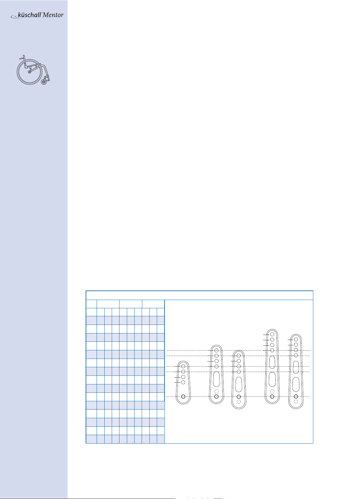
1.1 Seat width (SB) 2
1.2 Seat depth (ST) 2
1.3 Knee-to-heel length (UL) 2
1.4 Rear seat-to-floor height (SHh) 2
1.5 Front seat-to-floor height (SHv) 3
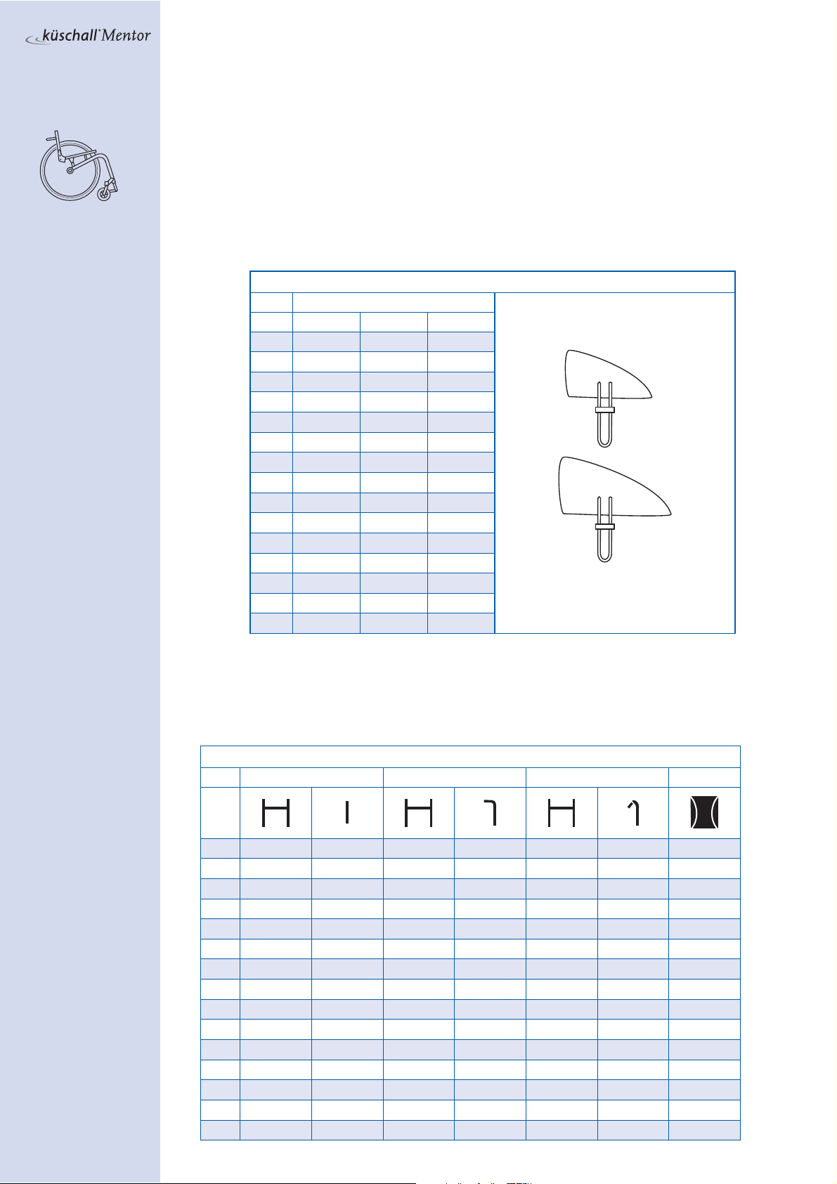
1.6 Siderest / Armrest 4
1.7 Clothes-guard / Mudguard 4
1.8 Backrest height 4
1.9 Backrest angle 5
2Assembly and adjustment methods 7
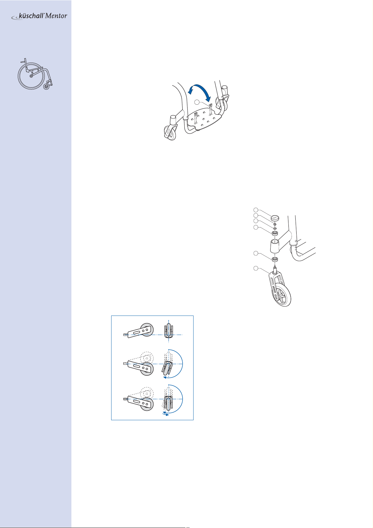
2.1 Footrest replacement 7
2.2 Footrest height adjustment 7
2.3 Footrest mounted in high position 7
2.4 Footplate angle adjustment 8
2.5 Front fork replacement 8
2.6 Quick release fork 9
2.7 Front wheel replacement 9
2.8 Rear seat height adjustment 10
2.9 Front seat height adjustment 10
2.10 Tipping point adjustment 11
2.11 Parking brakes assembly and adjustment 11
2.12 Clothes guard assembly or replacement 12
2.13 Mudguard assembly and adjustment 12
2.14 Armrest assembly and adjustment 13
2.15 Rear wheel extension assembly and adjustment 13
2.16 Rear wheel camber adjustment 14
2.17 Control of rear wheel parallelism 15
2.18 Backrest height adjustment 15
2.19 Backrest angle adjustment 17
2.20 Buggy push handle assembly 17
2.21 Antitipper assembly and adjustment 18
2.22 Active-Antitipper assembly and adjustment 19
2.23 Transit wheels assembly and adjustment 19
)DENTIFYINGANDREPAIRINGFAULTS

Technical module
2
Copyright © 08/2008,Küschall AG
K-Junior 1 Adjustment possibilities
1.1 Seat width (SB)
Available seat widths: SB24 to SB36, in 2 cm steps.
The seat width cannot be modified easily once it has been set. It would be necessary to
replace the seat module, backrest, rear wheel axle and footrest.
This modification is not described in the Mentor.
1.2 Seat depth (ST)
Available seat depths: ST25 to ST40 in 2.5 cm steps.
Adjusting the seat depth requires replacing the entire seat module including the seat
upholstery and seat rails as well as the seat cushion.
1.3 Knee-to-heel length (UL)
The footrest must be attached in a higher or lower position to adjust the leg length.
(Chapter 2.2)
The UL can be adjusted from 30cm to 41cm. For shorter knee-to-heel lengths a high-
mounted footrest must be fitted. (Chapter 2.3)
1.4 Rear seat-to-floor height (SHh)
To adjust the rear seat height, change the position of the seat module on the frame
(Chapter 2.8).The vertical seat brace is available in three sizes for seat heights of 33 cm
to 47 cm.
We generally recommend attaching the vertical seat brace on the lower hole to the
frame.
Rear seat height depending on rear wheel position and size
20‘‘ wheel 22‘‘ wheel 24‘‘ wheel
SHh S M L S M L S M L
33 1
34 2
35 3 5a 1
36 4 5 2
37 6 3 5a
38 7 9a 4 5 1
39 8962
40 10 7 9a 3 5a
41 11 8 9 4 5
42 12 10 6
43 12 11 7 9a
44 12 8 9
45 12 10
46 11
47 12
Please note:
Adjustments made
to the rear seat
height change the
seat angle.The
front seat height
may need to be ad-
justed accordingly.
1
2
3
45
6
7
89
10
11
12
5a
6a
7a
8a 9a
10a
11a
12a
SM L

Technical module
3
Copyright © 08/2008,Küschall AG
K-Junior
1.5 Front seat-to-floor height (SHv)
The front seat height depends on several factors that influence each other.
The dimension of the front and rear wheels determine the frame height.The position and
size of the hinge bracket to the seat module as well as the frame, seat depth and rear seat
height influence the front seat height.
1. Frame
The minimum front seat height depends on the combination of front wheels and rear
wheels:
Only choose combinations that are specified in the table above to ensure that the
frame is straight and the front wheel supporters are perpendicular to the ground.
2. Seat module
Once the rear and front wheels as well as the front forks have been defined, the front seat
height can be varied by adjusting the mounting position of the seat module on the frame.
There are 2 sizes of front hinge brackets each with 2 fastening possibilities to choose from:
(Chapter 2.9)
Possible combinations of front and rear wheels
SHv min. Rear wheel 3'' 4'' 5''
38 20‘‘ B A --
40 22‘‘ D C B
43 24‘‘ F E D
Please note:
Adjustments made
to the front seat
height change the
seat angle.The rear
seat height may
need to be adjusted
accordingly.
24''
22''
20''
3'' 4'' 5''
A B C D E F
1cm

Technical module
4
Copyright © 08/2008,Küschall AG
K-Junior 1.6 Siderest / Armrest
The standard clothes guard can be complemented with an armrest.
Mounting the armrest Chapter 2.14.
1.7 Clothes-guard / Mudguard
The standard clothes-guard can be replaced by a mudguard. (Chapter 2.12/2.13)
1.8 Backrest height
To adjust the backrest height, either adjust or replace the push handles or replace the
backrest tubes. (Chapter 2.18)
Clothes-guard / mudguard size
Rear wheel
M
L
SHh 20‘‘ 22‘‘ 24‘‘
33 L — —
34 L — —
35 M L —
36 M L —
37 M L —
38 M L —
39 M M L
40 M M L
41 M M L
42 M M L
43MMM
44 — M M
45 — M M
46 — — M
47 — — M
Backrest height depending on push handle and backrest tube
RH No push handles Standard push handles Foldable push handles Upholstery
27SSSSSSS
28.5 S S S S S S S
30SSSSSSS
31.5 S S S S S S M
33LSSSLSM
34.5 L M L S L S M
36LMLSLSM
37.5 L M L S L S L
39 L M L S L M L
40.5 L M L L L M L
42 L L L L L M L
43.5 L L L L L M L
45 L L L L L M L
46.5 L L L L L M L
48 L L L L L M L

Technical module
5
Copyright © 08/2008,Küschall AG
K-Junior
1.9 Backrest angle
To adjust the backrest angle re-position the eccentric plate in the backrest joint. (Chap-
ter 2.19)
The following angles can be set (in relation to the seat):
-8
0
+8
-4
+4
0
-8
0
+8
-4
+4
0
-8
0
+8
-4
+4
0
-8
0
+8
-4
+4
0
-8
0
+8
-4
+4
0
-8° -4° 0° +4° +8°

Technical module
6
Copyright © 08/2008,Küschall AG
K-Junior

Technical module
7
Copyright © 08/2008,Küschall AG
K-Junior
2 Assembly and adjustment methods
2.1 Footrest replacement
Remove the bolts on both sides.
Remove the footrest from the frame and insert
the new one.
Tighten the bolts securely on both sides.M
2.2 Footrest height adjustment
The footrest height can be adjusted in 1 cm
steps.
Remove the bolts from both sides of
footrest.
Slide the tube into the correct position,
replace the bolts on both sides of the
footrest and tighten.M.
The footrest must be firmly attached to the
frame tube.
A high-mounted footrest may be required if
the knee-to-heel length cannot be achieved
with the regular footrest.(Chapter 2.3)
2.3 Footrest mounted in high position
Slide the frame connector for the high-mounted footplate into the frame and
attach with bolt on both sides.M.
Fasten the clamp set with bolt to both sides of the frame, tighten slightly.
Slide the high-mounted footrest in the clamp set to the required height.
Tighten bolt .M
1
1
1
5
23
4

Technical module
8
Copyright © 08/2008,Küschall AG
K-Junior 2.4 Footplate angle adjustment
The footplate angle can only be adjusted if the footrest is angle adjustable. Proceed as
follows:
Loosen all four bolts until the footplate can be moved.
Pivot the footplate into the required position and tighten the bolts.M.
The footplate must be firmly secured to the wheelchair with no room for movement.
2.5 Front fork replacement
Remove the bearing block cap by
inserting two screwdrivers into the
grooves and pushing it upward.
Remove the nut and washer .
Remove the front fork .
Check the ball bearing blocks and
replace if necessary.
Attach the new front fork with the
washer and nut and tighten.
Functional check:
Tip the wheelchair 90° backwards, so that the
chair is lying on the backrest and rear wheels.
Turn the fork upwards (position A) and let it
tip downwards.
The fork is tightened correctly when it turns
slightly over the lowest point and stays there
(position B).
The fork hasn’t been tightened sufficiently if
it turns back into the lowest position (position
C). If tightened wrongly, there is a possibility
for the front wheels to start fluttering at high
speeds.
Replace the bearing block cap again.
1
1
2
3
4
5
4
A
B
C

Technical module
9
Copyright © 08/2008,Küschall AG
K-Junior
2.6 Quick release fork
The quick-release fork can only be used with the corresponding frame.To retrofit a wheel-
chair with a regular fork, the frame must be exchanged. In this case, please contact your
Küschall reference person.
Fork replacement
Press the pin on the bearing block and remove the fork.
Slide the new fork into the bearing block until the
mechanism locks into place and the fork can no longer be
removed.
2.7 Front wheel replacement
Remove the screws and washers and the front wheel axle .
Remove the front wheel .
Attach a new front wheel
or
Place the front wheel in its new position.
(2 bushings must be slid onto the axle with a Starec wheel, Skater wheel, 3’’ Sport
wheel or 5’’Softroll wheel.The bushings are already attached in the Smooth running
wheel, Sports wheel and Pneumatic wheel.)
Guide the front wheel axle through the fork, the bushing and the wheel , then
replace and tighten the screws .M.
Functional check: The wheel must be secured firmly, but still spin easily.
1
2
1
3
4
1
2
1
4

Technical module
10
Copyright © 08/2008,Küschall AG
K-Junior 2.8 Rear seat height adjustment
Remove the rear wheels and tip the wheelchair, so that it is positioned on its back.
Loosen the front hinge bracket bolt on both sides of the wheelchair.
If
the seat height is adjustable with the existing vertical seat brace , loosen bolt
and remove bolt and the horizontal seat brace .
If a new vertical seat brace is required, remove the existing one as well as the
horizontal seat brace and loosely attach the new vertical seat brace to the frame
with bolt .
Move the vertical seat brace along the rear hinge bracket so that the required holes
correspond.
Position the horizontal seat brace and fix it with the bolts .
Remount the rear wheels, turn the wheelchair over and verify the position of the
vertical seat brace . It should be as perpendicular to the ground as possible.
Tighten bolts .M.Mand .M
2.9 Front seat height adjustment
Remove the rear wheels and position the wheelchair on its back.
Loosen bolts and connecting the vertical seat brace to the seat module and
the frame respectively, on both sides of the wheelchair.
Replace the front hinge bracket or fasten it using the other hole to the front frame.
Remount the rear wheels, turn the wheelchair over and verify the position of the
vertical seat brace . It should be as perpendicular to the ground as possible.
Tighten bolts .Mand .Mon the vertical seat braces.
The seat angle is the
difference between
rear seat and front
seat height.
Please note:
Adjustments made to
the front seat height
changes the seat
angle.The rear seat
height may need to be
adjusted accordingly.
1
2
3
4
5
1
3
2
4

Technical module
11
Copyright © 08/2008,Küschall AG
K-Junior
2.10 Tipping point adjustment
The horizontal position of the seat module permits alterations of the tipping point.
Loosen bolts and .
Remove bolts and then slide the seat module either forwards or backwards
to the required position.
Reattach the seat module with bolts .Mand .Mthen tighten bolts .Mand .M.
By default, the front hinge brackets are attached to the middle position on the seat mod-
ule. The seat module can be set in 5 positions thanks to the 3 fixation possibilities in the
rear and the 5 in the front.
The vertical seat brace must be kept as perpendicular as possible after the adjustment.
2.11 Parking brakes assembly and adjustment
The parking brakes must be readjusted after any alterations or adjustments to the rear
wheels (e.g. camber adjustment).
Ensure sufficient air is in the tyres.
Loosen the hexagon socket bolt on the
brake holder.
Move the brake to the required position.
Tighten the hexagon socket bolt .Mon the
brake holder again.
The brake is adjusted correctly if the distance between
the wheel and the brake shoe is 25 mm when the brake is
disengaged. With the brake engaged, the brake shoe should not
sink more than 4 mm into the tyre.
The good function of
the arking brakes can
only be ensured if the
tires are sufficiently
inflated.
1
4
2
3
5
1

Technical module
12
Copyright © 08/2008,Küschall AG
K-Junior 2.12 Clothes guard assembly or replacement
The clothes guard fixation piece should be already fitted on the backrest tube.
Remove existing clothes guard by removing screw .
Align the clothes guard to the rear wheel. Locate the required position to fasten the
clothes guard to the fixation piece . Remove rear wheels
Fasten the clothes guard to the fixation piece with screw .M
If the seat module fixation piece needs to be replaced, remove the screw .
When unfolded, the tip of the clothes guard should be below the seat module and the
upper rim should run parallel to the rear wheel.
2.13 Mudguard assembly and adjustment
If replacing a clothes guard with a mudguard, first remove the clothes guard and the
bracket attached to the seat module.
Remove the rear wheels.
Attach the bracket .Mto the seat module and remount the rear wheels.
Slightly loosen the three screws on the adjustment plate and move it along the
mounting bracket until the mudguard is in position.
The position of the mudguard can also be altered by loosening the nuts .Mand .M
and adjusting the mudguard as required so that it runs parallel to the rear wheel.
Tighten the screws .M.
1
3
4
2
5
2
3
4
1

Technical module
13
Copyright © 08/2008,Küschall AG
K-Junior
2.14 Armrest assembly and adjustment
Fold the backrest onto the seat.
Remove the backrest bolt and replace with the armrest adapter on both sides.
Mount the connecting tube .M
To establish the correct armrest height, position the cylinder in the tube so that
the bolt .M can be fastened in the required hole. Insert the armrest into the socket.
2.15 Rear wheel extension assembly and adjustment
Unscrew bolts from both sides and remove the axle clamps together with the
axle.
Remove bolts and to dismantle the axle clamps.
Attach the axle clamping rings and screw with bolts to the required hole in
the rear wheel extension . Do not fully tighten the bolts . Be careful to make sure
that the screw , holding the 2 clamping ring halves, is accessible within the rear
wheel extension. Repeat for the other side.
The correct rear wheel extension and clamping ring must be used if a Vario-Ax is being
mounted.
Slide both rear wheel extensions onto the axle. Mount rear wheel extensions with
bolts .Mto the wheelchair frame.
Adjust rear wheel parallelism (chapter 2.17)
Tighten screw .Mto firmly secure axle. Fully tighten bolts .M
4
5
1
2
3
2
2
1
1
4
3
5
8
6
7
11

Technical module
14
Copyright © 08/2008,Küschall AG
K-Junior 2.16 Rear wheel camber adjustment
Assembly standard axle
A new axle has to be attached to adjust the rear wheel camber.
Remove bolts
and fold down the lower part of the axle clamp on both sides.
Replace axle
with a new axle with the correct camber.
Fold up the lower part of the axle clamp and insert bolt on both sides.
Adjust rear wheel parallelism. (chapter 2.17)
Tighten bolts
firmly.M.
Assembly Vario-Ax
Unscrew bolts and remove axle clamps together with the standard axle.
Mount the upper part of the Vario-Ax clamp with bolt .M
Mount the lower part of the Vario-Ax clamp with bolt .M Fit the Vario-Ax to the
clamps and loosely tighten the bolts .
Adjust rear wheel parallelism. (chapter 2.17)
Tighten bolts firmly.M.
Adjusting Vario-Ax
Loosen the blue knurled headed bolt on top of the Vario-Ax.
Pull out the wheel from the hub until the required camber is aligned.The
following positions are possible: 1, 3, 7 and 10 degrees.
Slightly tighten the blue knurled headed bolt until a resistance is felt (do not
force).
3
1
2
1
2
1
11
2
5
6
4
3
2
1

Technical module
15
Copyright © 08/2008,Küschall AG
K-Junior
2.17 Control of rear wheel parallelism
Loosen bolts on both clamps.Turn the axle, using the spirit level to adjust it to
the right position (the bubble must be centered in the spirit level).Tighten bolts
again.
Note: This adjustment must be carried out on a perfectly horizontal surface.The track
of the rear wheel is correct if (measured at height of hub) the distance between the rear
wheels is the same at the front and the back (x=y).
2.18 Backrest height adjustment
Adjustment of the push handles or telescopic tubes
A - Without push handles
Remove the backrest cover.
Locate the spring clips inside the backrest straps then press them into the tube.
Adjust the telescopic tube to the required height and let the spring clips snap into
the nearest holes.
Replace the backrest cover.
B - With push handles
Remove the backrest cover.
Slide the backrest strap either up or down to locate the fixing bolt . Remove nut
and bolt from both sides.
Adjust the push handle to the required height then fit the bolts into the nearest
holes and secure with the nuts.M.
Replace the backrest cover.
If the required height is not achieved, replace either the push handle, the telescopic
tube or the backrest tube.
1
2
2
B
A
1

Technical module
16
Copyright © 08/2008,Küschall AG
K-Junior
Replacement of backrest tube
Remove the backrest cover.
Slide the backrest strap either up or down to locate the fixing bolt . Remove nut
and bolt from both sides.
Remove the push handles and the upper adjustable backrest straps.
If the wheelchair is fitted without push handles, remove the telescopic tubes and the up-
per adjustable backrest straps by pressing the spring clips into the tube and then pulling
the tubes out of the backrest.
Remove the screws securing the backrest tube to the seat module.
Remove the lower adjustable backrest straps and the sleeve with the stop bolt
from the backrest tube .
Assemble the lower adjustable backrest straps and the sleeve with the stop bolt
to the new backrest tubethen secure the backrest tube to the seat module with
the screws .M
Replace the upper adjustable backrest straps and the push handles and secure with
the bolts and nuts.M.
If the wheelchair is fitted without push handles, replace the telescopic tubes and the up-
per adjustable backrest straps by pressing the spring clips into the tube and then sliding
the tubes to the required position until the spring clips snap into the nearest holes.
With the backrest in the upright position, check the adjustment
of the backrest stop screw .
The screw heads should only slightly touch the seat module
when the backrest clicks into its upright position. Adjust if
necessary by loosening the lock nut and moving the stop screw
either in or out as required.
Tighten the lock nuts.
Replace the backrest cover.
1
2
4
3
5

Technical module
17
Copyright © 08/2008,Küschall AG
K-Junior
2.19 Backrest angle adjustment
Fold the backrest onto the seat and loosen the lock nut of the stop bolt .Tighten
the stop bolt completely.
Remove the bolt of the eccentric plate . Remove the eccentric plate and reinsert
it in the required position.
Replace bolt
and tighten.M.
Unfold the backrest to the upright position until the spring pins engage in the
eccentric plate.Loosen the stop bolt until it slightly touches the frame and the
backrest joint no longer has any free movement.
Tighten the lock nuts.
Functional check: Unfold the backrest.The spring pins must lock into the holes in the
eccentric plate.
2.20 Buggy push handle assembly
Fasten the holder to the centre of the axle tube. Do not fully tighten the bolts .
Remove the QuickPin , loosen the clamp if necessary, then slide the buggy push
handle onto the holder and reinsert the QuickPin.
Turn the buggy push handle on the rear wheel axle to the desired position then
tighten the bolts .M.
Remove the buggy push handle from the holder.
Drill a hole through the axle using the centre hole of the holder as a guide. Secure
the holder to the axle with the bolt and nut .M
It is only possible to drill a hole through a standard axle. Do not drill al hole through a
Vario-Ax.
Verify that both eccen-
tric plates are in the
same position.
1
44
2
3
1
2
3
4
5
6
7

Technical module
18
Copyright © 08/2008,Küschall AG
K-Junior 2.21 Antitipper assembly and adjustment
Without rear wheel extension
Fold down the backrest and turn the wheelchair over. Remove the axle clamp bolts
then remove the lower part of the axle clamp .
Attach the adaptation lower clamp part with the axle bolts .M
Functional check: Adjust rear wheel parallelism. (chapter 2.17)
Fit the antitipper onto the adaptation clamp with the screws .MThe distance
between the ground and the antitipper wheels must measure 4-6 cm.The height of
the antitipper can be adjusted by pressing the spring pin and sliding the inner
part of the antitipper to the required position until the spring pin locates in the
correct hole.
Function control:The antitipper should swing under the chair without difficulty.
Antitipper assembly onto rear wheel extension
The adaptation holder must be attached either in the rear-most position,or between dou-
ble axles.
Fasten the adaptation holder with the spacer bushings to the rear wheel
extension using the bolts .
Fasten the antitipper to the adaptation holder with the bolts .MThe distance
between the ground and the antitipper wheels must measure 4-6 cm.The height of
the antitipper can be adjusted by pressing the spring pin and sliding the inner
part of the antitipper to the required position until the spring pin locates in the
correct hole.
Antitipper height adjustment
The height of the antitipper can be adjusted by pressing the spring pin and sliding
the inner part of the antitipper to the required position until the spring pin locates in
the correct hole.
Functional check: The antitipper should measure a distance of 4–6cm from the ground
and swing under the chair without difficulty.
1
1
2
3
1
1
3
4
5
1
2
3
4
5
6
7
1
Table of contents
Popular Control Unit manuals by other brands

DMP Electronics
DMP Electronics Wiegand 734N installation guide

ABB
ABB CP1484 manual

WEG
WEG DeviceNet CFW500 Installation, configuration and operations guide

Emerson
Emerson NEOTECHA SNB Series Installation and maintenance instructions

schroff
schroff 60714-050 user manual

Lenze
Lenze E94AYFLF Mounting instructions

Honeywell
Honeywell VR8305 Quick manual

KEBCO
KEBCO F5 COMBICOM ModBus instruction manual

Allmatic
Allmatic ARGO 1 Series manual

PEHA
PEHA PHC 940 AMA Installation and operating instructions

System Sensor
System Sensor 500 Series Installation and maintenance instructions

Metz Connect
Metz Connect MR-AO4 manual