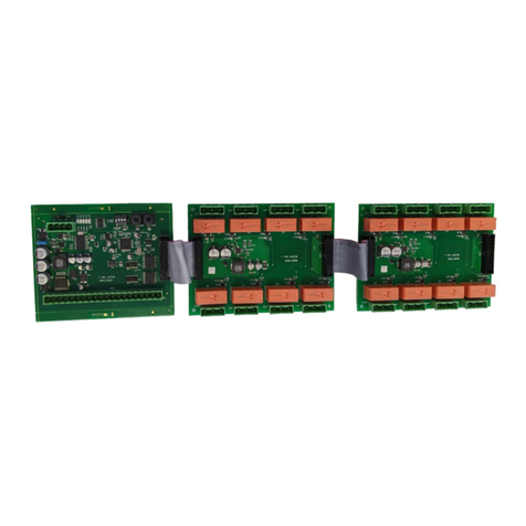
HID Aero X300 User manual

INSTALLATION GUIDE
Supplied parts
◾
HID Aero X300 Ouput Control Module (1)
◾
Installation guide (1)
◾
Mounting screws (4) 0.138" × 1" (3.5 mm × 25 mm)
Recommended parts
(not supplied)
◾
Certified DC power supply
◾
Drill with various bits for mounting hardware
◾
For DIN rail mounting: Brackets (2) - Phoenix Contact,
USA 10 Series Rail Adapter, part number 1201578.
Screws (4) - Self tapping, countersunk,
3.0 mm × 10 mm (or 3.0 mm × 8 mm)
X300 Overview
The X300 has 12 relays, five inputs and one RS-485 port for IO module connection.
POWER, TAMPER, AC FAIL, BATT FAIL
See step 6.
Status LEDs
See page 6
Status LEDs
See page 6
RELAYS 1-12
See step 4.
4.53"
(115 mm)
RELAYS 1-12
See step 4.
INPUTS 1-2
See step 3.
INPUTS 1-2
See step 3.
JUMPERS
See step 2.
5.51
"
(140 mm)
DIP SWITCH
See step 5.
IO MODULE PORT
See step 2.
CABLE REQUIREMENTS (NOT SUPPLIED)
IO Module
One twisted pair, shielded, 24 AWG, 120
impedance, 4,000 ft (1,200 m) maximum
Alarm Inputs
One twisted pair, 30
maximum
Relay Outputs
As required for the load
Power
2-conductor shielded
18 to 16 AWG, 500 ft (150 m)
Output Control Module
PLT-04236, Rev. A.3

HID Aero™ X300 Installation Guide
2
2. Communication wiring
Connect the X300 to the Aero X1100 intelligent
controller using IO Module ports (2-wire RS-485).
Use 1-twisted pair, shielded cable, 120
impedance,
24 AWG, 4,000 ft. (1,219 m) maximum.
Note: Both IN and OUT terminals on the IO MODULE
are the same port and are internally connected.
IO MODULE IN or IO MODULE OUT
Setting the termination jumpers
Install RS-485 termination jumpers on the interface
boards at each end of the communication bus only.
Failure to do so will compromise the proper operation
of the communication channel.
To other
devices
on the bus
To other
devices
on the bus
RS-485
termination jumper
JUMPER
DESCRIPTION
IN
Install only on the first and last unit on the
communication bus.
OUT
Install only if not the first or last unit on the
communication bus.
1. Mounting the X300
ATTENTION
Observe precautions for handling
ELECTROSTATIC SENSITIVE DEVICES
◾
Always mount the controllers and interface panels
in a secure area.
◾
Mount using the supplied screws 0.138" × 1"
(3.5 mm × 25 mm).
◾
Alternatively mount on a DIN rail using compatible
DIN rail mounting brackets and screws.
See Recommended parts.
Note: The side terminal connectors must be
removed to fit the mounting brackets.

HID Aero™ X300 Installation Guide
3.
Input circuit wiring
Inputs are typically used for the following:
◾
To monitor door position.
◾
Request to exit.
◾
Alarm contacts.
Input IN 1 and IN 2 circuits can be configured as
unsupervised or supervised and can use normally open or
normally closed contacts.
For a supervised circuit, add two 1K
, 1% resistors as
close to the sensor as possible.
Custom end of line (EOL) resistances may be configured
via the host software.
Note: The input circuit wiring configurations shown are
supported but may not be typical.
Unsupervised circuit IN 1 or IN 2
Supervised circuit IN 1 or IN 2
1K,1%
1K,1%
4.
Relay circuit wiring
Twelve relays are provided for controlling door lock
mechanisms or alarm signaling.
When controlling the delivery of power to the door
strike, the NO (Normally Open) and C (Common) poles
are typically used.
When momentarily removing power to unlock the door,
as with a mag lock, the NC (Normally Closed) and C
(Common) poles are typically used.
Check with local building codes for proper egress door
installation.
CAUTION
Door lock mechanisms can generate feedback to the
DC Strike
-
+
To DC power source
- +
Fuse
Diode
RELAY 1
to RELAY 12
relay circuit. This can cause damage and premature
failure of the relay, effecting the operation of the X300.
Use a diode to protect the relay. Use a wire of sufficient
gauge to avoid voltage loss.
Diode selection:
◾
Diode current rating: 1x strike current.
◾
Diode breakdown voltage: 4x strike voltage.
◾
For 12 V DC or 24 V DC strike, diode 1N4002
(100V/1A) typical.

HID Aero™ X300 Installation Guide
4
5.
DIP switch configuration
Switches
1
through 5 select the device address. Switches 6 and 7 select the communication baud rate.
Switch 8 is not in use.
1
2
3
4
5
6
7
8
SELECTION
OFF
OFF
OFF
OFF
OFF
Address 0
ON
OFF
OFF
OFF
OFF
Address 1
OFF
ON
OFF
OFF
OFF
Address 2
ON
ON
OFF
OFF
OFF
Address 3
OFF
OFF
ON
OFF
OFF
Address 4
ON
OFF
ON
OFF
OFF
Address 5
OFF
ON
ON
OFF
OFF
Address 6
ON
ON
ON
OFF
OFF
Address 7
OFF
OFF
OFF
ON
OFF
Address 8
ON
OFF
OFF
ON
OFF
Address 9
OFF
ON
OFF
ON
OFF
Address 10
ON
ON
OFF
ON
OFF
Address 11
OFF
OFF
ON
ON
OFF
Address 12
ON
OFF
ON
ON
OFF
Address 13
OFF
ON
ON
ON
OFF
Address 14
ON
ON
ON
ON
OFF
Address 15
OFF
OFF
OFF
OFF
ON
Address 16
ON
OFF
OFF
OFF
ON
Address 17
OFF
ON
OFF
OFF
ON
Address 18
ON
ON
OFF
OFF
ON
Address 19
OFF
OFF
ON
OFF
ON
Address 20
ON
OFF
ON
OFF
ON
Address 21
OFF
ON
ON
OFF
ON
Address 22
ON
ON
ON
OFF
ON
Address 23
OFF
OFF
OFF
ON
ON
Address 24
ON
OFF
OFF
ON
ON
Address 25
OFF
ON
OFF
ON
ON
Address 26
ON
ON
OFF
ON
ON
Address 27
OFF
OFF
ON
ON
ON
Address 28
ON
OFF
ON
ON
ON
Address 29
OFF
ON
ON
ON
ON
Address 30
ON
ON
ON
ON
ON
Address 31
OFF
OFF
115,200 BPS
ON
ON
38,400 BPS
OFF
ON
19,200 BPS
ON
OFF
9,600 BPS

HID Aero™ X300 Installation Guide
6. Input power, cabinet tamper, and UPS fault input wiring
The X300 requires 12-24 V DC power. Connect power
with minimum of 18 AWG wire.
Connect power ground to earth ground in only ONE
LOCATION within the system. Multiple earth ground
connections may cause ground loop problems and is
not advised.
Observe POLARITY on 12-24 V DC input.
Connect the AC FAIL and BATT FAIL inputs to the
corresponding contacts provided on the power supply.
Connect the TAMPER input to a tamper switch on the
enclosure.
TAMPER, AC FAIL, and BATT FAIL connections are
identical to inputs IN 1 to IN 2 and can be configured
as unsupervised or supervised. See step 3. Input
circuit wiring.

HID Aero™ X300 Installation Guide
6
Status LEDs
LED
POWER
ON SELF-TEST
NORMAL OPERATION
ONLINE
ON then OFF
Heartbeat and Online status. Offline = 1 sec rate, 20% ON. Online encrypted comm .1 sec
ON, .1 sec OFF, .1 sec ON, .1 sec OFF, .1 sec ON, .1 sec OFF, .1 sec ON, .3 sec OFF. Waiting
for application download
.1
sec ON,
.1
sec OFF.
COMM
ON then OFF
RS-485 comm status. Indicates communication activity on the SIO communication port.
BATT FAIL
ON then OFF
OFF = Inactive, ON = Active, Flash = Fault.*
AC FAIL
ON then OFF
OFF = Inactive, ON = Active, Flash = Fault.*
TAMPER
ON then OFF
OFF = Inactive, ON = Active, Flash = Fault.*
RELAY 1
OFF
ON = Energized
RELAY 2
OFF
ON = Energized
RELAY 3
OFF
ON = Energized
RELAY 4
OFF
ON = Energized
RELAY 5
OFF
ON = Energized
RELAY 6
OFF
ON = Energized
RELAY 7
OFF
ON = Energized
RELAY 8
OFF
ON = Energized
RELAY 9
OFF
ON = Energized
RELAY 10
OFF
ON = Energized
RELAY 11
OFF
ON = Energized
RELAY 12
OFF
ON = Energized
IN 1
ON then OFF
OFF = Inactive, ON = Active, Flash = Fault.*
IN 2
ON then OFF
OFF = Inactive, ON = Active, Flash = Fault.*
*If this input is defined, every three seconds the LED is pulsed to its opposite state for 0.1 seconds, otherwise,
the LED is OFF.

HID Aero™ X300 Installation Guide
Specifications
HID AERO X300
Input Voltage
12 to 24 V DC ± 10%
Maximum Input Current
500 mA
IO Module
2-wire RS-485, 2,400 to 115,200 bps, asynchronous,
half-duplex, 1 start bit, 8 data bits, and 1 stop bit
Inputs
Five unsupervised/supervised, standard EOL: 1k/1k
, 1%, ¼ watt
(Includes TAMPER, AC FAIL, and BATT FAIL inputs)
UL evaluation for access control use only
Output Relays
Twelve Form-C relays. Contact rating: 2 A @ 30 V DC resistive
ENVIRONMENTAL
Operating Temperature
32 to 158°F (0 to +70°C)
Storage Temperature
-67 to 185°F (-55 to +85°C)
Humidity
5 to 85% RHNC
MECHANICAL
Dimension
6.46" × 5.51" × 1.02" (164 mm × 140 mm × 26 mm)
Weight
342 g
These specifications are subject to change without notice.
Other HID Control Unit manuals
Popular Control Unit manuals by other brands
SMC Networks
SMC Networks SYA3000 Original instructions

Wave2wave
Wave2wave Rome500 Hardware installation manual

KWC
KWC F3SV1001 Installation and operating instructions
Kalatec Automacao
Kalatec Automacao 2DM860H Driver manual
RF-Star
RF-Star CC26X2R manual
Rodix
Rodix FEEDER CUBE FC-40 Plus Series Adjustments and Set Up

HP invent
HP invent ProCurve 8108fl Product End-of-Life Disassembly Instructions

GF
GF 567 instruction manual
Siemens
Siemens CM 1243-5 operating instructions
Watts
Watts LFM127-11 Installation, operation and maintenance
Rockwell Automation
Rockwell Automation Allen-Bradley 1441-DYN25-MBAL user manual
FULTON
FULTON ProtoNode FPC-N54 Startup guide
