K-Tech ET401A User manual

K-Phone ET401
Emergency Speakerphone
Instruction Book
Sentry(ET401A)
Fortress (ET1401A)
Commander (ET401A-OEM)
Liberator (ET401A-LP)
Please read carefully before
installation and operation

Page 2

Page 3
Table of Contents
Introduction
................................................................................... 4
Pre-Installation Checklist
.............................................................. 5
Wiring
........................................................................................... 5
Telephone Lines
........................................................................... 5
Telephone Line Specifications
....................................................... 5
Wiring Diagram
............................................................................. 6
Installation
.................................................................................... 7
Sentry (ET401A)
........................................................................... 7
Liberator (ET401A-LP)
.................................................................. 8
Fortress (ET1401A)
...................................................................... 9
Commander (ET401A-OEM)
....................................................... 10
Settings
...................................................................................... 11
Programming
.............................................................................. 12
Operation and
Testing................................................................. 16
Troubleshooting
.......................................................................... 17
Specifications
.............................................................................. 18
Code Compliance
....................................................................... 19
FCC Notice for Part 68
................................................................ 20
FCC Notice for Part 15
................................................................ 21
IC Notice
..................................................................................... 22
Service & Warranty Agreement
................................................... 23
For Technical Support call
1-800-993-9399 or (860) 489-9399

Page 4
Introduction
Thank you for purchasing the K-Tech K-Phone ET401 Emergency
Speakerphone. This vandal resistant speakerphone is designed to
provide reliable communication in the event of an emergency. Each
unit features a tone dialer capable of dialing five twenty-digit
numbers, a voice activated location announcer with 10 second
message, and remote, on-site, and off-site programming
capabilities. All programming features are stored in non-volatile
memory.
The K-Phone ET401 activates with a single press of the push-
button, which initiates automatic dialing of the programmed
emergency telephone number(s) until a called party answers. The
voice activated Voice Announcement replays the recorded
message, after which two-way communication begins or the
message can be replayed. The visual indicator illuminates to
indicate the unit is activated; this light can be made to flash by the
called party to indicate that help is on the way.
When the call is completed, the phone will shut off automatically, or
can be remotely shut off. The K-Phone ET401 can be called back to
establish two-way communication from any telephone at any time.
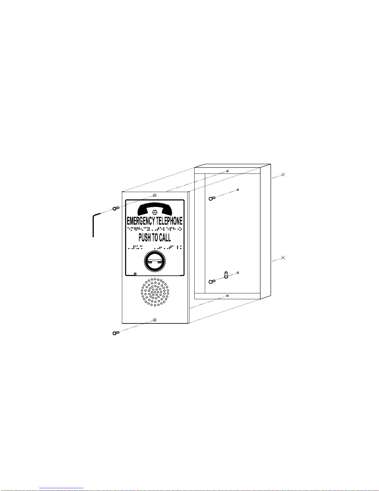
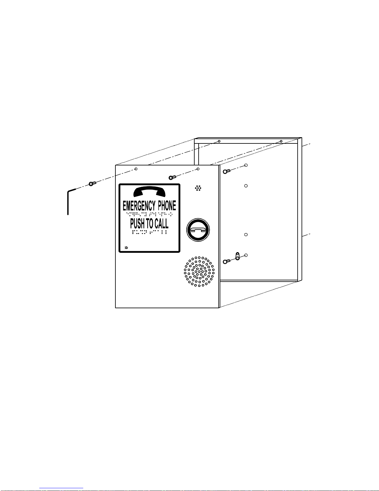
K-Phone ET401 Emergency Speakerphones are available in four
different mounting styles. See pages 7 - 10 for more detailed
information.
Sentry (ET401A) - surface or phone box mount
Fortress (ET1401A) - flush mount
Commander (ET401A-OEM) - operating panel mount
Liberator (ET401A-LP) - surface or phone box mount
Pre-Installation Checklist
q
Read this manual completely before installation.
q
Check that you have a live telephone line (24 or 48 VDC, CO or
PBX) installed and terminated at the elevator machine room.
Tools Required:
qsmall flathead screwdriver
q1/4” nut-driver
qwire cutters
qlong-nosed pliers
qdrill and pilot bit for #8 sheet metal screw
qDigital Multimeter (DMM)
q9 volt battery (for programming)

Page 5
Wiring
We strongly recommend that the wires used to supply the telephone
line to K-Tech emergency speakerphones be 20 AWG shielded,
twisted pair.
The shield must be continuous from the speakerphone through the
traveling cable to the incoming telephone line termination. Make
sure the shield is connected to a
true earth ground at one end
only!
This will minimize the interference from AC inductance and RF
(radio frequency).
Telephone Lines
For best operation, each K-Tech K-Phone ET401 Emergency
Speakerphone must be installed on an analog touch-tone telephone
line. Compatible line types are standard analog two-wire central
office lines (POTS) from the local telephone company or most
internal PBX systems.
The K-Phone ET401 Emergency Speakerphone should be
installed on a dedicated telephone line. Sharing a telephone line
with other devices (e.g. fax machine, alarm system, another
telephone, etc.) could affect code compliance and/or cause the
K-Phone ET401 Emergency Speakerphone to malfunction.
The telephone line will be assigned a telephone number which
allows the called party to call back to the location of the emergency.
Take care to note this number and supply it to the called party.
Telephone Line Specifications
Line Type Standard two-wire voice analog
Line Voltage 24 VDC minimum on-hook
Loop Current 30 mA minimum

Page 6
Wiring Diagram
Connect
Telephone
Line shield to
true earth
ground at
one end
only!
TELEPHONE LINE
MICROPHONE
SPEAKER
Increase
VOL.
9
6
3
#*
1
4
7
2
5
8
0
BUT
LED
+
-
9.0 VDC IN
REMOTE
LED
2V 7mA
PHONE
LINE
R
T
REMOTE
BUTTON
Dry
Contacts
12 - 30V
ONLINE
PROG
AUX
POWER
RINGS
5 -
7 -
9 -
K-Tech International Inc.
Part # PCB009 Rev D.
SERIAL #

Page 7
Installation
Sentry (ET401A)
1.
Use the 3/32” Allen wrench (included) to unscrew the fasteners
and remove the rear enclosure.
2.
Using the rear enclosure as a template, mark the mounting
screw hole locations.
3.
Drill holes for two #8 screws (included).
4.
Mount the rear enclosure placing the Ground Lug under one of
these mounting screws.
WHEN LIGHT
FLASHES
HELP IS ON
THE WAY
K-Tech International, Inc, Torrington, CT
5.
Proceed to Settings on page 11.
6.
Proceed to Programming on page 12.
7.
Proceed to Operation and Testing on page 16.

Page 8
Liberator (ET401A-LP)
1.
Use the 3/32” Allen wrench (included) to unscrew the fasteners
and remove the rear enclosure.
2.
Using the rear enclosure as a template, mark the mounting
screw hole locations.
3.
Drill holes for two #8 screws (included).
4.
Mount the rear enclosure placing the Ground Lug under one of
these mounting screws.
WHEN LIGHT FLASHES
HELP IS ON THE WAY
K-Tech International, Inc, Torrington, CT
5.
Proceed to Settings on page 11.
6.
Proceed to Programming on page 12.
7.
Proceed to Operation and Testing on page 16.

Page 9
Fortress (ET1401A)
1.
Determine the mounting location and cut a 10” x 7” (25 cm x 18
cm) opening to allow for the back enclosure.
2.
Using the faceplate as a template, mark the mounting screw
hole locations.
3.
Drill holes for four #8 security screws (included).
K-Tech International, Inc, Torrington, CT
WHEN LIGHT FLASHES
HELP IS ON THE WAY
4.
Remove the enclosure by removing the two nuts that secure it.
5.
Proceed to Settings on page 11.
6.
Proceed to Programming on page 12.
7.
Remount the enclosure, placing the Ground Lug under one of
the nuts that secure it.
8.
Mount the unit over the opening using the #8 security screws
(included).
9.
Proceed to Operation and Testing on page 16.

Page 10
Commander (ET401A-OEM)
1.
Using the faceplate as a template, align the microphone and
speaker with the grill pattern; mark and install the mounting
studs.
2.
Mount the faceplate tightly against the back of the COP to avoid
feedback between the microphone and speaker.
MICROPHONE
SPEAKER
Increase
VOL.
9
6
3
#*
1
4
7
2
5
8
0
BUT
LED
+
-
9.0 VDC IN
REMOTE
LED
2V 7mA
PHONE
LINE
R
T
REMOTE
BUTTON
Dry
Contacts
9-24V
ONLINE
PROG
AUX
POWER
RINGS
5 -
7 -
9 -
K-Tech International Inc.
Part # PCB009 Rev D.
SERIAL #
3.
Connect the normally open (NO) contacts of the push-button to
the terminal labeled REMOTE BUTTON (see Wiring Diagram on
page 6).
4.
Connect the visual indicator to the terminals labeled REMOTE
LED taking care to follow the correct polarity.
5.
Proceed to Settings on page 11.
6.
Proceed to Programming on page 12.

Page 11
Settings
Number of Rings Incoming
The K-Phone ET401 Emergency Speakerphone will automatically
answer an incoming call after either 5, 7, or 9 rings. You can easily
set this number of rings by installing the jumper in the appropriate
location. Factory default is 5 rings.
MICROPHONE
SPEAKER
Increase
VOL.
PHONE
LINE
R
T
REMOTE
BUTTON
Dry
Contacts
RINGS
5 -
7 -
9 -
SERIAL #
Install jumper
here

Page 12
Programming
Easy, voice prompted programming directs the entry of feature
settings and plays back the information entered for confirmation.
Programming is done via the built-in keypad, or remotely by any
touch-tone telephone.
NOTE: A 9 VDC battery is required for programming using the
built-in keypad.
NOTE: Be sure prompt has completed before entering next
command.
NOTE: If there is no input within 9 seconds of an input request,
the unit will prompt, “Enter star, then program feature number”.
On-Site Programming:
1.
Connect 9 VDC battery to header on phone circuit board.
2.
Set ONLINE/PROG switch to PROG and wait for tone.
3.
Enter Program Mode (see below).
4.
Follow the instructions listed for each individual feature you wish
to set or change (see pages 12 - 15).
5.
Exit Program Mode (see page 15).
6.
Set ONLINE/PROG switch to ONLINE.
7.
Disconnect 9 VDC battery from phone circuit board.
Remote Programming:
1.
Call into the K-Phone ET401 Emergency Speakerphone.
2.
Once the call is answered, Enter Program Mode (see below).
3.
Follow the instructions listed for each individual feature you wish
to set or change (see pages 12 - 15).
4.
Exit Program Mode (see page 15).
5.
When finished, enter “ * # ” (star pound) once to exit program
mode, then press “ * # ” (star pound) a second time to shut it off.
Enter Program Mode
Activity Enter Voice Prompt
Enter Program Mode * 7 "Enter Security Code"
Enter four digit Security Code 1 2 3 4
(Factory
Default)
"Enter star then Program
Feature number"

Page 13
Voice Announcement 1
Voice Announcement 1 will automatically play when the emergency
call is answered. Once the 10 second message has played, two-
way communication is possible.
For best results, record the announcement in
a noise free
environment
. Speak clearly into the microphone or telephone
handset.
Sample Message:
“There is an emergency in elevator 4 at 123 Main Street. Please
initiate entrapment procedures. Press star-one to repeat this
message.”
Activity Enter Voice Prompt
Record Voice
Announcement 1 * 1 "Press pound to start
recording"
Press " # " (pound); record
announcement with
speakerphone's built-in
microphone
#
Record
announce-
ment
(after 10 seconds) "Stop",
plays back recorded
message, then "Enter star
then program feature number"
Eliminating Voice Announcement 1
If you have another means in place to identify the origin of the
emergency call, you can eliminate Voice Announcement 1.
Activity Enter Voice Prompt
Eliminate Voice
Announcement 1 * 1 "Press pound to start
recording"
DO NOTHING
wait for unit to time out (after 9 seconds) "Stop", then
"Enter star then program
feature number"

Page 14
Voice Announcement 2
Voice Announcement 2 can be recorded to supply the called party
with additional information. To play this announcement, the called
party must hit “ * 2 ” (star two) on their telephone keypad.
Activity Enter Voice Prompt
Record Voice
Announcement 2 * 2 "Press pound to start
recording"
Press " # " (pound); record
announcement with
speakerphone's built-in
microphone
#
Record
announce-
ment
(after 10 seconds) "Stop",
plays back recorded
message, then "Enter star
then program feature number"
Telephone Numbers
The K-Phone ET401 will dial up to five emergency telephone
numbers if the line is busy or there is no answer. It will continue to
cycle until the call is answered (twelve attempts total).
Program the emergency numbers into the appropriate memory
locations in the order you want them to be dialed (Memory Location
1 dials first, Memory Location 2 dials second, etc.).
Activity Enter Voice Prompt
Program Telephone Number * 3 "Enter location of phone
number"
Enter Memory Location for
phone number 1"Enter phone number, then
press pound"
Enter phone number up to 20
digits including pauses
(" * "= 1 1/2 second pause)
1-234-567-
8900
#
"Please verify…", verbally
confirms number entered,
beeps as number is stored,
then "Enter star then Program
Feature number"
NOTE: Enter “ * ” (star) to insert a 1 1/2 second pause.
NOTE: Some internal telephone (PBX) systems require an
“access digit” to secure an outside (CO) telephone line
(e.g. “ 9 ”). A Pause may be needed between the “ 9 ” and the
rest of the telephone number. (e.g. 9-PAUSE-1-234-567-8900)

Page 15
Timer Minutes
This is the amount of time the K-Phone ET401 Emergency
Speakerphone will remain on (unless the called party extends the
timer).
Activity Enter Voice Prompt
Program Timer Minutes * 4 "Enter timer minutes"
Enter time desired from 01 to
99 minutes, or "0 0" for infinite
timer
0 5 "Zero five", beeps as number
is stored, then "Enter star
then Program Feature
number"
Number of Rings Outgoing
Sets the number of rings or “busy” signals the K-Phone ET401
Emergency Speakerphone will allow before dialing the next
Telephone Number.
Activity Enter Voice Prompt
Program Number of Rings
Outgoing * 5 "Enter Number of Rings
Outgoing"
Enter number of rings desired
from 1 to 9 4"Four", beeps as number is
stored, then "Enter star then
Program Feature number"
Security Code
This sets the Security Code for making changes to the
programming.
Activity Enter Voice Prompt
Program Security Code * 9 "Enter Security Code"
Enter new four-digit Security
Code 1 2 3 4 "One two three four", beeps
as number is stored, then
"Enter star then Program
Feature number"
Exit Program Mode
Activity Enter Voice Prompt
Exit Program Mode * # "Program complete"
NOTE: Be sure to set ONLINE/PROG switch to ONLINE.

Page 16
Operatio
n
and Testing
1.
Press the activating push-button.
The visual indicator will turn on, dial tone will be heard for a few
seconds, then the first programmed emergency telephone
number will dial. If busy or there is no answer, the second
number will be dialed, etc.
Once answered, the visual indicator will turn off as Voice
Announcement 1 plays. The visual indicator will then turn back
on and two-way communication will be possible.
NOTE: Voice Announcement 1 will NOT be heard at the K-Phone
ET401 Emergency Speakerphone.
2.
Speak with the called party.
Verify two-way communication and that Voice Announcement 1
was heard clearly; adjust the volume control.
3.
Have the called party press “ # ” (pound).
The visual indicator will start to flash.
NOTE:
When the Timer Minutes runs down to 30 seconds, the
unit will prompt “Press pound for two timer minutes.” The
operator may keep the K-Phone ET401 Emergency
Speakerphone on for an additional two minutes by hitting
“ # ”
(pound) on their telephone keypad.
4.
Have the called party hang up.
The K-Phone ET401 Emergency Speakerphone will
automatically shut off via the telephone line disconnect (CPC)
signal.
NOTE: If this signal is not present on the line, the K-Phone
ET401 will shut off via the timer, or the called party can hit
“ * # ”
(star pound) on their telephone keypad to turn the phone
off manually.
5.
Have the answering party call back to the K-Phone ET401
Emergency Speakerphone.
It will ring the selected number of rings, then automatically
answer the incoming call and allow two-way communication.
6.
Have the called party press “ * 1 ” (star one).
Voice Announcement 1 will replay.
7.
Finish mounting the K-Phone ET401 and retest.
NOTE: Make sure wiring does not physically interfere with
components when finalizing installation.

Page 17
Troubleshooting
When the activating push-button is pressed, there is no
response from the K-Phone ET401 Emergency Speakerphone
(i.e. no dial tone is heard, the visual indicator doesn’t light).
1.
Check the connections to the microphone, speaker, LED, and
button (N.O. contacts)
2.
Check that there is a “live” telephone line connected, and that it
meets the minimum line requirements (see page 5). If there is
no telephone line voltage in the elevator car, check for line
voltage in the machine room and verify the connection.
When the K-Phone ET401 Emergency Speakerphone is
activated, dial tone is heard, but no emergency telephone
number is dialed.
1.
Verify that the emergency telephone numbers have been
programmed (see page 14).
The K-Phone ET401 Emergency Speakerphone shuts off while
dialing or in the middle of conversation, or cycles on and off.
1.
Check that the Timer Minutes is set long enough to allow for the
conversation (see page 15). The called party can extend this
timer in five minute increments when they hear a “beep” on the
line.
2.
If the speaker volume is set too high, there may not be enough
power on the telephone line to support it. Reduce the volume
and retest.
The K-Phone ET401 Emergency Speakerphone stays on after
the called party hangs up.
1.
Check to see if the telephone line supplies a disconnect (CPC)
signal. If this signal is not present on the line, it will shut off
automatically by the built in timer (see Timer Minutes on page
15).
The K-Phone ET401 Emergency Speakerphone false activates
and calls out when the elevator moves, when doors open/close,
when floor buttons are pushed, etc.
1.
The K-Phone ET401 Emergency Speakerphone must be
installed on properly shielded and grounded wires (see Wiring
on page 5).
For Technical Support call
1-800-993-9399 or (860) 489-9399

Page 18
Specifications
Power
Telephone line: 24 VDC minimum on-hook
voltage; 30 mA minimum loop current
9 volt battery required for programming with
integral keypad
Circuit Protection
Varistor lightning suppressor and full wave
polarity guard
Dialing
Five numbers up to 20 digits each (including
1 1/2 second pauses); up to twelve attempts
Programming
Integral keypad entry or remote with any
touch-tone telephone
Voice Announcement
Voice activated, 10 second duration
Shut-Off
Programmable 1-99 minute timer - may be
extended in 5 minute increments (warns
called party with beep 30 seconds before
time-out); automatic shut-off with disconnect
(CPC) signal (if provided)
Incoming Call Answer
Automatically answers incoming calls
REN = [1.0] (68 to 15.8 Hz)
Visual Indicator
On when activated; can be made to flash by
called party hitting “#” (pound) on their
telephone keypad
FCC Registration
ERCUSA-44577-TE-T
Dimensions
Sentry (ET401A) 9 1/2" H x 4 3/4" W x 2" D
(241 mm x 121 mm x 51 mm)
Liberator (ET401A-LP) 9 1/2" H x 6 5/8" W x 1" D
(241 mm x 175 mm x 26 mm)
Fortress (ET1401A) Faceplate 12 1/2 “ H x 10” W x 1/8" D
(318 mm x 254 mm x 4 mm)
Enclosure 9 5/8" H x 6 1/2" D x 2 1/2" D
(245 mm x 165 mm x 64 mm)
Commander (ET401A-OEM) 9 1/2" H x 4 3/4" W x 1 3/4" D
(241 mm x 121 mm x 45 mm)
NOTE: The electronics in these products has been tested to
Class B of Part 15 of the FCC rules. However, it has not been
formally registered as a Class B device.
WARNING!:
This product is intended for INDOOR USE ONLY.
For more information on moisture resistant units, please
contact our Customer Service Department at 1-800-993-9399.

Page 19
Code Compliance
K-Tech has taken great care in ensuring that our telephone
equipment meets all code requirements. There are however
additional requirements that have to be met in order for the
installation and operation to pass code. We will attempt to list
requirements pertaining to the installation of our telephone
equipment. The ultimate responsibility is yours, however. Consult
local codes to be sure your installation complies.
1.
Telephone equipment must be mounted at the proper height for
people who use wheel chairs.
2.
Make sure the called party knows how to make the visual
indicator function. This signal is for the hearing impaired and
means that help is on the way (see our “Answering Phone
Instructions” card).
3.
Make sure the called party can determine the origin of the call
without interaction from the caller. This is accomplished by using
the Voice Announcement feature or by using a caller-ID system.
4.
When installing K-Phone ET401s inside an elevator phone
cabinet you should install a sign with raised and Braille lettering
(such as model LB014) on the outside. A door handle allowing
the physically impaired to open the door (such as model ET-
TBH) should also be installed.

Page 20
FCC Notice for Part 68
This device has been granted a registration number by the Federal
Communications Commission, under Part 68 rules and regulations
for direct connection to the telephone lines. In order to comply with
these FCC rules, the following instructions must be carefully read
and applicable portions followed completely.
1.
This equipment complies with Part 68 of FCC rules. A label
located on an outside surface of this equipment contains,
among other information, the FCC registration number and
ringer equivalency number (REN). If requested, provide this
information to your telephone company.
2.
The registration jack USOC for the equipment is RJ11C.
3.
The REN is useful to determine the quantity of devices that may
be connected to the telephone line. Excessive RENs on the
telephone line may result in the devices not ringing in response
to an incoming call. In most, but not all areas, the sum of the
RENs of all devices should not exceed five (5). To be certain of
the number of devices that may be connected to a line, as
determined by the total RENs, contact the telephone company.
4.
If your telephone equipment causes harm to the telephone
network, the telephone company will notify you in advance that
temporary discontinuance of service may be required. But if
advance notice isn’t practical, you will be notified as soon as
possible. You will be advised of your right to file a complaint with
FCC if you believe it is necessary.
5.
Your telephone company may make changes in its facilities,
equipment, operations, or procedures that could affect the
operation of your equipment. If they do, you will be given
advance notice so as to give you opportunity to maintain
uninterrupted service.
6.
If you experience with this equipment, please contact K-Tech
International Customer Service at 1-800-993-9399 for repair/
warranty information. If your equipment is causing harm to the
telephone network, the telephone company may request that
you disconnect the equipment until the problem is resolved.
7.
This equipment may not be used on public coin service
provided by the telephone company. Connection to party lines is
subject to state tariffs. (Contact your state public utility
commission or corporation commission for information.)
This manual suits for next models
3
Table of contents
Other K-Tech Telephone manuals