KADANT LIQUI-MOVER LMHT-500 SERIES User manual

LIQUI-MOVER®PUMP
LMHT-500 SERIES
HANDBOOK
Kadant Johnson Inc., 805 Wood Street, Three Rivers, MI 49093 USA 269-278-1715 fax: 269-279-5980 www.kadant.com
LMHT-500 Handbook-4002

What is a Liqui-Mover®Pump?
A Liqui-Mover pump is a positive displacement pressure powered pump with a minimum of moving parts.
The pumping action is accomplished using a positive pressure to push the liquid from the pump tank into
the return line. The Liqui-Mover pump can handle high temperature and high pressure condensate without
difficulty.
The float actuated Liqui-Mover pumps are available in 3 basic models. They are available in many configu-
rations, from individual components that are field assembled to complete packaged systems ready for con-
nection to field piping. A basic Liqui-Mover pump consists of a receiver/reservoir, pump tank, inlet and out-
let check valves, snap acting float operated level control, and various other fittings.
How a Liqui-Mover Pump Works
In describing “How a Liqui-Mover Pump Works”, it is best to view it as three distinct stages. These stages
are described below:
Float Activated Level Control
STAGE ONE:
In the fill cycle, fluid flows from the receiv-
ing chamber (A) through the inlet check
valve (B) into the pumping chamber (C),
and raises the float (D). The vent port (E)
is open to equalize pressure between the
receiving chamber and pumping chamber.
STAGE TWO:
When the float reaches its highest level, a
spring assembly (F) activates the linkage
(G), which closes the vent port (E) and
opens the motive pressure port (H). When
the pressure in the pumping chamber
exceeds discharge line pressure, the dis-
charge check valve (I) opens, and the dis-
charge cycle begins. As the fluid level goes
down, so does the float. During this cycle,
incoming fluid is stored in the receiving
chamber.
STAGE THREE:
Once the float (D) reaches its lowest
position, the linkage (G) closes the
motive pressure port and opens the vent
port (E) so the two chambers can equal-
ize in pressure to start the cycle again.
A
E
B
D
C
E
H
G
F
I
E
D
G

Installation
Receipt of Equipment
The float assembly has been adjusted and tested at the factory. Additional items such as the inlet baffle (if
supplied), check valves, level gauge glass, cycle counter, and insulation jacket will be packaged separately
in a carton shipped with the unit.
Setting the Unit
On LOOO models, the pump tank may be anchored to the floor using the holes in the mounting feet.
On LROO models, you will also need to install a Johnson supplied receiver. The receiver is held in saddles
with ‘U’ bolts supported by (4) pipes on floor flanges. The floor flanges have mounting holes for attachment
to the floor.
On LRSM models, the entire skid should be supported. Mounting holes may be drilled through the skid for
attachment to the floor.
All tanks should be installed level.
Piping
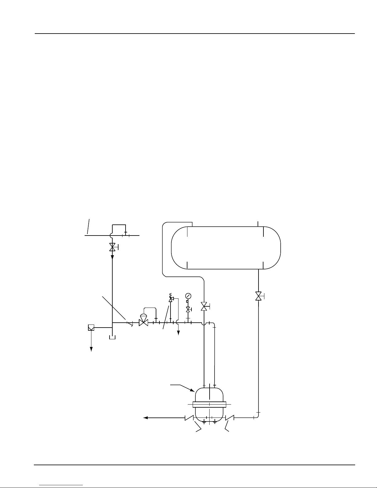
On LROO and LRSM models, the Johnson supplied receiver will normally have (3) top connections for: con-
densate inlet, atmospheric vent, and pressure gauge. For ‘closed systems’ (no atmospheric vent), an air
eliminator and safety relief valve will need to be installed. On LOOO models, the condensate is piped direct-
ly to the inlet check valve from an existing receiver or pipe accumulator.
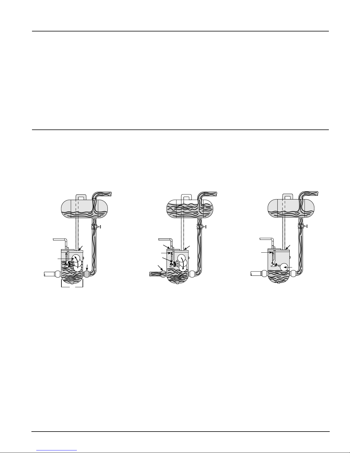
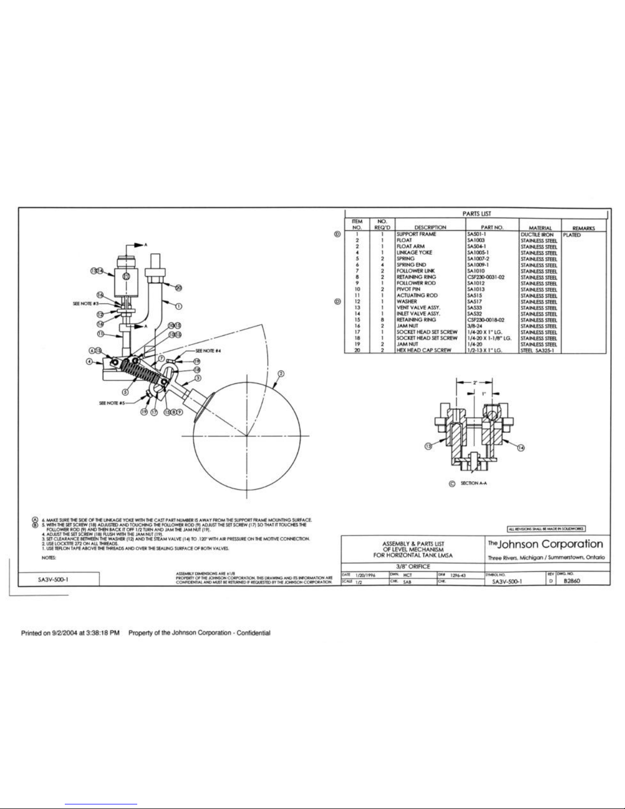
Refer to the Johnson assembly drawing that accompanies this product for typical piping diagrams. The inlet
baffle (if supplied) must be installed into the pump tank prior to installing the inlet check valve.
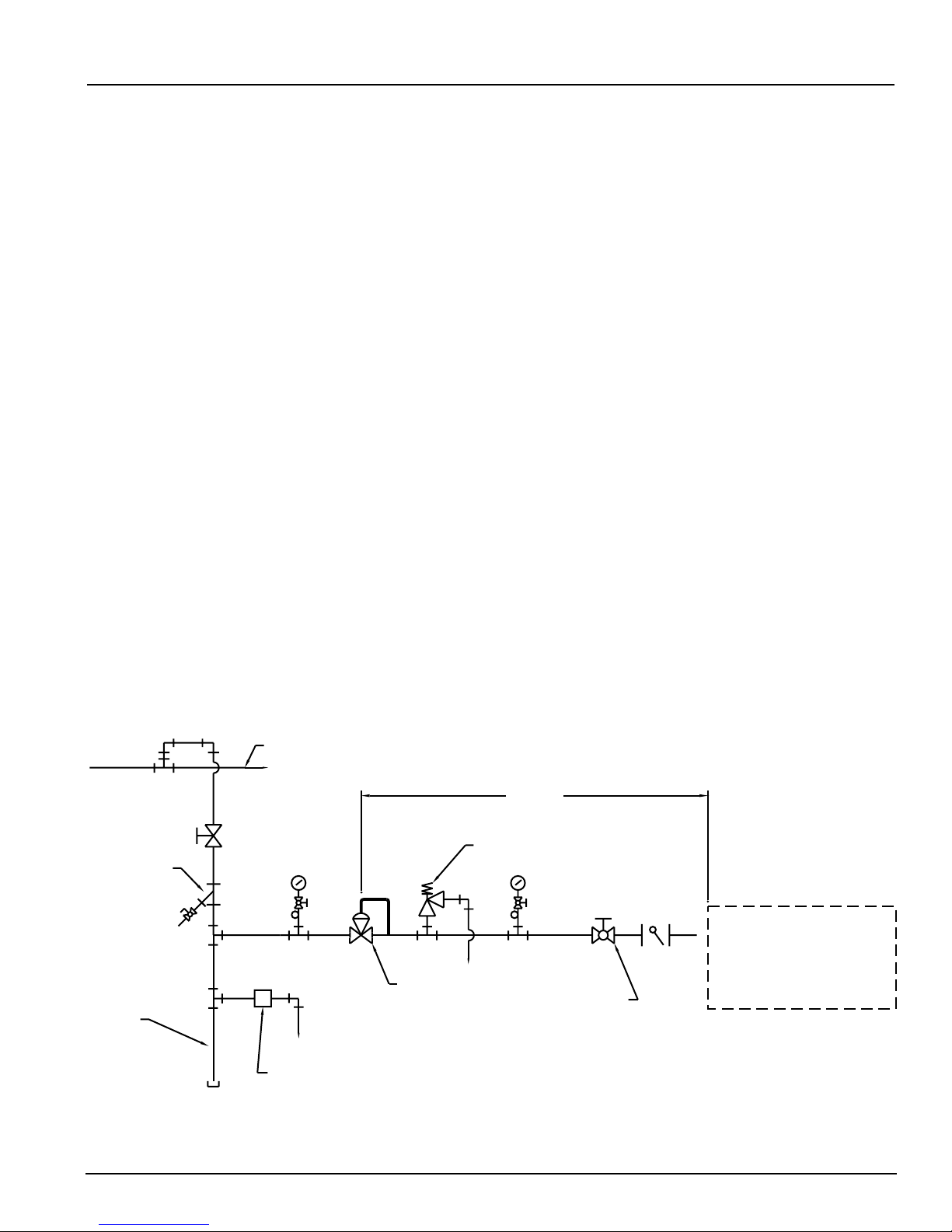
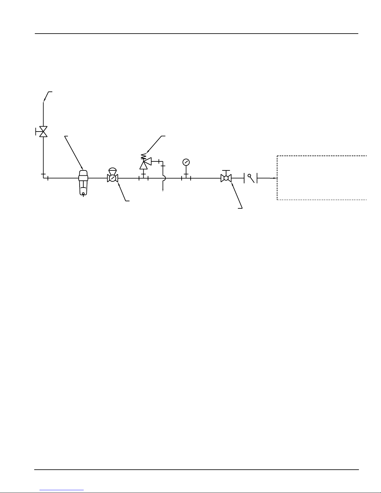
The motive gas (normally steam or compressed air) is piped to the float assembly (1/2˝ npt connection)
through a strainer and a pressure reducing valve.
The equalization (vent) connection on top of the pump tank should be connected to the receiver. The equal-
ization line should not be reduced in size and be installed with minimal restrictions. If the equalization line
is more than 36” in length, the pipe size should be increased at least three pipe sizes. In cases where a
combustible liquid is being handled or the motive used is combustible, the vent must go to a flare or flame.
For LROO and LOOO models, friction loss through the piping should be kept to a minimum. Therefore, pipe
reducers should not be used and pipe runs kept to a minimum. All hand valves should be full port if at all
possible. It is recommended that isolation hand valves be installed to aid in the maintenance of the units.
Some suggested locations are: upstream of the inlet check valve, downstream of the outlet check valve, in
the motive line ahead of the strainer, in the equalization line between the float assembly and the receiver,
and ahead of the pressure reducing valve.

Pressure Reducing Valve Installation
A pressure reducing valve (PRV) should be installed in the motive pressure line to regulate how fast the
Liqui-Mover pump discharges the condensate out of the pump tank. Normally the motive pressure setting
will be approximately 20 psig higher than the back pressure to achieve a proper discharge time. The dis-
charge time should be a little less than the time it takes to fill the pump tank under maximum condensing
load.
Here are some guidelines to be followed when installing a PRV in conjunction with a Liqui-Mover pump:
1. Never install a PRV immediately adjacent to the Liqui-Mover pump. The shock caused by the
sudden opening and closing of the motive valve will ultimately damage the PRV. We recom-
mend a distance of 20-25 feet between the PRV and the Liqui-Mover pump, where the pipe
size is the same as the motive inlet connection. A larger diameter pipe of a shorter length that
has an equivalent volume is acceptable. The PRV should be sized by a pressure reducing
valve manufacturer or representative.
2. A safety relief valve should be installed downstream of the PRV to prevent over-pressurization
of the motive medium. The safety relief valve should be sized by a safety relief valve manu-
facturer or representative.
3. When steam is the motive pressure, a drip trap, dirt leg, and strainer should be installed ahead
of the PRV. The drip trap should not be piped to the Liqui-Mover pump. When compressed
air is the motive pressure, a liquid drainer, dirt leg, and strainer should be installed ahead of
the PRV. The liquid drainer should not be piped to the Liqui-Mover pump.
4. The piping from the PRV outlet to the Liqui-Mover pump should be sized to minimize the pres-
sure drop under ‘flow conditions’.
5. A throttling valve should be installed immediately ahead of the Liqui-Mover pump so it can be
used in conjunction with the PRV to adjust the Liqui-Mover pump discharge time. Typically the
throttling valve is a globe valve.
The above sketch is for reference only. Always consult with the PRV and safety relief valve manufacturer
or representative for proper sizing and application of their products.
Motive Inlet
of Liqui-Mover
Pump
Throttle Valve
(Globe)
PRV
Drip Trap(Steam) or
Liquid Drainer(Air)
Y Strainer
20' to 25'
Motive Supply Header - Steam or Compressed Air
Safety Relief Valve
(Piped to safe location)
Dirt Leg

Installation Diagram for Liqui-Mover Pump with Compressed Motive
To Motive Inlet
of Liqui-Mover
Pump
Throttle Valve
(Globe)
Motive - Compressed Air Supply
Filter w/ Auto Drain
Regulator w/ Gage
Safety Relief Valve
(When Needed)
1. This is the recommended piping for a Liqui-Mover pump with compressed motive.
2. The air should be clean, dry and regulated so that the Liqui-Mover pump discharges in the
recommended time.
3. The above parts furnished by customer.

Printed on 4/8/2014 at 8:37:28 AM Property of Kadant Johnson - Confidential

Start-Up Instructions For LMHT-500 Liqui-Mover Pump
1. On systems that are not pre-piped, inspect the inlet and outlet check valves for proper flow
direction. Refer to the Liqui-Mover pump assembly drawing and parts list.
2. If the receiver or pump chamber contains sub-cooled condensate, this needs to be drained
prior to start-up.
3. Open any additional maintenance hand valves that were installed for maintenance.
4. Open any hand valves in the discharge line. Open the vent line hand valve. Open the hand
valves that supply condensate to the pumping chamber.
5. To set the discharge cycle time, a PRV is recommended and should be set for approximately
20 psig above the back pressure. If a globe valve is used in conjunction with a PRV, the globe
valve should be fully open. If a PRV is not used, the globe valve should be opened slightly.
After the system is operating this valve should be adjusted so the pump time is slightly less
than the fill time.
6. When the pumping chamber is full, the level control will automatically close the vent valve and
open the high pressure motive valve, allowing motive to enter the pumping chamber and con-
densate to flow out the discharge line.
7. When the pumping chamber is empty, the level control will automatically close the motive valve
and open the vent valve, allowing the pumping chamber to vent into the receiver, equalize
pressure, and begin filling.
Pumping
Chamber
Dirt
Leg
Drip
Tr a p
Strainer
PRV Gate
Valve
Receiver
May Be JOCO ASME Labeled
Receiver, Existing Receiver, or
Oversized Pipe Header, Etc.
Vent Line Inlet
Motive Header
Outlet
Check Valve
Inlet
Check Valve
To Condensate
Return Line
Safety Relief
as Required
PRV
TYPICAL INSTALLATION SKETCH

Printedon8/28/2009 at 9:23:27 AMPropertyofKadant Johnson-Confidential


LIQUI-MOVERPUMP
REPAIR KITS
RK-LMSA Motive and Vent Valves
ITEM QTY PART NAME PART NUMBER MATERIAL REMARKS
12 1 Washer SA517 Stn. Stl.
13 1 Vent Valve Assembly SA533 Stn. Stl.
14 1 Inlet Valve Assembly SA532 Stn. Stl.
RK-SA3V-500 Repair Kit
ITEM QTY PART NAME PART NUMBER MATERIAL REMARKS
4 1 Linkage Yoke SA1005-1 Stn. Stl. –
5 2 Spring SA1007-2 Stn. Stl. –
6 4 Spring End SA1009-1 Stn. Stl. –
7 2 Follower Link SA1010 Stn. Stl. –
8 2 Snap E Ring CSF230-0031-02 Stn. Stl. –
9 1 Follower Rod SA1012 Stn. Stl. –
10 2 Pivot Pin SA1013 Stn. Stl. –
11 1 Actuating Rod SA515 Stn. Stl. –
12 1 Washer SA517 Stn. Stl. –
13 1 Vent Valve Assembly SA533 Stn. Stl. –
14 1 Inlet Valve Assembly SA532 Stn. Stl. –
1 O-Ring CSS825-281-E EPR –
15 8 Retaining Ring CSF230-0018-02 Stn. Stl. –

Page 1 - General Troubleshooting Float Actuated LMPs LMPFA-TS 0904-01
OBSERVATION PROBABLE CAUSE REMEDY
1. Liqui-Mover pump fails to fill. 1. Increase in liquid level in
receiver, possible flood in
receiver.
Obstruction in fill line, valve closed,
inlet check backwards.
Inspect fill line for closed valve, inlet
check in reverse, or obstruction in fill
line. Refer to Assembly & Parts List
Drawing.
2. Receiver empty,
Liqui-Mover pump level
fluctuating.
Receiver pressure greater than
pressure in discharge line.
If unit has been in operation for a
period of time without problems,
check for traps blowing through. If
new installation, receiver pressure
may be greater than anticipated. Back
pressure may be less than anticipated.
A 2-Way control valve may be
required in discharge line.
2. Liqui-Mover pump fills too
slow.
1. No liquid level in receiver. Load to unit not as great as
anticipated.
No action required.
2. Receiver flooding. Obstruction or restriction in fill line. Inspect fill line for partially closed
valve or defective check valve.
Inspect fill line for proper size fittings
and pipe. Refer to Assembly and
Parts List Drawing for specific unit.
3. Receiver flooding. Restriction in vent line, motive and
vent valve assembly out of
adjustment.
Inspect vent line for partially closed
valve, proper size fittings and pipe.
Refer to Assembly and Parts List
Drawing.
GENERAL TROUBLESHOOTING OF
FLOAT ACTUATED LIQUI-MOVERPUMPS

Page 2 - General Troubleshooting Float Actuated LMPs LMPFA-TS 0904-01
OBSERVATION PROBABLE CAUSE REMEDY
3. Liqui-Mover pump fills very
rapidly.
1. Unit cycling almost
normally, receiver flooding.
Defective check valve in discharge line
and/or fill line. Possible back flow to
Liqui-Mover pump.
Inspect discharge line check valve and
fill line check valve. Refer to
Assembly and Parts List Drawing.
4. Noise in or at fill line check
valve.
1. Vibration and water hammer
at fill line check valve.
Cold condensate. Inspect for cold condensate. Throttle
flow control valve, ahead of Liqui-
Mover Pump assembly. Refer to
Assembly and Parts List Drawing,
and start-up procedure.
5. Liqui-Mover pump discharges
very rapidly.
1. Water hammer in discharge
line.
Motive pressure too high. Throttle flow control valve or install
pressure reducing valve. See start-up
procedure.
2. Receiver flooding, rise in
receiver pressure during
discharge.
Defective check valve in fill line.
Discharging condensate back into
receiver.
Inspect fill line check valve. Refer to
Assembly and Parts List Drawing.
6. Liqui-Mover pump discharge
cycle too long.
1. Possible receiver flooding. Flow control valve throttled too much. No action required, if receiver not
flooding. If receiver flooding, adjust
flow control valve for discharge of
10 - 15 seconds (approx.).
2. Receiver flooding. Restriction or increase of back
pressure in discharge line.
Inspect discharge line for partially
closed valve(s), obstructions or
change in pressure. A pressure
increase may require adjustment of
flow control valve to reduce discharge
time. Inspect discharge check valve.

Page 3 - General Troubleshooting Float Actuated LMPs LMPFA-TS 0904-01
OBSERVATION PROBABLE CAUSE REMEDY
3. No motive pressure flow.
Receiver flooding.
Motive supply failure, obstruction in
motive supply line.
Inspect for motive supply pressure,
closed valve, or obstruction in motive
supply line. Inspect strainer.
4. Inlet Valve noisy. Condensate in motive supply line. Inspect motive supply line for
condensate. Check drip trap. Refer to
Assembly and Parts List Drawing.
5. Receiver pressure increase
during discharge.
Valve assembly out of adjustment.
Motive pressure leakage into receiver,
defective Fill Check Valve.
Refer to Float Mechanism Assembly
Drawing.

LMHT-SA
PREVENTATIVE MAINTENANCE
CHECK LIST
HOW OFTEN CHECK REFERENCE
1 Year 1. Check anode in receiver tank (if
applicable).
Drain tank – remove anode by
unscrewing anode plug on the receiver
tank end. If over 60% eaten away,
replace.
2. Clean gauge glass when required. Disassemble and pull clean cloth
through glass with cleaning wire.
3. Drain tank and flush to remove
residue.
Remove drain plug in the bottom of
tank and flush. Replace plug
afterwards.
4. Pull internal mechanism and inspect
for wear on pins and linkage and for
buildup on the float.
Remove cap screws in top flange and
remove internal mechanism and
inspect.
CAUTION: Before performing any of the above maintenance checks, shut off all steam and
condensate lines connected to the unit.
Table of contents
Popular Water Pump manuals by other brands

BLACKMER
BLACKMER X1220A Installation, operation and maintenance instructions

Delta Environmental Products
Delta Environmental Products D4E Series owner's manual

Xylem
Xylem Goulds NPE Installation, operation and maintenance instructions

Seko
Seko AKTUA ATR-05S Operation & maintenance manual

Grundfos
Grundfos MAGNA3 25-100 (N) instructions

Bestway
Bestway FLOWCLEAR 58391 owner's manual