KAEL Muhendislik Elektronik VARkombi-12-PC-TFT-OG-SOLAR User manual

KAEL Mühendislik Elektronik
Tic. ve San. Ltd.Şti.
Power Factor Controller
12 Step
VARkombi-12-PC-TFT-OG-SOLAR
Connection type selective
VARkombi-12-PC-TFT-OG-SOLAR
Solar Plant compensation

Contents
Introduction .......................................
Warnings ...........................................
Specifications......................................
General ..............................................
Step Panel ..........................................
Ma ing the Connections .......................
Connections .......................................
Alerts .................................................
Commisioning .....................................
Main Screens ......................................
% Instant Consumption........................
CosФ ..................................................
PF Power Factor .................................
Σ Accumulated Energy Ratios................
Steps ..................................................
1. MENU ................................................
1.1 Harmonics ..........................................
1.2 Step Indicator .....................................
1.3 Voltage, Current, Frequency.................
1.4 Power ................................................
1.5 Energy ...............................................
1.6 Counter Index ....................................
1.7 Settings .............................................
1.7.1 Measurement Types .........................
1.7.2 Target CosФ .......................................
1.7.3 Switch on(decharge) Time ...................
1.7.4 Switch off Time ...................................
1.7.5 Switch min. Time ...............................
1.7.6 Limit of Inductive Penalty.....................
1.7.7 Limit of Capacitive Penalty....................
1.7.8 Current Transformer (Primary) Value ...
1.7.9 Number of Steps .................................
1.7.10 Advanced Set-up Menu.........................
1.7.10.1 ΔT on Transition(Delay) Time...............
1.7.10.2 ΔT off Transition(Delay) Time..............
1.7.10.3 Current Flow Direction Detection ..........
1.7.10.4 Fast Step Mode....................................
1.7.10.5 Step Parameters..................................
1.7.10.5.1 Continuous Step Power Detection ........
1.7.10.5.2 Constant Step Function ......................
1.7.10.5.3 Step Synch. Time Sharing ....................
1.7.10.5.4 Enter Step Powers ..............................
1.7.10.5.5 Delete Step Powers ............................
1.7.10.5.6 Step Change Control ...........................
1.7.10.6 Alarm & Protection ..............................
1.7.10.6.1 Alarm Control .....................................
1.7.10.6.1.1 Phase Alarms .....................................
1.7.9.10.1.1.1 Over Voltage.......................................
1.7.9.10.1.1.2 Under Voltage ....................................
1
1
2
3
3
3
4
4
5
6
6
7
7
7
8
8
8
8
8
9
9
9
10
12
12
13
13
14
14
14
14
15
15
15
15
16
16
16
16
16
17
17
18
18
18
19
19
19
6

Contents
1.7.10.6.1.1.3 Over Current.......................................
1.7.10.6.1.1.4 Over Compensation.............................
1.7.10.6.1.1.5 Under Compensation ..........................
1.7.10.6.1.1.6 No Phase ...........................................
1.7.10.6.1.1.7 THD on Voltage...................................
1.7.10.6.1.1.8 HD on Voltage.....................................
1.7.10.6.1.1.9 THD on Current...................................
1.7.10.6.1.1.10 HD on Current...................................
1.7.10.6.1.2 General Alarms........................................
1.7.10.6.1.2.1 Connector Failure(1)............................
1.7.10.6.1.2.2 Connector Failure(2)............................
1.7.10.6.1.2.4 Total Over Compensation.....................
1.7.10.6.1.2.5 Total Under Compensation...................
1.7.10.6.1.2.6 System Error.....................................
1.7.10.6.1.2.7 Over Temperature...............................
1.7.10.6.1.2.8 Voltage Connection Failure...................
1.7.10.6.1.2.9 Step Change ......................................
1.7.10.6.1.2.10 Step Zero..........................................
1.7.10.6.1.2.11 Modbus Security Failure.....................
1.7.10.6.2 Alarm Setting Values. ..........................
1.7.10.6.2.1 Over Voltage Setting ...........................
1.7.10.6.2.2 Low Voltage Setting ............................
1.7.10.6.2.3 Over Temperature .............................
1.7.10.6.2.4 Voltage THD Setting ............................
1.7.10.6.2.5 Voltage HD Setting ..............................
1.7.10.6.2.6 Current THD Setting ............................
1.7.10.6.2.7 Current HD Setting ..............................
1.7.10.6.3 Fan Settings .......................................
1.7.10.6.3.1 Fan Temperature Value .......................
1.7.10.6.3.2 Fan Output .........................................
1.7.10.6.4 Step Protection Function......................
1.7.10.6.4.1 Temperature Protection.......................
1.7.10.6.4.2 Voltage Protection...............................
1.7.10.6.4.3 Harmonic Protection............................
1.7.10.7 Password Settings................................
1.7.10.7.1 Password Enable/Disable......................
1.7.10.7.2 Change Password ................................
1.7.10.8 Generator Parameters.. .......................
1.7.10.8.1 TanΦ2-CosΦ2 Target...........................
1.7.10.8.2 Generator Input Enable/Disable............
1.7.10.9 MODBUS RTU Settings ........................
1.7.10.9.1 Data Write Protection...........................
1.7.10.9.2 Data Read Protection...........................
1.7.10.9.3 Data Write Password............................
1.7.10.9.4 Data Read Password............................
1.7.10.9.5 Port Settings .......................................
1.7.10.10 Connection Settings ............................
1.8 Factory Defaults ..................................
19
19
19
19
19
19
19
19
20
20
20
20
20
20
20
20
20
20
20
21
21
21
21
22
22
22
22
23
23
23
23
23
23
24
24
24
24
25
25
25
25
25
25
25
25
26
26
27

Introduction
Warnings
All the information you need to know and the warnings regarding 3 hase controlled
VARkombi-12- C-TFT-OG-SOLAR reactive power control relay are described in the user
manual.
rior to taking the circuit for the device read this booklet carefully for your system and your own
safety. Do not act without getting touch with our company for the issues that can not be
understood.
Te : 0090.232.877 14 84 (pbx) Fax: 0090.232.877 14 49
Factory: Atatürk mah. 78 sok. No:10 Ulucak köyü, Kemalpaşa - İZMİR
1- The device should be commisioned and programmed by the authorized and certificated
personels. If necessary, checks should be made by that person again.
2- As compensation is a complex system, subscriber' s system are advised to keep under
control by licensed - professional electrical engineers and technicians that company owned or
agreed.
3- Do not open the device and not let it open. There are not any parts in the device that the
user or someone can cut in.
4- rior to making electrical connections to the terminals of the device, make sure that there is
no energy in the cable and terminals. There shouldn' t be energy at the control panel.
5- Do not use the device for different purposes other than compensation system.
6- Fix the device tightly on the control panel with the apparatus given on the device without
hanging around.
7- Do not interfere to the keys on the front panel with an object other than your fingers.
8- Wipe your device with dry cloth being sure to disconnect the power. Water or chemicals used
for cleaning damage to the device.
9- Make sure that the terminal connections are made in accordance with the connection
scheme and without causing contact problem (loose binding or multiple copper cables touching
to each other, etc.), prior to commissioning (supplying energy) of your device.
10- Use compensation contactors compatible to the power of the capacitor in your compensation
system. Select the fuses in the power line of the capacitor compatible to the current of the
capacitor.
11- Select the current value of the fuses connected to the C1, C2 and C3 terminals which are
input of contact phase considering the sum of the current drawn by the coils of connectors in
each group (senary). In case of using connectors with high current coil, auxiliary relay must be
used to prevent damage to the contact outputs of the device.
12- The alerts and the warnings above are just for your security. In case of not applied, KAEL
Elektronik Ltd. or its seller is not responsible for undesirable conditions.
1

Specifications
√For Solar Plant compensation
√Easy to use with English menu
√Advanced dynamic software
√Easy to commissioning
√Large color LCD screen ( 320 x 240 pixel 3,2” )
√Enough number of steps needed ( 18 steps )
√Quickly and accurately detection power of capacitors
√Normal or fast operation mode selection
√Connecting triphase, double-phase and single-phase capacitor
√Connecting shunt reactors
√Displaying the current and voltage up to the 31. harmonic simultaneously with the
graphics
√Total current and voltage harmonics
√Displaying the phase or phases to which connected capacitors in color on the screen
√Making compensation even at low currents (min. 10 mA)
√40 ms measurement, calculation and response time
√Making compensation for the generator according to the second Cos Φ2 set-up
√Displaying many guiding screens
√operating system is used in the micro-processor
√Computer communicated (RS485 MODBUS RTU)
√assword protected
√For balance or unbalance operatings
√Ensuring equal-aging of the capacitors in the same power
√Informing the user for the capacitors losing power
√Measuring temperature
√Following electrical parameters of three phases at the same time
■ Voltage of phases V( L1,2,3 – N)
■ Current of phases I( L1,2,3 – N)
■CosΦ value of phases CosΦ(1,2,3)
■TanΦ value of phases TanΦ(1,2,3)
■ ower factor value of phases F(1,2,3)
■ Active powers Σ , 1, 2, 3
■ Inductive reactive powers ΣQ(ind),Q1(ind),Q2(ind),Q3(ind)
■ Capacitive reactive powers ΣQ(Cap),Q1(Cap),Q2(Cap),Q3(Cap)
■ Apparent powers ΣS,S1,S2,S3
■ Total active energy ΣWh
■ Total inductive reactive energy ΣVARh(ind)
■ Total capacitive reactive energy ΣVARh(Cap)
2

General
Developed for Solar power plant compensation applications. Especially, it is suitable for (Rule:
power of solar plant > consumption power of facilty)
Compensation is disabled, during daylight hours, when power is supplied to the electricity network
from the solar plant (when the SOLAR plant is in operation). In the evening hours, compensation
is activated to eliminate reactive power losses of the inverters or the reactive power consumption
of the facilty,
Facilities are provided to the users with many graphics and animation by using large 3.2 " color
LCD screen on the device. Moreover, the microprocessor in the device is running very fast and an
operating system is used. This provides to reach all transactions running simultaneously.
In case the blue led on the lower left corner of the front panel of the device flashes, this
means it is close to the value of penalty % and authorized persons should be informed as
soon as possible. This is also useful in terms of taking the attention of the end-user in
case of penalty who does not know this functional issue.
■ The connections of the device should be made while the system is energy-free.
■ VARkombi-12- C-TFT-OG-SOLAR should be connected as shown in the connection
diagram.
■ Three phase and neutral connections should be made to the voltage input. hase should not
be given instead of neutral. Otherwise the device can be damaged.
■ Current connections should be made as to match the same phase with the same current
transformer. Scheme should be followed.
■ The value of the selected current transformers should not be under the real load values but
should be X/5 amper. It is also advised to choose 0.5 class.
■ Connect the “C1, C2, C3” common phase inputs to the same phase with FF type fuses
seperately. Select the fuses to be used according to the specified current value.
■ The outputs of the steps are not needed to be made in any order. However, the first 6 steps
can consist of triple-phase capacitor groups. It is recomended to connect single-phase
capacitors to the second and third 6 steps and, to connect capacitors or reactors to the third 6
steps in terms of accepting the statements in this manual.
■ Make the connections to the generator if it is used.
■ Make RS485 connection. (Not applicable in VARkombi-12-TFT-OG-SOLAR)
■ Do not energize the device without ensuring the connections checked by measurement
instruments.
Ma ing the Connections
12345 6 789 11
10 12
30
Temperature (ºC)
1. step Capacitor step not
activated
Capacitor step
activated (blue)
1
R
S
T
Step Indicator
The powers and the phases they are belonging to are
not yet informed
A step indicator made by symbols that can be easily realized by the user, is located on the upper
part of the screen of VARkombi-12- C-TFT-OG-SOLAR. No matter which part of the user in, this
panel is always located on the top of the screen. Step numbers, the phase or the phases they are
connected, whether these are informed or not, whether they are capacitors or reactors, whether
the steps and the generators are activated or not and control panel temperature value can all be
observed on this panel at the same time.
LCD screen is used in VARkombi-12- C-TFT-OG-SOLAR to provide it to be more easier
in use and be intelligible. In case the keys are not pressed for a long time, the device switch to the
screen saver mode to extend the life of the display, and only the step indicator shown on the the
top scrolls down step by step from the top to the bottom of the screen. Thus, the condition of the
steps can be continued to be monitored. In case of pressing on any key, the main screen image
appears again.
Compensation normal
Fast mode activated
The following symbols can be seen on this part of the
display. Manual control
3
!
H
F
I V
I V
IV
I V
Measurement: Current from
medium voltage side – voltage from
low voltage side(non-insulated)
Measurement: Current from
medium voltage side – voltage from
medium voltage side
Measurement: Current from low
voltage side – voltage from low
voltage side (insulated)
Measurement: Current from low
voltage side – voltage from low
voltage side (non-insulated)
Solar system on

Current direction
~
230Vac
50/60 Hz
Connections
2 3 5 6 8 9 11 12 1874110 30
ALARMS RST
Over voltage
Under voltage
Over current
T. over comp.
Under comp.
Exit▲▼Se ect
2 3 5 6 8 9 11 1274110 30
Exit
- capacitors and the devices in the system
can be damaged.
- capacitors are recommended to be
disabled.
Over Voltage
Alarms
In case of alarm in the device, an exclamation mark appears
under the main screen. ressing the exclamation key, the alert
page shown on the right side can be displayed on the screen as
well as a warning page can only be displayed. In case of more
than one alert, they are ranked one under the other according to
the priority.
Meanwhile, the phase in which the alarm is given displayed on the
screen. Arrow keys can move between the alarms. In case
“Select” key is pressed during on any alarm (format is blue colour),
warning page of that alert comes to screen. The essential
corrections should be made by taking into consideration the
recommendations made therebefore. Alarm page is back by
pressing the “Exit” key.
L3 (T)
L2 (S)
L1 (R)
N
N
L1 (R)
L2 (S)
L3 (T)
Gnd
B
A
TR
Power
Supp y
I1
k1
I2
k2
I3
k3
Vo tage inputs Current Transformer Inputs
Load
AB
Transformer
CON-2
RS485 - Ethernet
4
connections are shown at
pages 10 and 11
connections are shown at
pages 10 and 11.
6A
K7
6A
ALR
C1
K1
K2
K3
K4
K5
K6
C2
K7
K8
K9
K10
K11
K12
ALR
(A arm output)
*
*
*
* Fuse compatible
to the capacitor
power
FAN
(Fan output)
FAN
2A
2A
K1

Commisioning
Device requires to enter the number of steps.
In this case, the screen on the right side will be
displayed. The number of step is set-up to the
required value by the direction keys and
“Apply” is selected. In case “Okay” key is
pressed, saves the change. Or, in case no key
is pressed, when the time is over on the
screen, it switches to the section in which the
current transformer ratio is inserted by taking
12 steps in the memory.
The line on which the blue bar locates, is set-
up to the required value by using the direction
keys and switch to the next side by pressing
the left direction key. Inserting the complete
primary value, “Apply” key is pressed. In case
of pressing “Okay” key, the change is saved.
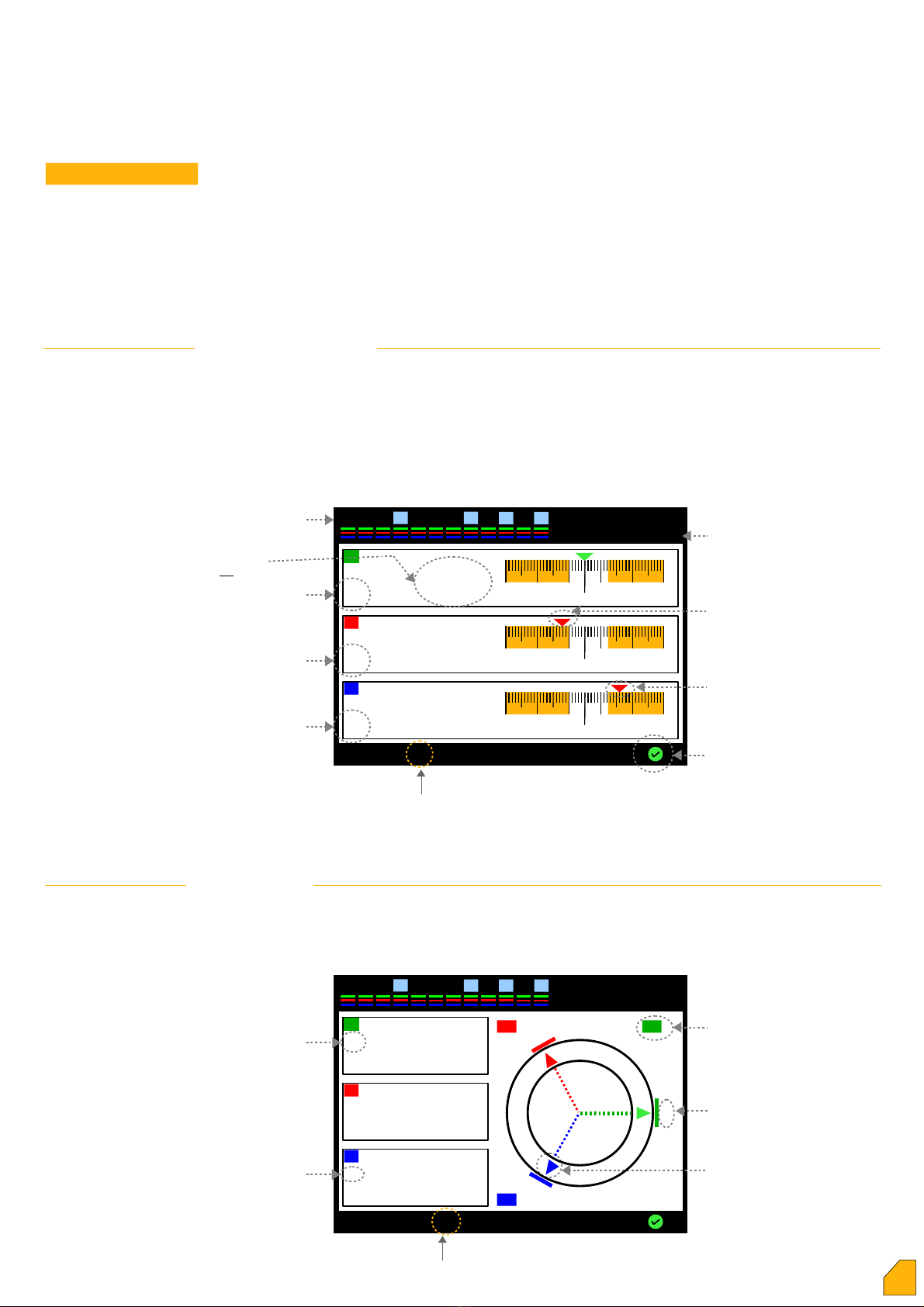
The device automatically switches to the
internalization of current polarity directions
mode. In this case, it is required to draw
enough current from each phase. If enough
current can not be drawn from any phase, the
device warns as “current flow directions not
detected” and shows the phase or phases
which are not internalized by ??? marks. When
the total of current polarity directions are
internalized, the device switches to the
automatic capacitor power internalization
mode.
.S.: There is no need to press on the main
screen key normally.
2. Step : Number of Steps
3. Step : Current Transformer Ratio
4. Step : Determine of Current Transformer
Directions
Device tries to identify capacitor powers and
the phases to which they connected, by
activating and then removing the steps in
sequence. It is recommended the closure of
variable loads in the system to ensure instant
internalization during this process. If required,
the user presses the “Make the steps
internalize” key and can make the system
internalize by himself. The automatic
internalization is put on hold in the meantime.
The step is not internalized automatically as
long as the user is in the “Make the steps
internalize” menu.
.S.1: There is no need to press on the main
screen key normally.
.S.2: Despite of the variable loads are
disabled, the connections of the device should
be checked again in case any power of the
steps and their connections are not intenalized
for a long time.
5. Step : Learning of step powers
For more info
When all the steps are internalized, the main
screen page comes up and the device starts
operating in automatic mode.
.S.1: It' s required to enter the Menu for the
parameters the user need to set-up. It' s
recommended to see the specifications of the
device by navigating in the menu.
.S.2: Unless the user disable the password
protection, some transactions (eg. set-up,
deleting the energy) will be password
protection.
6. Step (Main Screen)
5
1
Akım Po arite Yön eri Bu unamıyor
Ana Ekran
1 7 9 5 4
Current from M.V / Voltage from M.V (insulated)
Current from M.V / Voltage from L.V (non-insulated)
123456789 11
10 12
30
Menu %-Cos-PF-Σ Steps
.0
R
-50 -30 -10 10 30 50
cap. ind..
0
N+
%2
.0
S
-50 -30 -10 10 30 50
cap. ind.
0
N+
%9
.0
T
-50 -30 -10 10 30 50
cap. ind..
0
+
%5
.0
N
12345678910 11 12 30
Kvar
Make interna izeMain Screen
R S T
Detecting step powers... 10:00
P ease c ose the variab e oads in the system.
K1 -1.0 -1.0 -1.0
12345678910 11 12 30
Main MenuP ease wait
R
S
T
detected
detected
detected
T
S
searching for current
transformer directions ... 5
R
12345678910 11 12 30
Seaeching for current
transformer directions...
Main Menu
Current F ow dir. not Detected
R
S
T
????????
????????
????????
- Make sure a
phases have oads
- Check vo tage and
current inputs
!
1 2 3 4 5 6 7 8 9 10 11 12 30
searching for current
transformer directions ... 5
Main MenuP ease wait
R
S
T
????????
????????
????????
P ease commision
Load on each phase
12345678910 11 12 30
Enter current transformer ratio
seconds
30
00500 / 5A
App y▲ + ▼ - ◄
1 2 3 4 5 6 7 8 9 10 11 12 30
Insert current transformer ratio
seconds
20
CanceOkay Back
00500 / 5A
Save
Changes?
1 2 3 4 5 6 7 8 9 10 11 12 30
Enter number of step
seconds
20
12
App y▲ + ▼ - ◄
1 2 3 4 5 6 7 8 9 10 11 12 30
Enter number of step
seconds
20
18
CanceOkay Exit
Save
Changes?
Current from L.V / Voltage from L.V (insulated)
Current from L.V / Voltage from L.V (non-insulated)
1. Step : Number of Steps
When commissioning the first time,
measurement type must be selected ( 4 types).
The device waits for the user to select one of
these types. These are also described in detail
on pages 10 and 11.
se ect ▼ ▲
2 3 5 6 8 9 11 1274110 14 30

123456789 11
10 12
30
Menu %-Cos-PF-Σ Steps
.0
R
-50 -30 -10 10 30 50
kap. ind..
0
N+
%2
.0
S
-50 -30 -10 10 30 50
kap. ind.
0
O-
%9
.12
T
-50 -30 -10 10 30 50
kap. ind..
0
+
%5
.16
U
Main Screens
VARkombi-12- C-TFT-OG-SOLAR has color 3.2 "TFT screen. The switch between pages and
the key terms are provided on the bottom line of the display. The keys have different meanings in
different pages.
Steps, to which phase or phases they are connected, whether they are capacitors and/or
reactors, temperature value, whether the fan and the generator are activated or not, all these can
be observed on all main screens.
Temperature (ºC)
Of R phase
Q
Normal
%
% Over
consumption
Shows the system within the
normal limits
Steps
%
cos (cosΦ)
(Instant Consumptions)
Instant consumption % values of each phase and their scaled representation, the normal, under
and over compensation of the phases, their inductive-capacitive characterized loads and whether
the system is normal or not according to the accumulated energy can be observed on
consumptions page.
Instant cosΦ value of each phase, angular representation on triple-phase vector diagram, the
angle (Φ) values, the normal, under and over compensation condition of the phases, their
inductive-capacitive characterized loads and whether the system is normal or not according to the
accumulated energy can be observed on this page.
Every time pressing this key,
switches next to the right menu
123456789 11
10 12
30
Menu %-Cos-PF-Σ Steps
.0
R
N
+0
. 0
S
N
+
T
-
N
01
0
. 0
01
9
. 990
“ Φ “ angle on R phase
Current vector of T phase
Voltage point on R phase
Inductive
capacitive
R
1º0º
-1º
S
T
% Under
consumption
Over
Under
6

F ower Factor
The instant reactive power value (Q), active force values ( ), power factor values ( F) calculated
from their ratios (Q / ), vectoral representation of these forces, inductive - capacitive
characterized loads, whether the systems is normal or not as per the accumulated energy can be
monitored.
ΣRatios of Accumulated Energy
Accumulated energy ratios of each phase, total energy ratios and their scaled respresentation can
be monitored. This screen is very useful in terms of realizing the characters of loads connected to
the phases and enabling the user to take the necessary actions and make the corrections.
Whether the system is under penalty according to the total energy ratios can also be monitored.
Steps
This is the section used to see the conditions (activated-deactivated-holding)of steps more clearly,
to examine the reactive power of the system or for commissioning and disabling the steps
manually.
You must exit this menu for automatic mode as soon as you complete with
manual control. Otherwise, the device remains in manual control continuously.
123456789 11
10 12
30
Menu %-Cos-PF-Σ Steps
.0
RS T
.0
ind
cap
ind
cap
ind
cap
S T
Q1,763K
21,44K
F 0,991
- 0,155K
14,66K
- 0,999
- 1,454K
10,87K
- 0,990
Reactive powers
Active powers
ower factors
123456789 11
10 12
30
Menu %-Cos-PF-ΣSteps
.
R
N
%.
S
T
82
2.5
5
Cap.İnd.
0 0
1015202530
354045
50 5 10 15 20 25 30 35 40 45 50
N
%.53
%Normal
2.4
%Normal
3.8
%Normal
R
S
T
3.5
%Normal
3.3
%Normal
3.9
%Normal
Total capacitive % Total inducitive %
Capacitive % of R phase Inducitive % of R phase
Capacitive % of S phase Inducitive % of S phase
Capacitive % of T phase Inducitive % of T phase
2 3 5 6 8 9 11 12 30
Step
Status
Manua Mode
R
S
T
-0.346 KVAR
Exit VAR-W-VA
0.143 KVAR
0.345 KVAR
1
2
3
4
5
6
8
9
10
11
12
16
17
18
13
14
15
7
Switches to the section enabling the
commision and cut off the steps by
manual control.
74110
Can change the power
representation from
this menu
4,7,10,13,14. steps activated (greenl)
1,2,3,5,6,8,9. steps deactivated (white)
11 and 12. steps holding for decharge period (yellow)
2 3 5 6 8 9 11 12 30
Manual
Mode
on-off
R
S
T
-0.346 KVAR
Exit
0.143 KVAR
0.345 KVAR
1
2
3
4
5
6
8
9
10
11
12
16
17
18
13
14
15
7
74110
▲▼
7

2 3 5 6 8 9 11 12 30
Step info. 1
2
3
4
5
6
8
9
10
11
12
16
17
18
13
14
15
7
74110
Operation Time
34 hours
Number of switching
663 times
-1.000 KVar
R S T Tota power
Se ect ▼ Exit▲
Current
Voltage
2 3 5 6 8 9 11 12 30
74110 14
Exit◄ ► Setting
THD = 27.0 THD = 29.0 THD = 29.0
R S T
30
10
3
3 5 7 9 11 13 15 17 19 21 23 25 27 29 31T
1. MENU
This is the section in which many of the electrical measurements
are monitored and set-up are made. The parameters are
accessed by direction keys in the menu, parameters are inserted
by “Select” key and exit from the parameters by “Exit” key.
P.S.: Set-up section can only be accessed by password.
Harmonics
Displays the harmonic amplitude and %
values of voltage as well as current of three
phases up to 31.harmonic in terms of linear or
logarithmic on colour graphics screen. Total harmonic
column(for three phase)
R S T
Allows to switch between
the harmonics
The section in which;
- current or voltage,
- % or amplitude
- linear or logarithmic
selections of harmonics are made.
Amplitude or %
values of
harmonic
distortion
Step Monitoring
All steps can be accessed by up and down keys. Step
information of the step with red frame ( ) among the step
boxes is displayed on the left side of the screen while moving
with directon keys.
The information regarding the runtime of all steps, number of
switching, phase or phase to which they are connected, total
power values and whether they are capacitor or reactor can
all be accessed.
These values can be deleted when you make a change in
step. “Select” key is pressed for deleting on the related step.
Selecting the required type of deleting from the sub-screens
shown on the right side, operation can be realized.
Voltage, Current, Frequency
This is the section in which the current, voltage and frequency
drawn from the system are monitored.
ower
This is the section in which active, reactive and apparent
powers drawn from each phase and, total active, reactive and
apparent powers are monitored.
These values can be observed by selecting “ owers” or
“Total” at the bottom of the screen.
1 1
1 3
1 4
100
%f
A
A
A
V
Se ect ▼ Exit▲
1 1 MENU
►Harmonics
Step Monitoring
Voltage,Current,Frequency
ower
Energy
2 3 5 6 8 9 11 1274110 30
ExitAmp-Vo t %-Amp . Log-Lin
ExitDe ete a De ete ▲
CanceYes No
2 3 5 6 8 9 11 12 30
V
74110
RS T
Exit
219.8 219.2 220.2
A60.48 71.32 43.29
f49.9 Hz
2 3 5 6 8 9 11 12 30
Q
Var
74110
R
S
T
Exit
0.864 KVar
Tota
W
R
S
T33.17 KW
S
VA
R
S
T33.18 KVA
Powers Tota
8
1 2

Energy
This is the section in which the actice, reactive (ind. and cap.)
and apparent energies consumed one by one in each phase
and, the total active, reactive (ind. and cap.) and apparent
energy consumed in total of the system are monitored.
If required, “Reset” selection is pressed (eg.when the counter
is read for invoicing purpose). Entering the password, “Delete
counters ?” question appears on the screen. In case of
pressing “Yes”, all the counters are deleted.
.S.: assword process is described in this section.
Counter Index
The index value of electrical counter
connected to the plant is entered in
this section. Thus, the energies
recorded by electrical counter are
compared.
.S.: VARkombi-12- C-TFT-OG
does not use these values for
compensation.
ress “Setings” selection first
inorder to enter energy values.
Sub-screen will change and red
frame will appear on the index line.
Red frame is moved to the line of
which value will be entered by using
direction keys and, “Select” key is
pressed.
An underline in blue colour appears
in the line with red frame. The value
of number in the digit under which
the blue line is, is entered by using
up and down keys. Then, move to
the next digit by left key. When all
the digits are changed with the same
figures in the counter, “Apply” key is
pressed. When the values of all
lines are entered, “Okay” key is
pressed and, when “Save Changes”
appears on the screen, the data are
kept in the memory by pressing
“Okay” key.
Settings
This is the section in which you can find all set-up regarding
the device. assword is entered. After commissioning of
VARkombi-12- C-TFT-OG, any change of parameters is not
required normally. However, it may be necessary for the
users requring to create special conditions or ma e some
adjustments.
1 7
1 6
1 5
2 3 5 6 8 9 11 12 30
KWh
(Active)
74110
Exit
Σ-L1-L2-L3 Reset
KVARh
(ind.)
KVARh
(cap.)
KVAh
(apparent)
000003035 137
000000108 131
000000087 291
000003058 151
Total
Se ect ▼ ESC▲
1 7 SET-U
►
Target TanΦ - CosΦ
Switch On Time
Switch Off Time
Min. Step Time
2 3 5 6 8 9 11 1274110 30
1
2 3 5 6 8 9 11 12 30
KWh
(Active)
74110 14
ExitSettings
KVARh
(ind.)
KVARh
(cap.)
000000056 321
000000001 031
000000000 291
2 3 5 6 8 9 11 12 30
KWh
(Active)
74110
Cance
Yes
KVARh
(ind.)
KVARh
(cap.)
KVAh
(apparent)
000003035 137
000000108 131
000000087 291
000003058 151
Delete
Counters?
No
Counter Index
2 3 5 6 8 9 11 12 30
KWh
(Active)
74110
KVARh
(ind.)
KVARh
(cap.)
000000056 321
000000001 031
000000000 291
Counter Index
2 3 5 6 8 9 11 12 30
KWh
(Active)
74110
ExitSe ect
KVARh
(ind.)
KVARh
(cap.)
000000056 321
000000001 031
000000000 291
Counter Index
▼▲
App y▲ + ▼ - ◄
2 3 5 6 8 9 11 12 30
KWh
(Active)
74110
KVARh
(ind.)
KVARh
(cap.)
000000056 321
000000001 031
000000000 291
Counter Index
CanceOkay Exit
2 3 5 6 8 9 11 12 30
KWh
(Active)
74 10
KVARh
(ind.)
KVARh
(cap.)
000000056 321
000000001 031
000000000 291
Counter Index
CanceOkay Exit
Save
changes
1
1 7 9 7
Measurement Types
9

1 7 Settings – Measurement Type
1
The device offers the possibility of 4 types , according to the
connection.
Current Inputs
NL1
Vo tage Inputs
L2 L3
I3
I2
I1
L3
L2
L1
N
~
~
~
I3
k3
I2
k2
I1
k1
se ect ▼ exit▲
2 3 5 6 8 9 11 1274110
30
X/5A
X/5A
X/5A
MEDIUM VOLTAGE LOW VOLTAGE
Current from M.V / Voltage from L.V (without voltage transformer)
There are two settings
1) MV – LV Ratio : The ratio of medium voltage to the low voltage
value (phase to phase). Forexample ; 33.000V / 400V = 82,5
2) Transformer Type : DYN-11 or DYN-5
NOTE: The current transformer ratio must be entered in the section
from the menu 1.7.8
se ect ▼ exit▲
1 7 Measurement types
►MV – LV ratio
Transformer Type
2 3 5 6 8 9 11 1274110 30
1 1 Enter MV – LV ratio
2 3 5 6 8 9 11 1274110 30
app y▼ - ◄
0001.000
“Apply” key is pressed to take the target value into memory. “Save
Changes” message will appear on the screen. When “Okay” key is
pressed, the value is taken into the memory.
canceokay back
▲ +
Medium Voltage
(VOLT)
Low Voltage
(VOLT)
se ect ▼ exit▲
1 7
2 3 5 6 8 9 11 1274110 30
1 2 Enter Transformer Type
2 3 5 6 8 9 11 1274110 30
app y▼ -
DYN - 11
canceokay back
▲ +
DYN – 11
or
DYN – 5
Connection :
2A 2A 2A
10
►
MV – LV ratio
Transformer Type
Measurement types

L1 L2 L3
I3
I2
I1
L3
L2
L1
~
~
~
I3
k3
I2
k2
I1
k1
X/5A
X/5A
X/5A
se ect ▼ exit▲
2 3 5 6 8 9 11 1274110
30
Current from L.V / Voltage from L.V (with voltage transformer)
Current from M.V / Voltage from M.V (with voltage transformer)
NOTE: The current transformer ratio must be entered in the section
from the menu 1.7.8
Enter Voltage Trans. Value
2 3 5 6 8 9 11 1274110
30
app y▼ - ◄
0001.000
canceokay back
▲ +
Current Inputs
L1
Vo tage Inputs
L2 L3
I3
I2
I1
L3
L2
L1
~
~
~
I3
k3
I2
k2
I1
k1
X/5A
X/5A
X/5A
se ect ▼ exit▲
2 3 5 6 8 9 11 1274110
30
Connection: MEDIUM VOLTAGE LOW VOLTAGE
Voltage become isolated. The value of the voltage transformer must
be entered.
NOTE: The current transformer ratio must be entered in the section from the menu 1.7.8
Enter Voltage Trans. Value
2 3 5 6 8 9 11 1274110
30
app y▼ - ◄
0001.000
canceokay back
▲ +
2A2A2A
2A2A2A
11
MEDIUM VOLTAGE LOW VOLTAGE Connection:
Current Inputs Vo tage Inputs
L1 L2 L3
I3
I2
I1
L3
L2
L1
~
~
~
I3
k3
I2
k2
I1
k1
X/5A
X/5A
X/5A
N
N
se ect ▼ exit▲
2 3 5 6 8 9 11 1274110
30
Current from L.V / Voltage from L.V (without voltage transformer)
NOTE: The current
transformer ratio must
be entered in the
section from the menu
1.7.8
2A 2A 2A
MEDIUM VOLTAGE LOW VOLTAGE
Connection:
Current Inputs Vo tage Inputs

2 3 5 6 8 9 11 1274110 30
1 7 Settings – Switch on Time (decharge) (1 – 600 sec)
3
Enter Step Switch On (Dis.)
Time
2 3 5 6 8 9 1174110 30
App y▲ + ▼ - ◄
020 sec
CanceOkay Exit
This is the enterance section of the value of decharge period (sec) holded for preventing the
capacitor to activate again without decharging in the same step in case of requirement, after
release of the activated step. The value is setup to the required step starting from the digit under
which the blue line is, by using up and down keys. Then left key is pressed and the blue line
moves next to left digit. All the values are entered in the same way by using up and down keys.
ress “Apply” key inorder to take the period of step activating into memory. “Save changes”
message will appear on the screen. When “Okay” key is pressed, the value is taken into memory.
eriod of activating line is subjected to a function with the % value obtained from the ratio of
energies. In case % value is getting close to the inductive penalty line value, the time is reduced
automatically by the device. If necessasy, compensation speeds up; and if not, it slows down by
means of dynamic control of step activating, and continously do not make fast moves
unnecessarily.
.S.: Step activating time counts only for capacitor released newly. If necessary and a close
solution is found in another step, device activates the other option on time and the compensation
is not delayed.
If it' s not required the device to respond so quickly, holding period between the steps can be
extended to delay receiving process by increasing the value of ΔT on switching time described in
the next chapter.
.S.3:
In case of selecting the switch on
time less than min.step time,
device accepts the switch on time
as constant time value.
1 7 10 1
Other Relays : They proceed the step activating transaction with constant time adjusted. If the
time is not over, they will wait for the deadline. This causes delays in the compensation.
VARkombi-12- C-TFT-OG : It collects the energies (ind., cap., active) consumed. Step activating
and de-activating periods are decreased or increased automatically by the device according to the
consumed enerygy.
.S.: The energies consumed in VARkombi-12- C-TFT-OG and the % values are calculated
separately for each phase. Therefore, step activating and de-activating periods of each phase can
vary. For instance, while the step activating time for R-phase down to 2 seconds, the one for S-
phase can be 7 sec. VARkombi-12- C-TFT-OG analyze the system phase by phase and set-up
the compensation rate for each phase seperately.
The most simple explanation
regarding the ratio of energy
of step activating period has
been given below.
In fact the function consists of
much more complicated and an
array of fuzzy logic. Step sub-
period (min) determines the
lowest time value of level activating
time which can be reduced by the device.
This parameter can be specified by the user.
% ind.
Switch on time
0
Min. Switch Time
% ind.penalty line
t(sec)
12
Enter Step Switch On (Dis.)
Time
020 sn
Save
changes
1 7 Settings - Target TanΦ ( % ±75 ) – CosΦ ( ± 0,800 )
2
This is the section in which the required % value of the system is entered. CosΦ value
corresponding to the % value is displayed automatically on the other side. The value is setup to
the required step by using up and down keys starting from the digit where the blue line is. Then,
left key is pressed and the blue line moves next to left digit. All values are entered in the same
way by using the up and down keys. Moving the blue sub-line to the digit where the sign is by
using left key, the sign can be changed by pressing upwards key. (+) expresses inductive, (-)
expresses capacitive sections..
Enter target TanΦ value
2 3 5 6 8 9 11 1274110 30
App y▲ + ▼ - ◄
CosΦ
1.000
%+00
Enter target TanΦ value
2 3 5 6 8 9 11 1274110 30
CanceOkay Exit
CosΦ
1.000
%+00 Save
changes
“Apply” key is pressed to take the
target value into memory. “Save
Changes” message will appear on
the screen. When “Okay” key is
pressed, the value is taken into the
memory.

2 3 5 6 8 9 11 1274110 30
002 sn
1 7 Settings – Min. Switch Time (1 – 600 sec)
5
Enter Min.SwitchTime
2 3 5 6 8 9 11 1274110 30
App y▲ + ▼ - ◄
002
Save
changes
sec
CanceOkay Back
This is the section in which the value of step sub-period (min) is entered (sec). The value is setup
to the required step by using up and down keys starting from the digit where the blue line is. Then,
left key is pressed and the blue line moves next to left digit. All values are entered in the same
way by using the up and down keys.
ress “Apply” key inorder to take the step sub-period (min) time into memory. “Save changes”
message will appear on the screen. When “Okay” key is pressed, the value is taken into memory.
eriod of activating line is subjected to a function with the % value obtained from the ratio of
energies. It represents the minimum value of both step activating and de-activating time which can
be changed by the device.
Step sub-period is not taken into
account during fast mode.
2 3 5 6 8 9 11 1274110 30
020 sn
1 7 Settings – Switch Off time (1 – 600 sec)
4
Enter Step Switch Off Time
2 3 5 6 8 9 11 1274110 30
App y▲ + ▼ - ◄
020
Save
changes
sec
CanceOkay Back
This is the section in which the value of switch off time is entered (sec). The value is setup to the
required step by using up and down keys starting from the digit where the blue line is. Then, left
key is pressed and the blue line moves next to left digit. All values are entered in the same way by
using the up and down keys.
ress “Apply” key in order to take the switch off time into memory. “Save changes” message will
appear on the screen. When “Okay” key is pressed, the value is taken into memory.
eriod of activating line is subjected to a function with the % value obtained from the ratio of
energies. In case % value is getting close to the capactive penalty line value, the time is reduced
automatically by the device. If necessasy, compensation speeds up; and if not, it slows down by
means of dynamic control of switch off time, and continously do not make fast moves
unnecessarily.
.S.1: Switch off time counts only for capacitor activated newly. If necessary and a close solution
is found in another step, device deactivates the other option on time and the compensation is not
delayed.
If it' s not required the device to respond so quickly, holding period between the steps can be
extended to delay releasing process by increasing the value of ΔT off switching time described in
the next chapter.
.S.2: In case fast operating mode
is selected, switch off time of the
device is 200 msec.
It' s independent from switch off
time which is set-up.
.S.3: In case of selecting the
switch off time less than min.step
time, device accepts the switch off
time as constant time value.
1 7 10 2
Other Relays : They proceed the step de-activating transaction with constant time adjusted. If the
time is not over, they will wait for the deadline. This causes delays in the compensation.
VARkombi-12- C-TFT-OG : It collects the energies (ind., cap., active) consumed. Step activating
and de-activating periods are decreased or increased automatically by the device according to the
consumed enerygy.
.S.: The energies consumed in VARkombi-12- C-TFT-OG and the % values are calculated
separately for each phase. Therefore, step activating and de-activating periods of each phase can
vary. For instance, while the step de-activating time for R-phase down to 2 seconds, the one for
S-phase can be 7 sec. VARkombi-12- C-TFT-OG analyze the system phase by phase and set-
up the compensation rate for each phase seperately.
The most simple explanation
regarding the ratio of energy
of step de-activating period has
been given below.
In fact the function consists of
much more complicated and an
array of fuzzy logic. Level sub-
period (min) determines the
lowest time value of step de-activating
time which can be reduced by the device.
This parameter can be specified by the user.
% cap.
Switch Off time
0
Min. Step Time
% cap.penalty line value
t(sec)
13
200 msec Fast Mode
Normal Mode
Enter Step Switch Off Time
Enter Min.Switch Time

1 7 Settings – Inductive penalty limit ( % 3 – 50 )
6
This is the section in which the limit value of inductive/active % acceptable in compensation, is
entered. This value is determined by electric distribution company and is recommended to setup a
value slightly lower than requested to avoid penalty. The value is setup to the required step by
using up and down keys starting from the digit where the blue line is. Then, left key is pressed
and the blue line moves next to left digit. All values are entered in the same way by using the up
and down keys.
ress “Apply” key inorder to take the inductive penalty line into memory. “Save changes” message
will appear on the screen. When “Okay” key is pressed, the value is taken into memory.
Enter inductive penalty limit
2 3 5 6 8 9 11 1274110 30
App y▲ + ▼ - ◄
% 20
Enter inductive penalty limit
2 3 5 6 8 9 11 1274110 30
CanceOkay Exit
% 20 Save
changes
1 7 Settings – Capacitive penalty limit ( % 3 – 50 )
7
This is the section in which the limit value of capacitive/active % acceptable in compensation, is
entered. This value is determined by electric distribution company and is recommended to setup a
value slightly lower than requested to avoid penalty. The value is setup to the required step by
using up and down keys starting from the digit where the blue line is. Then, left key is pressed
and the blue line moves next to left digit. All values are entered in the same way by using the up
and down keys.
ress “Apply” key inorder to take the capacitive penalty line into memory. “Save changes”
message will appear on the screen. When “Okay” key is pressed, the value is taken into memory.
Enter cap.penalty limit
2 3 5 6 8 9 11 1274110 30
App y▲ + ▼ - ◄
% 10
Enter cap.penalty limit
2 3 5 6 8 9 11 1274110 30
CanceOkay Exit
%10 Save
changes
1 7 Settings – Current Transformer ( rimary) value ( 5.......10000 / 5A )
8
Enter current transformer value
2 3 5 6 8 9 11 1274110 30
App y▲ + ▼ - ◄
00500 / 5A
Enter current transformer value
2 3 5 6 8 9 11 1274110 30
CanceOkay Exit
This is the section in which the primary value of current transformers in compensation system, is
entered. The value is setup to the required step by using up and down keys starting from the digit
where the blue line is. Then, left key is pressed and the blue line moves next to left digit. All
values are entered in the same way by using the up and down keys. ress “Apply” key inorder to
take the current transformer (primary) value into memory. “Save changes” message will appear
on the screen. When “Okay” key is pressed, the value is taken into memory.
00500 / 5A
Save
changes
1 7 Settings – Number of Steps ( 3 – 12 )
9
Enter number of steps
2 3 5 6 8 9 11 1274110 30
App y▲ + ▼ - ◄
2 3 5 6 8 9 11 1274110 30
CanceOkay Exit
This is the section in which the number of steps will be used for compensation, is entered. The
value is setup to the required step by using up and down keys starting from the digit where the
blue line is. Then, left key is pressed and the blue line moves next to left digit. All values are
entered in the same way by using the up and down keys. ress “Apply” key inorder to take the
number of steps into memory. “Save changes” message will appear on the screen. When “Okay”
key is pressed, the value is taken into memory.
12 12 Save
changes
14
Enter number of steps

1 7 Settings – Advanced Setting Menu
10
This is the section in which the parameters are not used very often.
1 7 10
2 3 5 6 8 9 11 1274110 30
App y▲ + ▼ - ◄
0000
2 3 5 6 8 9 11 1274110 30
CanceOK ESC
Enter ΔT On Delay time Enter ΔT On Delay time
0000Save
changes
1
This is the section in which the holding time between steps during step activating, is entered. The
value is setup to the required step by using up and down keys starting from the digit where the
blue line is. Then, left key is pressed and the blue line moves next to left digit. All values are
entered in the same way by using the up and down keys. ress “Apply” key inorder to take ΔT on
switching time into memory. “Save changes” message will appear on the screen. When “OK” key
is pressed, the value is taken into memory.
In case at least one of ΔT on
or ΔT off time is setup to any
value rather than zero and the
device runs in quick mode, quick
mode is canceled automatically.
1 7 Settings – Advanced Setting Menu - ΔT off Delay Time (0 – 3600 sec)
10
2 3 5 6 8 9 11 1274110 30
App y▲ + ▼ - ◄
0000
2 3 5 6 8 9 11 1274110 30
CanceOkay Exit
Enter ΔT Off time Enter ΔT Off time
0000Save
changes
This is the section in which the holding time between steps during step de-activating, is entered.
The value is setup to the required step by using up and down keys starting from the digit where
the blue line is. Then, left key is pressed and the blue line moves next to left digit. All values are
entered in the same way by using the up and down keys. ress “Apply” key inorder to take ΔT off
switching time into memory. “Save changes” message will appear on the screen. When “Okay”
key is pressed, the value is taken into memory.
sec
sec
2
1 7 Settings - Advanced Setting Menu – current flow direction detection
10 3
This is the section in which the function of searching of current transformer polarity directions are
activated or de-activated. In case “Activated” is selected, internalization of current transformer
direction is always “On”, and only checks the directions when the device is powered. If “Off” is
selected, then the device internalize the current transformer directions at once and do not change
it. The “Off” choice should be selected for some loads (producing negative active load).
The required status for function is selected by using the up
and down keys. ress “Apply” key inorder to take this parameter
into memory. “Save changes” message will appear on the screen.
When “Okay” key is pressed, the value is taken into memory.
2 3 5 6 8 9 11 1274110 30
App y▲ + ▼ -
Enable
Direction Detection Status
Settings – Advanced Setting Menu - ΔT on Delay Time (0 – 3600 sec)
ΔT on
2
ΔT off
1 2
1
15
In case at least one of ΔT on
or ΔT off time is setup to any
value rather than zero and the
device runs in fast mode, quick
mode is canceled automatically.
In case internalization of direction is activated, internalization of
current transformer direction is always “On”, and only checks the
directions when the device is powered. In case the ends of
current are changed while the device is running, it can not detect
this. It' s needed to turn off and on again.

1 7 Settings – Advanced Setting Menu – Fast Step Mode
10 4
This is the section in which the fast step mode is enable or disable. In case “enable” is selected,
the device can activate many steps at the same time as well as de-activate them. If “Off” is
selected, then the device makes only one step attempt at each time.
The required status for function is selected by using the up
and down keys. ress “Apply” key in order to take this parameter
into memory. “Save changes” message will appear on the screen.
When “Okay” key is pressed, the value is taken into memory.
2 3 5 6 8 9 11 1274110 30
App y▲ + ▼ -
Enable
Fast Step Mode Status
In case fast step mode is activated, the device set ΔT on and
ΔT off times to zero automatically.
If fast step mode is selected, then the contactors which will be
used, must be absolutely compensation contactors, and the step
activating time (discharge) that the producers recommend, should
be entered.
1 7 Settings – Advanced Setting Menu – Step Parameters – Continuos Step ower Detecting
10 5
This is the section in which the continous internalization of step power is activated or de-activated.
In case “Activated” is selected, the device checks the step power at each step activating and de-
activating operation. In case of a change in power, then the device determine it and start to use
this value. If the last value of the capacitor is decreased by 50% than the power value of the initial
internalization, the device warns the user about the decrease in power of capacitor. It continues to
make compensation with the value internalized finally. In case “Off” is selected, the device can
only internalize the capacitor powers on the first
commissioning. It determines the change, but continues to
compensation with the values of initial internalization.
.S.: It can be necessary to disable the function of step power
İnternalization in some plants (especially, the plants in which the
loads are changing very quickly).
The required status for function is selected by using the up
and down keys. ress “Apply” key inorder to take this parameter
into memory. “Save changes” message will appear on the screen.
When “Okay” key is pressed, the value is taken into memory.
2 3 5 6 8 9 11 1274110 30
App y▲ + ▼ -
Enable
Contn. Step ower Detecting
1 7 Settings – Advanced Setting Menu – Step parameters – Constant Step Function
10 5
This is the section in which the constant step function is activated or de-activated.First step
switch on and stay at this position if this function is enable . This function is only used in activating
constant capacitor to meet the loss of transformers in the counters measure the medium voltage.
This capacitor must be connected ahead from the current transformers. Using the step of the
device for constant capacitor is not recommended actually. Much more steps are required for
compensation.
Consequently, constant capacitor can be connected to switch
input with a on-off switch. In case “Off” is selected, the device starts
to use this step.
The required status for function is selected by using the up
and down keys. ress “Apply” key inorder to take this parameter
into memory. “Save changes” message will appear on the screen.
When “Okay” key is pressed, the value is taken into memory.
2 3 5 6 8 9 11 1274110 30
App y▲ + ▼ -
Disable
Constant Step function
1 7 Settings – Advanced Setting Menu – Step Parameters – Step Sync.Time Sharing
10 5
This is the section of activating or de-activating the simultaneous use of levels in the same power.
In case “Activated” is selected, device tries to make the used hours of capacitors in the same
power equal.
The required status for function is selected by using the up
and down keys. ress “Apply” key inorder to take this parameter
into memory. “Save changes” message will appear on the screen.
When “Okay” key is pressed, the value is taken into memory.
2 3 5 6 8 9 11 1274110 30
App y▲ + ▼ -
Disable
Step Sync.Time Sharing
1
2
3
16

1 7 Settings – Advanced Setting Menu – Step Parameters – Enter Step owers
10 5
This is the section in which the step powers are entered. The
device directs the user with subcommand display
continuously. It is moved on the step of which the power is
required to be entered by using the up and down keys. In the
meantime, that line are in red colour. Select key is pressed.
The selected step number comes to screen. The selection of
triple-phase or single-phase of capacitor or reactor should be
made on this screen.
The position of red frame changes when up and down keys
are used. In case the reactive load on the step is triple-phase,
the frame is moved on triple-phase and “Select” key is
pressed. Triple-phase option becomes red in this case. If up or
down direction key is pressed, the red frame moves to total
value digit. The “Select” key is pressed and a blue underline
appears on the last digit inside of the frame. The value is
setup by using the up and down keys starting from the digit
where the blue line is. Then, left key is pressed and the blue
underline moves next to the left digit. All the values are
entered in the same way by using up and down keys. The
“Apply” key is pressed to take them into memory. The sub-
command screen changes and “Okay”, then “Exit” key is
pressed. “Save Changes” will appear on the screen. When
“Okay” key is pressed, the value is taken into memory.
If the reactive load on the step is single-phase, frame is
moved onto single-phase and “Select” key is pressed. Single-
phase option becomes red in this case. In case of pressing up
or down direction key is pressed, the red frame moves on the
lines of R, S and T-phases including total value. In case of
which phase the reactive load on the step is connected to,
“Select” key is pressed during on that line. Entering the value
and taking it into memory is the same as described above.
.S.: Moving the blue underline to the digit on which the sign is
by using the left key, the sign can be changed by pressing
upwards key. (+) represents the reactor, (-) represents the
capacitor.
2 3 5 6 8 9 11 1274110 30
Exit▲▼
Kvar
4
Se ect
R S T
K1 --------- --------- ---------
K2 --------- --------- ---------
K3 --------- --------- ---------
K4 --------- --------- ---------
K5 --------- --------- ---------
Step powers are adjusted manually...
2 3 5 6 8 9 11 1274110 14 30
Exit▲▼
3-phase
Se ect
R
S
T
1.Step
1-phase
Σ
0.000 KVAr
0.000 KVAr
0.000 KVAr
0.000 KVAr
2 3 5 6 8 9 11 1274110 30
3-phase
R
S
T
1.Step
1-phase
Σ
0.000 KVAr
0.000 KVAr
0.000 KVAr
0.000 KVAr
App y▲ + ▼ - ◄
CanceOkay Exit
Exit▲▼Se ect
2 3 5 6 8 9 11 1274110 30
3-phase
R
S
T
1.Step
1-phase
Σ
0.000 KVAr
0.000 KVAr
0.000 KVAr
0.000 KVAr
CanceOkay Exit
Save
changes
1 7 Settings – Advanced Setting Menu – Step Parameters – Delete Step owers
10 5
2 3 5 6 8 9 11 1274110 30
Exit▼
Kvar
5
De ete
RST
K1 -0,500 -0,500 -0,500
K2 -1,000 -1,000 -1,000
K3 -1,500 -1,500 -1,500
K4 -2,500 -2,500 -2,500
K5 -3,330 -3,330 -3,330
2 3 5 6 8 9 11 1274110 30
Kvar R S T
K1 -0,500 -0,500 -0,500
K2 -1,000 -1,000 -1,000
K3 -1,500 -1,500 -1,500
K4 -2,500 -2,500 -2,500
K5 -3,330 -3,330 -3,330
2 3 5 6 8 9 11 1274110 30
Kvar R S T
K1 -0,500 -0,500 -0,500
K2 -1,000 -1,000 -1,000
K3 -1,500 -1,500 -1,500
K4 -2,500 -2,500 -2,500
K5 -3,330 -3,330 -3,330
2 3 5 6 8 9 11 1274110 30
Kvar RST
K1 -0,500 -0,500 -0,500
K2 -1,000 -1,000 -1,000
K3 -1,500 -1,500 -1,500
K4 --------- --------- ---------
K5 -3,330 -3,330 -3,330
2 3 5 6 8 9 11 1274110 30
Kvar RST
K1 --------- --------- ---------
K2 --------- --------- ---------
K3 --------- --------- ---------
K4 --------- --------- ---------
K5 --------- --------- ---------
CanceOkay ExitCanceOkay Exit
Step
Delete ?
Step
Delete ?
Exit▼ De ete De ete AExit▼ De ete De ete A
This is the section in which the step parameters are deleted
one by one, or all. In case the reactive load is changed in any
step, the power of that step must be deleted to let the device
internalize the the power of new step. The device fowards the
user continuously by sub-command screen. Moving onto the
step of which power required to be deleted, the up or down
key is pressed. The line is in red colour in the meantime. In
case of deleting only that step, “Delete” key is pressed; in case
of deleting all steps (if a device used in somewhere
else is connected to a new plant),
“Delete All” key is pressed.
If “Delete” key is pressed, “Step Delete?”
warning appears on the screen. When
“Okay” key is pressed, the power of
that step would be deleted. The device
will automatically try to internalize the
power of that step again. You can exit
the menu by “Exit” key. In case “Delete
All?” key is pressed, “Steps Delete?”
warning appears on the screen. When
“Okay” key is pressed, the power of all
steps would be deleted. The device
will automatically try to internalize the
power of that step again. You can exit
the menu by “Exit” key.
17
De ete A
Table of contents
Other KAEL Muhendislik Elektronik Relay manuals
Popular Relay manuals by other brands

Datakom
Datakom DPR-02 installation manual

ABB
ABB Relion 615 series Quick installation guide

Woodward
Woodward highprotec MRI4 user manual

ASO Safety Solutions
ASO Safety Solutions ELMON 34-32 operating manual

Siemens
Siemens 3VU2932-4 Series Assembly instructions

MÜLLER + ZIEGLER
MÜLLER + ZIEGLER GMAT-2 quick start guide