KAESER SIGMA CONTROL BUB 82 Series User manual

Service manual
Controller
SIGMA CONTROL BUB 82.XX
7_7000_0 11USE

/KKW/SSC 1.01 en 01 BA-SIGMA CONTROL

Quick user guide
Controller
SIGMA CONTROL BUB 82.XX
7_7000_0 11 USE


1. Important settings ............................................................................................................. 1
2. Changing the display language ........................................................................................ 2
3. Entering and displaying passwords .................................................................................. 3
4. Adjusting the system setpoint pressure ........................................................................... 4
5. Activating the «clock» key ................................................................................................ 5
6. Activating the «remote control» key ................................................................................. 6
7. Changing the control mode .............................................................................................. 7
8. Outputting important operational states of the machine ................................................... 8
9. Resetting maintenance interval counters ......................................................................... 9
10. Displaying messages ....................................................................................................... 10
11. Pressure relief valve checking ......................................................................................... 11
12. Checking the temperature sensor and overheating shutdown function ........................... 13
Contents
7_7000_0 11 USE
Quick user guide Controller
SIGMA CONTROL BUB 82.XX i

Contents
ii Quick user guide Controller
SIGMA CONTROL BUB 82.XX 7_7000_0 11 USE

1 Important settings
In this chapter, important or often used settings are explained in brief. Detailed information on function,
configuration, fault removal and important instructions concerning safe operation are found in sub‐
sequent chapters.
Setting and other work on the machine may only be carried out by the following persons:
■ persons trained on the machine/controller and persons instructed by and under the super‐
vision of a specialist,
■ trained technicians,
■ authorized service personnel.
1 Important settings
7_7000_0 11 USE
Quick user guide Controller
SIGMA CONTROL BUB 82.XX 1

2 Changing the display language
1. In the main menu, press the «UP» key until the current language appears.
8 8 p s i g 1 7 6 ° F
→ D e u t s c h ↲ Current language
– – – – – – – – – –
2. Press «Enter».
3. Keep on pressing the «DOWN» or «UP» key until the required language appears.
4. Press «Enter» to accept the language.
The language is now set.
5. Press the «Escape» key as often as necessary to return to the main menu.
2 Changing the display language
2Quick user guide Controller
SIGMA CONTROL BUB 82.XX 7_7000_0 11 USE

3 Entering and displaying passwords
The following passwords have been entered in the controller at the factory:
Level 0 Level 4
password 00000 12EXP
Tab. 1 Passwords
1. In the main menu, keep pressing the «UP» key until
password
appears in the third line of the
display.
2. Press «Enter».
8 8 p s i g 1 7 6 ° F
p a s s w o r d
X X X X X L 0 ↲
X X X X X L 0 Current level
3. Press «Enter».
An inverse cursor appears.
4. Keep on pressing the «DOWN»or «UP» key until the required character appears.
5. Press «Enter».
The cursor jumps to the next password character.
6. Set the remaining characters of the password until it is complete.
After entering the last character the activated password level is displayed.
7. Press the «Escape» key as often as necessary to return to the main menu.
3 Entering and displaying passwords
7_7000_0 11 USE
Quick user guide Controller
SIGMA CONTROL BUB 82.XX 3

4 Adjusting the system setpoint pressure
The information relates to settings for a compressor. Vacuum pumps or other devices should be
treated accordingly.
Precondition Password level 4 is activated.
Select menu configuration > press. settings.
1. In the main menu, keep pressing the «UP» key until
configuration
appears in the third line of
the display.
2. Press «Enter».
press. settings
appears in the display.
3. Press «Enter».
compressor
appears in the display.
4. Press «Enter».
8 8 p s i g 1 7 6 ° F
s e t p o i n t p r e s s .
p 1 S P : 8 0 p s i g Current system setpoint pressure p1 (example)
S D : – 7 . 3 p s i g Current switching differential p1 (example)
Setting system setpoint pressure and switching differential for p1
1. Press «Enter» to adjust the value for setpoint p1.
An inverse cursor appears.
2. Adjust the value with the «UP» or «DOWN» key.
3. Press the «Enter» key to accept the value.
4. Press the «DOWN» key once.
8 8 p s i g 1 7 6 ° F
p 1 S P : 8 8 p s i g Changed system pressure setpoint
S D : – 7 . 3 p s i g Current switching differential p1
p 2 S P : 1 0 4 p s i g Current system setpoint pressure p2
5. Press «Enter» to adjust the value for switching differential p1.
An inverse cursor appears.
6. Adjust the value with the «UP» or «DOWN» key.
7. Press the «Enter» key to accept the value.
8. If necessary, adjust the value for p2 in the same way.
Further information See chapter 7.3 for all machine pressure parameters and their adjustment.
4 Adjusting the system setpoint pressure
4Quick user guide Controller
SIGMA CONTROL BUB 82.XX 7_7000_0 11 USE

5 Activating the «clock» key
Precondition Password level 4 is activated.
Select the clock menu
1. From the main menu, keep pressing the «UP» key until
clock
appears in the third line of the
display.
2. Press «Enter».
8 8 p s i g 1 7 6 °
c l o c k k e y : n
r e s e t : n
– – – – – – – – – –
Activating the clock key
1. Press the «UP» key once.
8 8 p s i g 1 7 6 °
c l o c k k e y : n
r e s e t : n
2. Press «Enter».
An inverse cursor appears.
3. Press the «UP» key once.
The display changes to
clock key: y
.
4. Press «Enter».
The «clock» key is activated and can be used.
The «clock» key can be deactivated in the same way.
Further information See chapter 7.4 for configuration of starting and stopping the machine.
See chapter 7.6.2 for configuration of load changeover based on a clock program.
5 Activating the «clock» key
7_7000_0 11 USE
Quick user guide Controller
SIGMA CONTROL BUB 82.XX 5

6 Activating the «remote control» key
Further settings have to be made to allow the machine to be remotely controlled.
➤ Refer to further information in this chapter.
The «remote control» key can be activated in two menus:
< compressorstart >
or
< load control >
.
Precondition Password level 4 is activated.
Select configuration.
1. From the main menu, keep pressing the «UP» key until
configuration
appears in the third line
of the display.
2. Press «Enter».
press. settings
appears in the display.
Activating the «remote control» key in the compressor start menu
1. Keep pressing the «DOWN» key until
compressorstart
appears in the third line of the display.
2. Press «Enter».
compressor ON
appears in the third line of the display.
3. Press «Enter».
4. Keep pressing the «DOWN» key until
remote key: n
appears in the second line of the display.
5. Press «Enter».
An inverse cursor appears.
6. Press the «UP» key.
The display changes to
remote key: y
.
7. Confirm the setting with «Enter».
The «remote control» key is activated and can be used.
8. Press the «remote control» key to enable remote mode.
The «remote control» key can be deactivated in the same way.
Activating the «remote control» key in the load control menu
1. Keep pressing the «DOWN» key until
load control
appears in the second line of the display.
2. Press «Enter».
3. Keep pressing the «UP» or «DOWN» key until
remote mode y/n
appears in the third line of the
display.
4. Press «Enter».
An inverse cursor appears.
5. Select the value
y
with the «UP» or «DOWN» key and confirm with «Enter».
The «remote control» key is activated and can be used.
The «remote control» key can be deactivated in the same way.
Further information See chapter 7.4 for configuration of machine starting and stopping.
See chapter 7.7 for configuration of load changeover under master control.
6 Activating the «remote control» key
6Quick user guide Controller
SIGMA CONTROL BUB 82.XX 7_7000_0 11 USE

7 Changing the control mode
Select menu configuration > control mode
Precondition Password level 4 is activated.
1. From the main menu, keep pressing the «UP» key until
configuration
appears in the third line
of the display.
2. Press «Enter».
press. settings
appears in the display.
3. Press the «DOWN» key once, then «Enter» to select
< control mode >
.
4. Press «Enter».
8 8 p s i g 1 7 6 °
l o c a l m o d e
→ Q u a d r o Current control mode
c o n t r o l m o d e
Changing the control mode
1. Select the control mode with the «UP»or «DOWN» key.
2. Press «Enter» to accept the control mode.
3. Press the «Escape» key as often as necessary to return to the main menu.
Further information See chapter 4.8 for the functions of the control modes.
See chapter 7.5 for configuring the parameters of the control modes.
See chapter 8.15 to determine the optimum control mode.
7 Changing the control mode
7_7000_0 11 USE
Quick user guide Controller
SIGMA CONTROL BUB 82.XX 7

8 Outputting important operational states of the ma‐
chine
Important operational machine states can be assigned via floating relay contacts as a binary signal
on the outputs DO0.3 – DO0.5. Further outputs are optionally available. Each output can be assigned
only once.
Precondition Password level 4 is activated.
Select configuration > I/O periphery > DO functions.
1. From the main menu, keep pressing the «UP» key until
configuration
appears in the third line
of the display.
2. Press «Enter».
press. settings
appears in the display.
3. Press the «DOWN» key until
I/O periphery
appears.
4. Press «Enter» twice to select
< DO functions >
.
8 8 p s i g 1 7 6 °
c o n t r o l l e r O N Controller ON message
→ n . a . ↲ No output assigned
g r o u p a l a r m Group alarm message
Assigning a message to an output
1. Select the required message with the «UP»or «DOWN» key.
2. Press «Enter».
An inverse cursor appears.
3. Use the «UP»or «DOWN» key to select a spare output and confirm with «Enter».
A message is now sent via the output assigned.
4. Press the «Escape» key as often as necessary to return to the main menu.
Further information See chapter 7.10 for configuration and use of the controller's inputs and outputs.
8 Outputting important operational states of the machine
8Quick user guide Controller
SIGMA CONTROL BUB 82.XX 7_7000_0 11 USE

9 Resetting maintenance interval counters
Precondition Maintenance carried out,
warning message acknowledged,
password level 4 activated.
Select menu maintenance > maintenance interval counter
1. From the main menu, keep pressing the «DOWN» key until
maintenance
appears in the third
line of the display.
2. Press «Enter».
3. The maintenance interval hours are shown:
8 8 p s i g 1 7 6 °
o i l f i l t e r
6 0 0 0 h | 0 1 5 0 h ↲
r e s e t : n
4. Keep pressing the «UP» or «DOWN» key until the component indication appears in the second
line of the display.
Resetting maintenance interval counters
1. Press the «DOWN» key.
2. Press «Enter».
An inverse cursor appears.
3. Use the «UP» key to select the value
y
and confirm with «Enter».
The remaining interval hours now changes to the default interval and the reset display changes
from
y
to
n
.
4. Press the «Escape» key as often as necessary to return to the main menu.
Further information See chapter 8.11 for setting the maintenance intervals.
See chapter 10 for the maintenance of the controller.
9 Resetting maintenance interval counters
7_7000_0 11 USE
Quick user guide Controller
SIGMA CONTROL BUB 82.XX 9

10 Displaying messages
Selecting menu status > messages
1. From the main menu, keep pressing the «DOWN» key until
status
appears in the third line of
the display.
2. Press «Enter».
messages
appears in the display.
3. Press «Enter».
event info
appears in the display.
Displaying event information
1. Press «Enter».
The last message (event) displayed appears again in the display. The messages are displayed
chronologically in the order in which they occur.
2. Scroll through past events with the «DOWN» key and back to the current message with
the «UP» key.
3. Press the «Escape» key as often as necessary to return to the main menu.
Displaying the last alarm
Precondition Menu option
< status > messages >
is selected.
1. Keep pressing the «DOWN» key until
last alarm
appears in the second line of the display.
2. Press «Enter».
The last alarm message is displayed.
3. Press the «Escape» key as often as necessary to return to the main menu.
Displaying the last warning
Precondition Menu option
< status > messages >
is selected.
1. Keep pressing the «DOWN» key until
last warning
appears in the second line of the display.
2. Press «Enter».
The last warning message is displayed.
3. Press the «Escape» key as often as necessary to return to the main menu.
Displaying the number of current alarms or warnings
Precondition Menu option
< status > messages >
is selected.
1. Keep on pressing the «DOWN» key until number of current alarms and warnings appears.
2. Press the «Escape» key as often as necessary to return to the main menu.
Further information See chapter 8.2 to acknowledge alarm and warning messages.
10 Displaying messages
10 Quick user guide Controller
SIGMA CONTROL BUB 82.XX 7_7000_0 11 USE

11 Pressure relief valve checking
Overview
■ Preparation for the test
■ Carrying out the check
■ Correct conclusion of the test
When the check mode is activated, monitoring of internal pressure (blowoff protection - if pro‐
vided) and regulation of network pressure are deactivated.
Depending on available measured values, the internal pressure pi or system pressure pN are
used for the check.
The measured value of internal pressure pi is used to describe the following check.
CAUTION
Danger of injury from pressurized components
➤ The instructions listed below must be followed without fail.
Preparation for the test
1. Note the opening pressure (or activating pressure) of the pressure relief valve from the machine's
nameplate.
2. Press the «OFF» key to shut down the machine.
3. Close the user's shut-off valve between the machine and the air distribution network.
4. Activate password level 4 in the controller (see section 7.2.3).
5. From the main menu, keep pressing the «UP» key until
machine test
appears in the third line
of the display.
6. Press «Enter».
TÜV check
appears in the display.
7. Press «Enter».
8 8 p s i g 1 7 6 °
T Ü V c h e c k
r e l i e f v a l v e : n
p R V : 2 3 2 p s i g activating pressure of pressure relief valve (example)
8. Press «Enter».
An inverse cursor appears.
Carrying out the check
1. Use the «UP» key to select the value
y
and confirm with «Enter».
The check mode is now activated. Monitoring of internal pressure and system setpoint pressure
is deactivated.
2. Press the «DOWN» key once to display the internal pressure
8 8 p s i g 1 7 6 °
r e l i e f v a l v e : y
p R V : 2 3 2 p s i g activating pressure of the pressure relief valve
p i : 3 6 p s i g actual internal pressure
11 Pressure relief valve checking
7_7000_0 11 USE
Quick user guide Controller
SIGMA CONTROL BUB 82.XX 11

3. Press and hold the «ON» key.
The machine switches to load, the machine's internal pressure pi rises.
4. Observe the displayed pressure rise pi during the check.
5. If the pressure pi increases to more than 10 % above the correct opening pressure of the pressure
relief valve, shut down the machine with the «OFF» key and change the valve.
If the alarm message
pRV ⇞
appears, the pressure relief valve is defective. The permissible
internal pressure was exceeded by 29 psi.
➤ Have the pressure relief valve replaced by an authorized KAESER Service Technician.
Avoid oil mist:
➤ Release the «ON» key as soon as the pressure relief valve opens to minimize oil mist blow
off.
Correct conclusion of the test
1. Press the «UP» key once.
2. Press «Enter».
An inverse cursor appears.
3. Use the «DOWN» key to set the value
n
and confirm with «Enter».
The "pressure relief valve" check mode is de-activated and the test ended.
4. Press the «Escape» key as often as necessary to return to the main menu.
5. Open the shut-off valve from the machine again.
Result The machine is ready for operation.
Further information See chapter8.13 to test the pressure relief valve.
11 Pressure relief valve checking
12 Quick user guide Controller
SIGMA CONTROL BUB 82.XX 7_7000_0 11 USE

12 Checking the temperature sensor and overheating
shutdown function
The machine should shut down if the airend discharge temperature (ADT) reaches 230 °F. A higher
temperature is simulated to check this function. For this, it is necessary to determine and enter an
offset value.
During the check mode, this offset value is added to the actual airend discharge temperature to cause
the machine to shut down prematurely.
Overview
■ Ascertain and enter the offset
■ Shut down the machine and allow to cool down slightly
■ Carrying out the check
■ Correct conclusion of the test
Ascertaining offset
1. Read off the airend discharge temperature under load (normal working temperature)
(first line of the display, e.g.: 176 °F)
2. Calculate offset:
Offset = 230 °F − indicated airend discharge temperature
(e.g.: Offset = 54 °F at 176 °F airend discharge temperature)
3. Shut down the machine with the «OFF» key
4. Watch the first line of the display and wait until the airend discharge temperature has dropped by
about 9 °F.
Setting the offset
1. Activate password level 4 in the controller (see section 7.2.3).
2. From the main menu, keep pressing the «UP» key until
machine test
appears in the third line
of the display.
3. Press «Enter».
TÜV check
appears in the display.
4. Press «Enter».
5. Keep pressing the «DOWN» key until the following is displayed:
8 8 p s i g 1 7 6 °
A D T - a l a r m : n
o f f s e t : 1 0 4 ° F offset value setpoint (example)
A D T ⇞ : 3 2 ° F
6. Press «Enter».
An inverse cursor appears.
7. Use the «DOWN» key or the «UP» key to enter the calculated offset and confirm by pressing
«Enter».
Carrying out the check
Precondition Machine cooled down by approx. 9 °F
12 Checking the temperature sensor and overheating shutdown
function
7_7000_0 11 USE
Quick user guide Controller
SIGMA CONTROL BUB 82.XX 13

1. In the main menu, keep pressing the «UP» key until
ADT alarm: n
appears in the third line of
the display.
2. Press «Enter».
An inverse cursor appears.
3. Use the «UP» key to select the value y and confirm with «Enter».
The check mode is now activated.
4. Press the «DOWN» key once to display the airend discharge temperature + offset:
8 8 p s i g 1 6 3 ° Fallen airend discharge temperature (163 °F)
A D T - a l a r m : y Overheating shutdown
o f f s e t : 8 6 ° F offset value setpoint (example)
A D T ⇞ : 2 1 7 ° F Airend discharge temperature + offset
5. Press the «ON» key to switch the machine to LOAD.
The machine switches to LOAD and the airend discharge temperature rises again.
As soon as a value ADT of 230 °F is reached, the machine shuts down and an alarm is activated.
The machine does not shut down?
➤ Abort the test and contact KAESER Service as soon as possible.
Correct conclusion of the test
1. Press «Enter».
2. Reset the offset to 104 °F and confirm with «Enter».
3. In the main menu, keep pressing the «UP» key until
ADT alarm: y
appears in the third line of
the display.
4. Press «Enter».
5. Use the «UP» key to select the value n and confirm with «Enter».
The "overheating shutdown" check mode is de-activated and the test ended.
6. Press the «Escape» key as often as necessary to return to the main menu.
Further information See chapter8.14 for testing the temperature sensor.
12 Checking the temperature sensor and overheating shutdown
function
14 Quick user guide Controller
SIGMA CONTROL BUB 82.XX 7_7000_0 11 USE
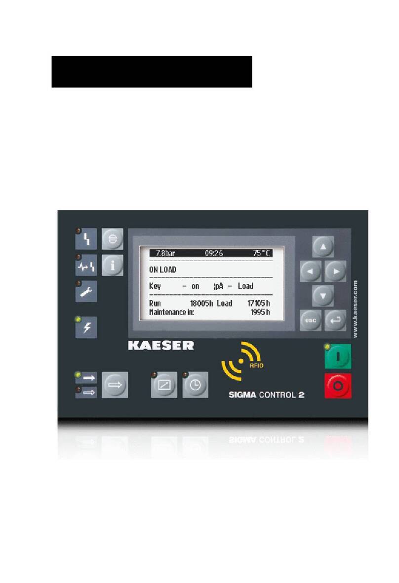
Table of contents
Other KAESER Controllers manuals
Popular Controllers manuals by other brands

Emerson
Emerson EZH Series instruction manual

2VV
2VV AirGENIO Assembly, installation and operation instructions

Pololu
Pololu Mini Maestro Series Getting started

Gonnheimer Elektronic
Gonnheimer Elektronic DC 155 manual

Danfoss
Danfoss AMD 610 AS installation guide

Nexmosphere
Nexmosphere XN-180 quick start guide