2VV AirGENIO Owner's manual

Installation and operation instructions
EN
AirGENIO
BASIC EC controller


42 V V. Creating innovative solutions for you and your business since 1995.
ABOUT THE MANUAL
Symbol Meaning
WARNING – these symbols warn about factors that may cause serious injury to the user or damage to the device. They
also draw attention to important instructions, properties, procedures or measures that must be taken into account or
abided by during operation and maintenance.
ATTENTION – this symbol draws attention to an important activity or information that must be taken into account, but one
that will not endanger health or damage the device.
INFORMATION – this symbol draws attention to useful information about the device
This manual was written to provide necessary information about the AirGENIO BASIC EC controller concerning its oper-
ation, maintenance and service. Authorized persons must be thoroughly familiar with the contents of the manual before
beginning any work with the device.
Declaration of conformity
The product has been designed, produced an marketed in compliance with all the applicable provisions, and abides to the
provisions of the European Parliament and Council, including the amendments under which it has been classied. It is safe
under normal conditions and under the conditions laid down by the manual. The assessment was conducted pursuant to
harmonized European standards included in the relevant EC Declaration of Conformity. The current and full version of the
EC Declaration of Conformity can be found at www.2vv.cz
IMPORTANT WARNINGS
▪Read this manual carefully.
▪Proceed exactly according to the instructions stated here in order to install controller properly and safely.
▪Do not put the device into operation unless you are thoroughly acquainted with all the instructions, warnings and
recommendations.
▪Illustrations used in this manual may not always correspond to reality; their purpose is to help in understanding the
installation steps. Texts, drawings, photos and other elements used here are, however, protected by copyright. Their
abuse or unauthorised copying is a punishable offence.
▪The manual must be considered an integral and inseparable part of the controller. Store it for future use and pass it
on to any future owners.
▪Avoid contacts with energised electrical parts; always treat the product as if it is live. Always disconnect the power
supply before connecting, servicing or repairing the product
▪Always verify that you apply appropriate power supply to the product and use appropriate wire size and characteris-
tics. Make sure that all the screws are well tightened.
MANUFACTURER’S CONTACT INFORMATION
Unexpected situations may occur in practice that could not be included and described in this manual. When in doubt about how to
proceed, contact the manufacturer:
2VV, s.r.o.
Fáblovka 568,
533 52 Pardubice,
Czech Republic
T: +420 466 741 811
E: 2vv@2vv.cz
W: www.2vv.cz
DELIVERY AND UNPACKING
PACKAGING AND CONTENTS OF THE DELIVERY
The controller is supplied as a single, complete whole, packaged to protect it against damage. The controller is transported in a card-
board box to protect the device from damage.
The delivery includes the following:
▪Transport packaging
▪Controller (1×)
▪Instructions for Quick Installation and Safe Use of controller

5
2 V V. Creating innovative solutions for you and your business since 1995.
Check immediately after unpacking:
- if the package is damaged
If it is damaged, contact the carrier company. If the complaint is submitted too late, it may not be accepted.
- if you received the controller type you ordered
Ifyoundanydefectsordiscrepancies,donotunpackthecontrollerandimmediatelyinformthesupplier.Ifyoudonot
submit your complaint on time, future complaints will not be accepted.
HANDLING THE DELIVERY
Itisrecommendedthatthedeviceandloadisonlyhandledbypersonswithcorrespondingqualications.
Transport the delivery carefully to the place where it will be unpacked or stored.
STORAGE BEFORE UNPACKING
If you do not intend to unpack and install the controller immediately after delivery, store it in the following conditions:
▪Store the controller in original packaging in a dry area protected against weather conditions that could damage the packaging and
negatively affect the condition of the device. The ambient temperature must be between +5 °C and +40 °C.
▪Do not remove the controller from the box.
DEVICE DESCRIPTION
INTRODUCTION
AirGENIO BASIC EC controller is designed to control the air curtains and heating units with electric or water coils, using manual heating
control and manual stepless fan speed control. Controller allows to connect up to two external switches (one to affecting the heat and
one to affecting the fan speed)
Ambient version of controller doesn´t allows to control heating and doesn´t support connection of room thermostat.
CONTROLLER IDENTIFICATION
1 – Code for AirGENIO BASIC EC controller
2 – Master controller
3– for EC fans only
4– Heater type:
E2 = BASIC EC with electric
V1 = BASIC EC with water heater control
S0 = BASIC EC without heater control
BASIC EC ambient
AGBA1-M-ECx-xx-S0
BASIC EC heater
AGBA1-M-ECx-xx-E2 (V1)
DIMENSIONS
116,5
80,5
51,3
ZOBRAZENO BEZ SAMOLEPKY A TOČÍTKA
POZ
NÁZEV
ČÍSLO
MN
MJ
MJ IFS
1
K-CP-MC-HX-01-4P
3-021-D14809
1
ks
kg
2
DUT-P-AL-1,0-ZLUTA
4-101-0330
3
ks ks
3
PR-K-V-ON-OFF
4-101-0334
1
ks ks
4
E-OVL-SM-EC-102X66-50-22-VL 3-020-D20636
1
ks
m2
5
PL-V-B-DNO-NEW
4-114-0036
1
ks ks
6
PL-V-BR-TOC-B
4-114-0037
1
ks ks
7
PL-V-B-TELO-NEW
4-114-0039
1
ks ks
8
PL-V-B-VIKO-GOTTAK
4-114-0040
1
ks ks
9
KRKL-CP-VC | Krabice kl., 3VVL BH Fc 23
4-117-0117
1
ks
10
SR-DIN965-M4X6
4-205-0080
2
ks ks
B
F
E
A
C
D
A3
8
5
7
6
2
4
3
1
C
E
D
F
A
B
4
1
3
6
8
5
2
7
DATUM:
ISO 8015 ANO
DRSNOST:
SCHVÁLIL:
ČÍSLO MATERIÁLU:
VERZE
2VV s.r.o., Fáblovka 568
CZ-533 52 PARDUBICE
NÁZEV
ČÍSLO
PROMÍTÁNÍ
KRESLIL:
MĚŘÍTKO
1:1
HMOTNOST ČISTÁ:
TOLEROVÁNÍ:
PŘESNOST:
DATUM:
DŮVOD ZMĚNY:
NÁZEV MATERIÁLU:
David Špráchal
25.02.2020
Radek Burian
28.11.2019
ISO 2768 - mK
CP-MC-H1-01-X
Úprava SVOR-040
kg
AGBA1 - M - ECx-xx- E2
1. 2. 3. 4.

62 V V. Creating innovative solutions for you and your business since 1995.
1OFF - Fan OFF, heating disabled
2Low fan speed, heating enabled (Heat level 1 enable)
3Middle fan speed, heating enabled (Heat level 1 and 2 enable)
4High fan speed, heating enabled (Heat level 1 and 2 enable)
5Heat switch (Water heater = Heat level 1, Electric heater =
Heat level 1 and 2)
1.
2.
3.
4.
5.
OPERATION
INSTALLATION
The controller can only be installed on a wall or on a solid non-portable object.
The cable must be secured against being pulled out from controller.

7
2 V V. Creating innovative solutions for you and your business since 1995.
CONTROL DESCRIPTION
Controller allows:
• Control EC motors by stepless 0-10V output
• Control the power of the heating in range OFF/1st stage/2nd stage, by potential free relay outputs with maximum load of relay
230V/5A. NOTE: Not available for ambient version of controller
• Connect door contact or external swich (turning OFF whole product after contact opening)
• Connect the room thermostat (turn OFF the heater after contact opening) - NOTE: Not available for ambient version of controller
TERMINAL FUNCTIONALITY DESCRIPTION
S1
INPUT FOR INTERNAL
HEAT SWITCH OF CONTROLLER
SWITCH FOR 1ST HEAT STAGE (FACTORY CONNECTED)
S COM OF INTERNAL HEAT SWITCH (FACTORY CONNECTED)
S2 SWITCH FOR 2ND HEAT STAGE (FACTORY CONNECTED)
RT ROOM THERMOSTAT DI SWITCHING ON/OFF HEAT OUTPUTS ONLY
(FACTORY CONNECTION = EL. BRIDGE)
COM COM HEATING INPUT FOR HEAT. CONTROL SIGNAL (MAX. LOAD 230V/5A)
H1 1ST HEATING STAGE OUTPUT OF 1ST HEATING STAGE
H2 2ND HEATING STAGE OUTPUT OF 2ND HEATING STAGE
DOOR DOOR CONTACT
(EXT CTRL, ROOM THERMOSTAT)
DI SWITCHING ON/OFF
WHOLE CONTROLLER
(FAN AND HEATING)
0-10V DC 0-10V FAN SPEED OUTPUT FOR FAN SPEED CONTROL
(MAX. 10PCS)
GND GND FAN SPEED
~230V
L - 230VAC
POWER SUPPLY 230V
N - 230VAC
NOTE: Terminals S1, S, S2, RT, COM, H1, H2 not used for ambient version of controller. Ambient version supports only fan control and
connection of external contact on terminals DOOR. (Door switch, external control switch,...)

82 V V. Creating innovative solutions for you and your business since 1995.
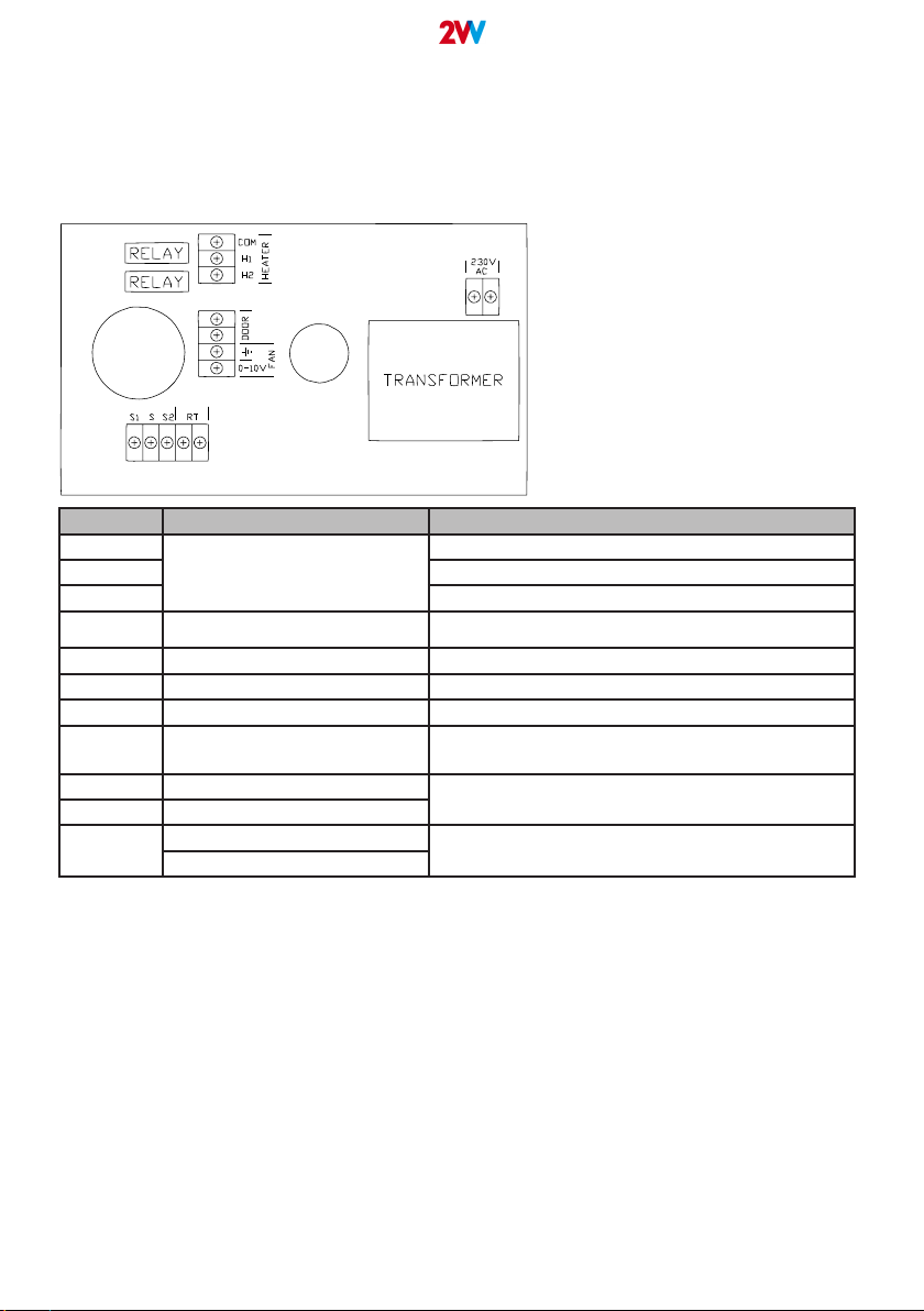
INPUTS AND OUTPUTS
Inputs:
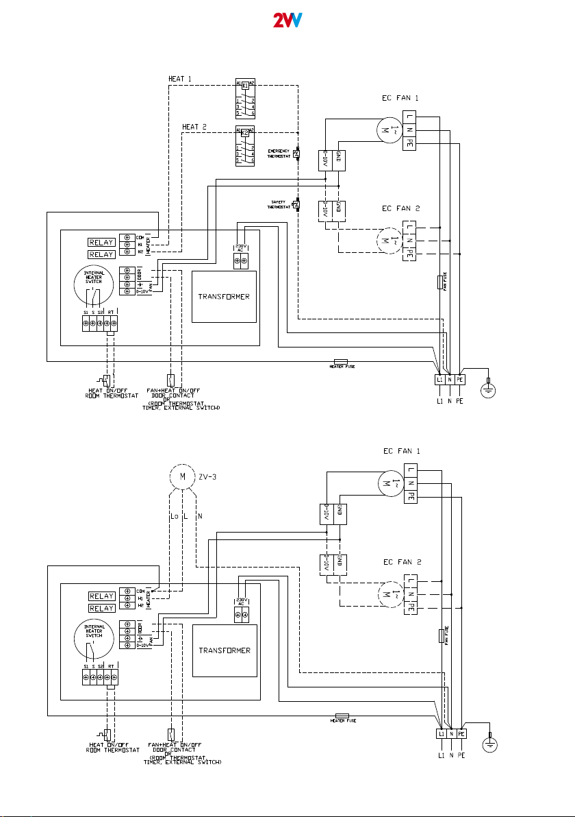
RT - Room thermostat
NOTE: Not used for ambient version of controller
• Input is set to connect an external, potential-free contact of room thermostat to switching on / off heating outputs H1 and H2
according state of room thermostat
• Controller responds to the connected/disconnected contact on the input (switching on / off heating), fan continues to run normally
• Default connection: connected contact (electrical bridge)
• Connected contact = Heating outputs H1 or H1and H2 is ON if heating is set to be used
• Disconnected contact = Heating outputs H1, H2 is OFF, even if heating is set to be used
DOOR – Door contact (room thermostat, external switch)
• Input is set to connect an external, potential-free door contact or room thermostat or external switch, to switch ON/OFF fan output
and heating outputs.
• Controller responds to the connected/disconnected contact on the DOOR input, switching on / off whole controlled product. After
OFF command is received the 5 seconds overrunning time is applied and then controlled product is set to OFF mode.
• Default connection: disconnected contact (without electrical bridge)
• Connected contact = product is switched to OFF (overrunning time is applied)
• Disconnected contact = controlled product runs on preset fan speed value and heating output
Outputs:
HEAT 1 – H1 (potential free output on board connected with terminal COM - Relay)
NOTE: Not used for ambient version of controller
• Controlled heating equipment of the controlled product is connected to terminal H1 - e.g.: 1st stage of heating by contactor
• Terminal COM is designated as input for control signal of the heating. Maximum load of relay contact is 230V/5A (Control signal
for heat can be used according installation needs e.g. 24VAC, 24VDC, 230VAC, depend on ON/OFF actuator selection)
• Connection output H1 is handled as 1st heating stage (contactor control signal or three-way valve opening phase)
• H1 output is switching power led to terminal COM
Functionality:
• HEAT 1 (H1) output is active only when control voltage to the ec fan speed output overcorss value 1,7V at last. (WARNING: Be
sure that controlled EC fan in the product is able to start before 1,7V control signal, to avoid start heating earlier then fan starts!!!)
• HEAT 1 (H1) output is active when starting 1st stage of heating as well as at start of 2nd heating stage HEAT 2 (H2) = HEAT
outputs are switched in cascade
• HEAT 1 (H1) output is inactive in case room thermostat contact connected to ROOM THERMOSTAT (RT) input is disconnected.
HEAT2 – H2 (potential free output on board connected with terminal COM - Relay)
NOTE: Not used for ambient version of controller
• Controlled heating equipment of the controlled product is connected to terminal H2 - e.g.: 2nd stage of heating by contactor
• Terminal COM is designated as input for control signal of the heating. Maximum load of relay contact is 230V/5A (Control signal
for heat can be used according installation needs e.g. 24VAC, 24VDC, 230VAC, depend on ON/OFF actuator selection)
• Connection output H2 is handled as 2nd heating stage (contactor control signal or three-way valve opening phase)
• H2 output is switching power led to terminal COM
Functionality:
• HEAT 2 (H2) output is active only when control voltage to the EC fan speed control output overcross 5V.
• HEAT 2 (H2) output is active when 2nd heating stage is selected and fan control signal value overcross the limit for 2nd heating
stage enable. Then HEAT 2 (H2) output is activated. HEAT outputs are switched in cascade, it means that H1 output is active
when H2 is active.
• HEAT 2 (H2) output is inactive in case room thermostat contact connected to ROOM THERMOSTAT (RT) input is disconnected.
0-10V/GND FAN speed output: Terminals: 0-10V, GND (Analog EC Fan Control Output)
• Output designed for stepless of EC fans control in range 0-10V signal. Maximum starting voltage signal for EC fan must be lower
or equal to 1,7V, because 1,7V is the value when Heat 1 output is activated.
• Heat 2 output is activated when fan speed control signal overcross 5V.
• The maximum number of EC fans connected to this output is 10.
WARINING: Be sure that controlled EC fan in the product is able to start before 1,7V control signal, to avoid start heating
earlier then fan starts!!!
WARINING: Length and execution of fan speed control signal cabling has inuence of voltage drop of the signal 0-10V!
Measure voltage of the control signal, on fan speed control input on the controlled fan to be sure that fan starts before
heating outputs are activated.

9
2 V V. Creating innovative solutions for you and your business since 1995.
WIRING EXAMPLES
BASIC EC (AGBA1-M-ECx-xx-E2) with two EC fans and electric heater with two steps of heating:
BASIC EC (AGBA1-M-ECx-xx-V1) with two EC fans and water heater:

10 2 V V. Creating innovative solutions for you and your business since 1995.
BASIC EC (AGBA1-M-ECx-xx-S0) with two EC fans:
BASIC EC (AGBA1-M-ECx-xx-V1) with two EC fans - Electric heater with one step:

11
2 V V. Creating innovative solutions for you and your business since 1995.
STORAGE AND DISPOSAL
STORAGE
Store the controller as follows:
1 Wrap the controller in suitable material, such as plastic lm, canvas etc. or place it in a suitable box.
2 Transport the controller into a dry space that is protected from weather conditions that could damage the packaging and negatively
affect the controller. The ambient temperature must be between +5 °C and +40 °C.
3 Do not place any heavy objects or material on top of the stored controller.
DISPOSAL ONCE THE CONTROLLER IS OUT OF OPERATION
When disposing of the controller, follow relevant regulations on waste disposal. It is best to dispose of components at a
specialised collection point to ensure recyclable materials are reused. Take any non-reusable parts of the air curtain to a
controlled waste dump.
RULES FOR SAFE OPERATION
▪Control and operate the controller only in accordance with this manual.
▪Always abide by the controllers operating temperatures.
▪Do not overstress the structure of the controller.
▪The controller should be protected by a suitable circuit breaker
Intheeventofre,thecontrollermustbeextinguishedwithaCO
2
orpowderreextinguisher.Neverextinguishitwithwater!
2VV, s.r.o.
Fáblovka 568,
533 52 Pardubice,
Czech Republic
T: +420 466 741 811
E: 2vv@2vv.cz
W: www.2vv.cz
Other manuals for AirGENIO
2
Table of contents
Other 2VV Controllers manuals
Popular Controllers manuals by other brands

Uponor
Uponor C-23 quick guide

Federal Signal Corporation
Federal Signal Corporation SIGNALMASTER 331102 instruction sheet

Phocos
Phocos ECO-T-MPPT 85/16 user manual

Link Communications
Link Communications RLC-3 user manual

Mitsubishi Electric
Mitsubishi Electric AJ65BT64DAV/DAI user manual

Ingersoll-Rand
Ingersoll-Rand X8I Detailed Description