Kailiu Instrument MGG/KL-DCB User manual

MGG/KL-DCB
Portable Electromagnetic Velocity Meter
Operation Manual

PREFACE
MGG/KL-DCB electromagnetic velocity flow meter adopts special designed exciting
system sensor and high performance signal processing system. 16-bit low consumption
embedded microprocessor and all digital signal processing ensure stable working, high
accuracy, and strong anti-interference. It can be automatic two-way flow velocity
measurement, multiple parameters display, self-diagnosis alarming, RS485(optional) and
storage function.
MGG/KL-DCB is the series model of our portable electromagnetic velocity/flow meter.
This series includes I-Model velocity meter; II-Model mathematical model integrated with
instantaneous flow and accumulative flow; III-Model high configuration sensor integrated
smart depth, velocity and flow meter.
This manual includes three kinds of instrument menu. The specific menu will be subject to
physical and slightly changes without prior notice.

Contents
ⅠSummary............................................................................................1
ⅡMain feature.......................................................................................1
ⅢMain technical parameters..............................................................1
ⅣWorking principle.............................................................................. 2
ⅤStructure.............................................................................................2
ⅥAssemble and introduction..............................................................2
6.1 Flow display terminals............................................................2
6.2 Velocity sensor:.................................................................... 3
ⅦMenu,keyboard and parameter setting......................................... 5
7.1 Velocity meter model menu...................................................6
7.2 Engineering mode menu........................................................7
ⅧInstrument usage..............................................................................8
8.1 Velocity measuring................................................................. 8
8.2 Flow measuring....................................................................... 9
8.3 Measurement requirements................................................ 10
8.4 Operating mode.................................................................... 11
8.5 Zero calibration(automatic zero setting)...................... 11
8.6 Historical data record and query........................................ 11
ⅨMaintenance (Notice)............................................................... 12
ⅩFault handling................................................................................. 12
ⅪProduct complete set..................................................................... 13
ⅫRandom documents.......................................................................13
ⅩⅢ Technical Support...................................................................... 13

1
MGG/KL-DCB Portable Electromagnetic Velocity Meter
I. Summary
The MGG/KL-DCB series of electromagnetic velocity meter is portable instrument flow
designed for the flow velocity/rate measurement. It’s professional for agricultural irrigation,
hydrologic monitoring, rivers flow monitoring, municipal water.
The low-power design and full digital signal
processing technology make measurement more stable and reliable. The range is wide
and high accuracy. It widely applies to the measurement of flow velocity and rate for
industry requires moving frequently such as agricultural irrigation, hydrology and water
conservancy.
II. Main feature:
No movable parts, no winding. No choked flow, no maintenance, avoid troubles of
other calibration and testing;
Micro-power design can last 80 hours when replace the battery(Ⅱ-model,optional for
level sensor);
LCD big screen back light display shows measuring data clearly in sunlight and night;
The instrument interface display velocity、flow(Ⅱ-model), accumulative
total(Ⅱ-model), level(Ⅱ-model), flow direction, electric quantity, alarm information,
running time, running status;
Simple operation, wading rod measurement, wire measurement and sailing
measurement are available choice.
Auto power shut off.
III. Main technical parameters
Range: Velocity 0.005m/s~10m/s(resolution 5mm/s);
Accuracy: ±1.0%FR+0.005m/s;
Acquisition time: Auto 10S~900S adjustable, hand control time;
Power: 1.5V*5pcs NO.5 battery;

2
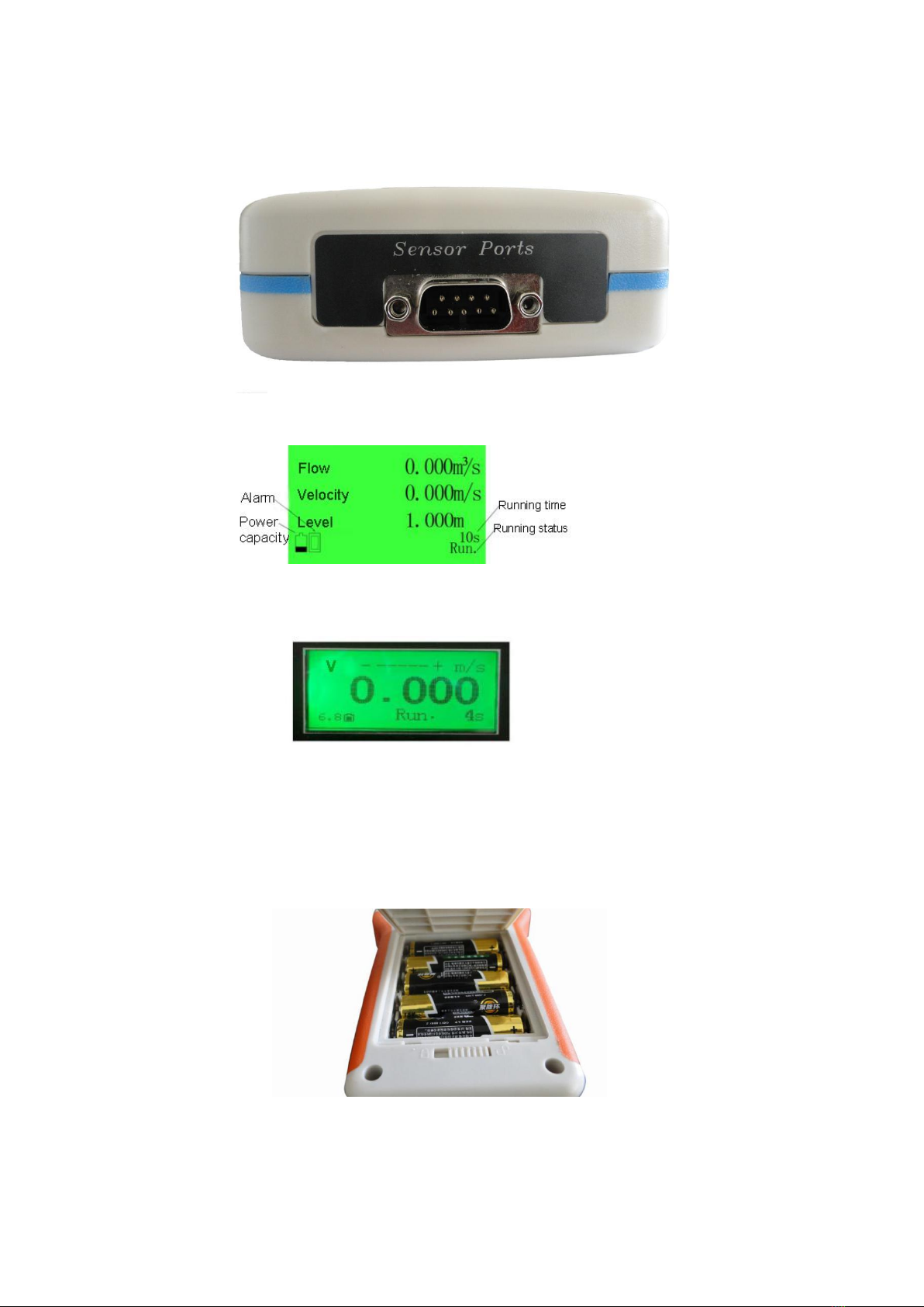
Display: LCD big screen back light display, flow(Ⅱ-model), accumulative
total(Ⅱ-model), level(Ⅱ-model), flow direction, electric quantity, alarm information,
running time, running status;
Physical interface: RS485(optional);
Conductivity: >20µs/cm;
Medium temperature: 0℃~60℃;
Ambient temperature: -10℃~50℃;
Display digits: 3 digits(X.XXX);
Size:204*100*35mm(Display);
Size:Φ32×460(mm)(Sensor);
Measuring rod:Normal 500mm×Sections (500mm×optional sections) or lifting
accessories.
IV. Working principle
The MGG/KL-DCB portable electromagnetic velocity/flow meter depends on the
Faraday's law of electromagnetic induction. The conductive liquid cut the magnetic line
and cause induced electromotive force when do the direction perpendicular to the
magnetic field lines in the alternating magnetic field along the measuring pipe. So we
install a pair of electrodes on the pipe wall which orthogonal with sounding pipe axis and
magnetic line. The electrodes can detect the induced electromotive force. It should be
directly proportional with the flow. Then the liquid’s flow will be exported by the detection.
The induced electromotive force signal will be converted to standard DC current
signal(0~10)mA, (4~20)mA or (0~5)kHz frequency output which was directly proportional
with flow signal by amplification of converter. So the measurement comes out.
The velocity equation
VKBDE
(K is induced electric potential magnification);
E--- Induced potential (V);
V
--- Mean velocity when the fluid cross the electrode surface in range;
B--- Magnetic induction intensity;
D--- Induction electric potential spacing.
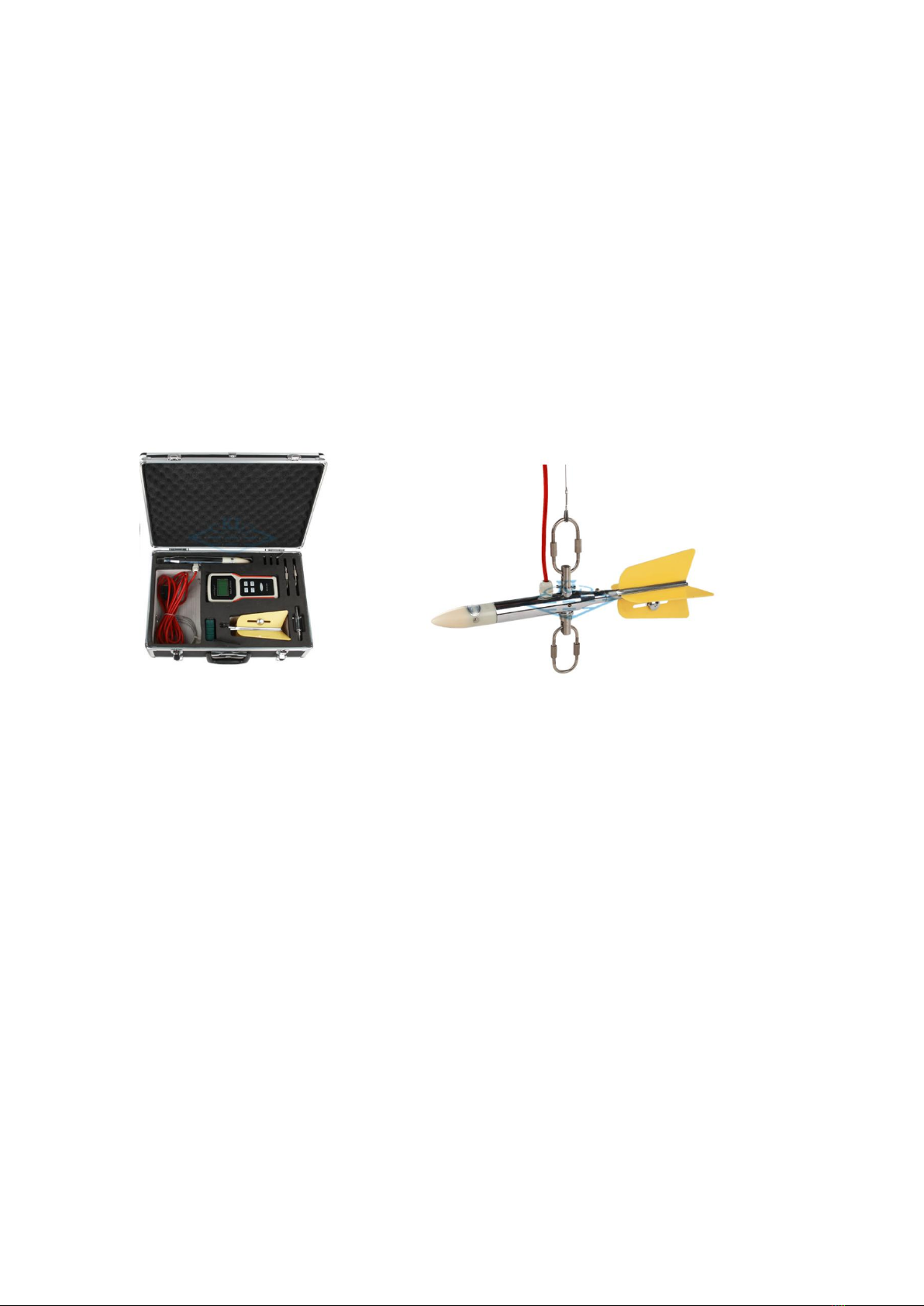
V. Structure
The instrument structure divides into three parts: electromagnetic velocity sensor
(III-model includes level sensor), flow display and wading rod(or suspension wire).
VI. Assemble and introduction
6.1 Flow display terminals

3
6.1.1 Display port
It uses for connecting the electromagnetic sensor. The outgoing line of electromagnetic
velocity sensor has completed coupler plug. Please directly insert the plug and tighten the
screws.
6.1.2 Display interface
Ⅱ-Model、Ⅲ-Model display interface:
Ⅰ-Model display interface:
6.1.3 Battery and communication port
The battery is 5*1.5V alkaline battery(convenient buy from market). The bottom is
communication port.
6.1.4 Switch Port
It uses for turning on and off.

4
6.2 Velocity sensor
The velocity sensor consists of velocity sensor and tail cable.
Velocity Sensor
The Tail

5
Suspension Loop and Axial Parts
VII. Menu, keyboard and parameter setting
Key description(One key is multi-purpose)
1. EXIT: Long press 6 seconds exit setting and return work interface in parameter setting
status.
2. +: Pageup or +1 key. Ⅱ-Model long press in main interface will enter basic parameter
modification interface.
3. -: Pagedown or -1 key.
4. SET: Save: press it to remove the cursor after parameter setting. The the parameter
will be completed and saved. Setting/Shifting: press it enter parameter
setting/modification in parameter setting status, then use for shifting. Long press 6
seconds enter password interface.
Password input(Under Engineering Mode)
The password must be inputted when modify status and parameter. Password can be set
arbitrarily in 5 digit number between 00000~99999, the default is 00000. In the working
status, long press “set” key more than 6 seconds, the converter password state “password
000000” will come out, press again “set” key and the first password digit display by white
line. Then use “+/-” to modify. Press “set” again to remove the white line below next digit.
Repeat 5 times and press “set” after complete to return parameter setting status.
Parameter setting and modification
When the instrument enter setting status, find the parameter you want to modify on the
display. Press “set” enter the position. Use “+/-” to add or minus and page turning on
different parameter. Use “EXIT” to ignore the parameter not be modified.

6
Modifing measuring time for example:
Enter Setting/Modification, use “+/-” to page up and down, find the measuring time. Press
“set” and there is white line under the time. Then use “+/-” to modify the parameter. After
completion press “set” again to remove the cursor and the parameter setting will be saved
at the same time. After all parameters settings completion, long press “EXIT” 6 seconds,
the program returns to the normal measuring status(The program will automatically return
to normal measuring status if there is not any operation).
7.1 Velocity meter model menu
PAGE
Ⅱ,Ⅲ-Model
menu
SET/UNIT
Ⅰ-Model
Menu
SET/UNIT
User
interfa
ce
Calibration
0=clear ,
1=Calibration
Calibration
0=clear ,
1=Calibration
Level
0~20.000m
Measuring height
0~20.000m
Bottom width
0~20.000m
Side wall
0~10.000
Edge distance
0~10.000m
Damping
0~60
Flow unit
0=m³/s;1=m³/h
Velocity digit
(0 ~3)= (0~
0.000)
Time
1(10s)
Time
1(10s)
Interval
1(10s)
Interval
1(10s)
Value number
0~999
Reverse
adjustment
0=off,1=on
Record
0~999
Auto shutdown
0=off,1=on
Auto shutdown
0=on,1=off
Backlight
0=off,1=on
Backlight
0=off,1=on
Note: “on” means the function turn on. “off” means the function turn off.
7.1.2. Usage menu and parameter details
Calibration: This parameter is zero calibration function. If there is zero deviation, please
use this parameter. This menu will be automatically calibrate on 01H 60S;
Level:Ⅱ-Model is manual input liquid level depth value. Ⅲ-Model is liquid depth
correction;
Measuring height: The height from velocity sensor to channel bottom(Necessary setting);
Bottom width: The width of channel bottom(Necessary setting);
Side wall: The factor of side wall which means aspect ratio of trapezoid side
wall(Necessary α=B/H);
Edge distance: The distance parameter from velocity sensor to channel side.(Necessary
setting);
Damping: Long measurement filtering time can improve the stability of flow display and

7
signal output. Short measurement filtering time shows fast corresponding speed.
Flow unit: Instantaneous flow divides m³/s and m³/h;
Velocity digit: The display of converter is 3-digit for choice according to the need;
Time: The velocity meter will sent average data within a certain period to display.This is
measurement period. Setting 0 means manual set measurement control time(Long
measurement period can improve stability of velocity display and signal output. It uses for
pulsating flow measurement field. Short measurement period means fast corresponding
speed uses for instant velocity measurement);
Interval: Interval between twice measuring 0~900s;
Value number: This parameter is for serial number which can be inputted by user. It uses
for recognizing value property. The value number auto add 1 every time;
Record: This parameter uses for historical data inquiry of value through page turning to
judge value property;
Auto shutdown: 1 is Time-limited model(1800s auto shutdown), 60s auto shutdown
without any operation. 0 is continuous working model;
Backlight: 0 is auto backlight shutdown when faulty operation. 1 is keep running.
7.2 Engineering mode menu
7.2.1 Engineering interface and parameters introduction
PAGE
Ⅱ/Ⅲ-Model
Setting/Unit
Ⅰ-Model menu
Setting/Unit
Engineeri
ng
interface
Conversion
factor
Factory
calibration
Conversion factor
Real value
Instrument
factor
Factory
calibration
Zero calibration
Manually set the
zero point
Model
Factory
setting
Velocity cutoff
Small velocity
cutoff
Level range
Factory
setting
Velocity digit
0~3
Max voltage
0~6.000
v
Transmission
address
1~255
Min voltage
0~1.600
v
Transmission
speed
1200~9600
Linear allow
0 or 1
Filter factor
10~200s
Velocity Value
1~5
Linear correction
0=off;1=on
Velocity
Calibration
1~5
Velocity Value
Factory setting
Sensor factor
0~6.0000
Sensor factor
Real value
Flow factor
0~6.0000
Language
0=Chinese;
1=English
Password
0000~9999
Password
0000

8
Conversion factor: This parameter is special factor of display manufacturer for unify the
circuitry of display measurement. Ensure every display consistency(irrevocable
parameter);
Instrument factor: It it reserve factor, it shows product relationship with velocity;
Model: Irrevocable parameter only for factory;
Level range: Ⅲ-Model have water level measurement function. Level meter range;
Max voltage: Ⅲ-Model output correction of max voltage;
Min voltage: Ⅲ-Model output correction of min voltage;
Linear allow: Control linear allow function. 0 is off, 1 is on;
Velocity value 1: The first point velocity measured value of linear correction;
Velocity calibration 1: The first point velocity corrected value of linear correction;
Velocity value 8: The first point velocity measured value of linear correction;
Velocity calibration 8: The first point velocity corrected value of linear correction;
Sensor factor: This parameter is velocity sensor calibration coefficient. Each sensor has
unique calibration coefficient which comes from actual calibration and marked on the
product certificate.It has been imbedding before delivery(irrevocable parameter);
Language: 0 is Chinese; 1 is English(Ⅱ-Model);
Password: It is adjustable parameter, the factory default is 0000;
Velocity cutoff: Low velocity cutoff display, unit is m/s(Ⅰ-Model);
Transmission address:The range of mailing address is 1~255, default is 1(Ⅰ-Model);
Transmission speed: 1200 ~9600bps is optional. The default is 9600. This menu
corresponds equipment with RS485 instrument(Ⅰ-Model).
Note:The address model of Ⅱ/Ⅲ-Model instrument is 1, baud rate default is 9600 and can
not be set.
Nonlinear velocity correction function instruction:
Nonlinear velocity correction function adopts below low velocity(0.5m/s) linear correction
in principle. It has eight section correction including eight velocity point and eight
correction coefficient.
Nonlinear correction coefficient means to be revised base on the original sensor
calibration coefficient. So please turn off nonlinear correction function and mark the
sensor factor, then turn on the function. According to nonlinear section of sensor,
measuring the velocity and correcting the setting. If the setting is suitable, no need to
calibrate.
Suppose: The original velocity is rate which has been calculated according to sensor
factor. The correcting velocity is rate which has been nonlinear corrected. Then the
velocity after correction has correspondence as following;
Notice: When setting velocity, please keep the relation as following:
Velocity 1>Velocity 2>Velocity 3>Velocity 4>Velocity 5.....>velocity 8

9
VIII. Instrument usage
8.1 Velocity measuring
This instrument is advanced measuring instruments uses for conductive liquid, simple
operation and convenient maintenance. Please connect the sensor and display exactly
and turn on the power on the display. Then put the velocity sensor into the measuring
channel point.
8.2 Flow measuring
The flow measuring needs to input channel measuring parameters: velocity measuring
margin, velocity measuring height, side slope ratio, channel bottom width, water
depth(water level adjustment, Ⅲ-Model water level can be automatically collected by
depth sensor).
Note: The measuring method includes one-point method and multi-point method. The
one-point method choose 0.6 times water depth and 0.5 times channel width. The
multi-point method choose as following:
8.2.1 Velocity distribution line within velocity of vertical distribution and vertical direction of
the water depth(Table 1):
Table 1
Water width(m)
Vertical number
>0 and <0.5
3-4
>0.5 and <1
4-5
>1 and <3
5-8
>3 and <5
8-10
>5 and <10
10-20
>10
>20

10
8.2.2 Recommended value of depth direction measuring point within flow range(Table 2):
Table 2
Depth
(m)
Point
number
<1
3-4
1-3
4-6
4-7
5-8
>7
6-10
8.2.3 Multi-point average velocity method classical formula:
Mode
Measuring Point Position
Average Velocity
1-poin
t
0.6*h
Vm=V0.6
2-poin
t
0.2/0.8h
Vm=(V0.2+ V0.8)/2
3-poin
t
0.2/0.6/0.8h
Vm=0.25(V0.2+2 V0.6+ V0.8)
4-poin
t
0.2/0.4/0.7/0.9h
Vm=0.25(V0.2+ V0.4+ V0.7+ V0.9)
5-poin
t
Close to surface/0.2/0.6/0.8h/Riverbed
Vm=0.1(V0+3V0.2+ 3V0.4+ 2V0.8+ VS)
6-poin
t
Close to
surface/0.2/0.4/0.7/0.9h/Riverbed
Vm=0.1(V0+2V0.2+ 2V0.4+
2V0.7+2V0.9+ VS)
Note: The sensor must be flooded about 10cm when close to surface. Please according to
the actual need to choose.
8.2.4 Flow calculation
8.2.4.1 Flow calculation between measuring point line
8.2.4.2 Line flow calculation

11
8.2.4.3 Side wall flow calculation
Note: KRis side wall factor, Please refer to the table 4:
Table 4
Side wall type
KR
Smooth without vegetation(concrete, steel or cement surface)
0.8-0.9
Brick without vegetation
0.7
Rough surface without plenty of vegetation
0.5-0.6
8.3 Measurement requirements
①Please try best to select point on flat area of channel or river. Avoid gate, curve,
inlet/outlet and ramp. The straight channel section should be long enough(upstream is
10-15 times channel width, downstream is 2-5 times channel width). So the flow
distribution will be more stable and uniform. And the data will be more accuracy.
②Velocity sensor position: Please point the measuring head to the upstream and ensure
the velocity sensor parallels to the flow direction. Waiting a moment for stable running of
sensor then resend the data. Avoid the primary interference signal input and eliminate the
electrode oxide film interference.
8.4 Operating mode
There are two operating modes: “Time” select 0 is manual continuity operating mode.
When select “Time” and period measuring fit “Interval”, it will be period-interruption mode.
Continuous mode is manual interval period measuring design. When the flow display is
working, the operating time will stop anytime. Then manually enter the next period
measurement. The display backlight will automatically turn off after 60 seconds without
any operation. If you want to turn on the display backlight, please press any button on
keyboard; The flow display will turn off automatically after 30 minutes without any
operation under power-save mode. And it will last work till battery out without power-save
mode(auto turn off select 0).

12
8.5 Zero calibration(automatic zero setting)
Zero calibration: Long press (+) enter the parameter setting mode and find “Zero
calibration”, then press “Set” to automatic zero setting. Then there will be white line under
the “00”, press “+” and modify “00” to “01” and press “set” again. The automatic zero
setting will be turn on. The automatic zero setting will cost 60 seconds. The screen time
digital will display from 60 to 0. The automatic zero setting complete. Zero calibration is
necessary when needs and verify. Please make sure the medium statically and surround
the electrode. The vessel must be non-conductive material(Picture as following for
example)
Note: Operating instruction:
1. The electrode should be in the center of medium. Metal portion touch the medium.
2. Please keep static during zero calibration both medium and sensor.
8.6 Historical data record and query
Ⅱ/Ⅲ-Model display can record 1000 items historical data.
8.6.1 Data record and storage
The instrument will record internal storage number automatically. You can set original
value in “Setting”, each measuring will add 1 automatically and cover the current value
after 1000 items.
8.6.2 Date query
Please turn on the display and keep normal measuring status, press “+” or “-” to page up
and down, find the date query and press “set” select record number, then press “Exit”. The
program will enter data query display. You can use “+” or “-” to inquire all the historical
data. Each date has number, so you can check the date according to order number. If you
want to find some items. Please enter the number in data setting menu then exit the
parameter setting status. It will display this item. When you complete, please press “EXIT”
to quit data query display and get back to normal measuring working status.
8.6.3 Date query interface instroduction

13
IX. Maintenance (Notice)
9.1 Please wipe the electrodes with clean wet cloth before use after long time place. Then
immerse into the water 3-5 hours;
9.2 Please keep the sensor clean, avoid mud and grease;
9.3 Please keep the electromagnetic velocity display clean and dry;
9.4 Please remember to change the battery.(Battery is 1.5V*5, long time place should
remove the internal battery).
X. Fault handling
NO.
Alarming
Information
Treatment
1
Low press
alarm
Please replace battery
2
Exciting alarm
1. Excitation line loose;
2. Excitation line fault;
3. Return to factory.
3
Bare electrode
1. Velocity measuring height
setting is not current;
2. Water level sensor damage;
3. Return to factory.
XI. Product complete set
10.1 MGG/KL-DCB Portable velocity display 1set
10.2 Velocity sensor 1set
10.3 Velocity meter tail 1set
10.4 Steel measure tape 1pcs
10.5 Allen wrench 3pcs
10.6 Measuring insert rod(Order length) 1set
10.7 Measuring steel wire(Order length) 1pcs
XII. Random documents
11.1 Operation instruction 1pcs
11.2 Product certificate 1pcs
11.3 Package 1pcs
11.4 Feedback 1pcs

14
XIII. Technical Support
Customer Feedback
Dear Customer:
Thank you for your business. Please complete the form below to improve our quality and
service. Your cooperation will be highly appreciate.
Product
Model
No.
Inspector
Certification
Problem and suggestion:
Name
Add.
Tel.
Date
Signature
Table of contents
Popular Measuring Instrument manuals by other brands

Bender
Bender VMD420 manual

Sencon
Sencon SI9500 instructions

Kitchen Brains
Kitchen Brains BB4 operating manual

Scion Instruments
Scion Instruments 456-GC Reference manual

Hart Scientific
Hart Scientific 9105 user guide

Stuart Turner
Stuart Turner MAINSBOOST MONOBLOC 22MM C Installation, operation & maintenance instructions