KAKA Industrial CS-12 User manual

COLD SAW
Model: CS-12/CS-14
Opertation Manual

1.Introduction
1.1 General
By means of this operator’s manual you can get acquainted with your circular sawing machine from the
range CS-315 and CS-350.
We advise you to read the enclosed operator’s manual carefully, so that you will soon be familiar with the
operation and maintenance of the machine. This will minimize the times of ‘downtime’.
We also ask you to pay special attention to the safety aspect that will be dealt with in chapter
1.2. Safety regulations
Should any unexpected malfunctions occur, which can not be remedied by means of the instructions
given in this operator’s manual, please apply to your nearest sales outlet.
Read this manual carefully, in order to get thoroughly acquainted with the operation of your machine.
Secure the machine to the floor. The floor on which is the machine is secured, must be flat and rigid.
Prevent unwanted starting of the machine. See to it that the speed selector switch is in the off
positions while the machine is being connected.
Provide a sufficient grounding of the machine.
Avoid dangerous working conditions. Do not use the machine in a damp or wet environment
Never work without a safety guard.
Wear eye protection device. Dot work with trailing pieces of clothing which could be caught by
moving parts. Preferably wear ear mufflers and mask during operation.
In case of danger resulting from defects, immediately contact the person in charge of the machine.
When handle heavy workpiece, it is advised to use proper hoist device.
When the workpiece is long, additional support device (e.g. table) must be used to support the
workpiece to prevent hazards arise from the falling of the workpiece.
Do not saw workpieces larger than those for which the machine was designed. before sawing clamp
the workpiece tightly.
Do not saw with excessive pressure on the saw blade. This can cause breakage of the saw blade.
Replace worn or damaged parts in time and do not work with blunt saw blades. Comply with the
lubricating instructions and keep the machine clean.
Use original spare parts and accessories only. For operator’s safety, special spanner for change
saw blade is provided.
The speed adjustment must be done only when the machine stops completely.
Disconnect the mains while carrying out repairs or replacing parts, Make sure the saw blade is not
resting on the material when the machine is switched on.
• HAVE YOUR MACHINE INSTALLED BY AN AUTHORIZED INSTALLER!!

1.3 Guarantee
Defects to goods delivered of which can be proved that they have occurred within 6 months of delivery
as a result of an incorrectness in the design or of faulty finish or use of bad materials will be repaired by
us free of charge.
Claims about externally noticeable faults are to be put in at the time of testing or inspection in our factory,
resp. at the latest, or in case no test or inspection takes place in our factory, within two weeks after
reception of the goods. If tills period is exceeded all claims relating to the faults concerned will expire.
Claims about faults which are not externally noticeable are to put in as soon as possible, however, not
later than two weeks after expiry of the period of guarantee. If this period is exceeded all claims relating
to the faults concerned will expire.
The purchaser's appeal for guarantee does not relinquish his contractual obligations towards us. As long
as the purchaser does not fulfil his contractual obligations towards us we deny our obligation to render
guarantee.
2 Technical data
2.1 Main group
CS-350 and CS-315 range comprises model as follow :
CS-315 and CS-350 LOW SPEED SAWING SPEED POS.1:18.5M/MIN IN POS.2: 37M/MIN.
CS-315 and CS-350 HIGH SPEED SAWING SPEED POS.1:37M/MIN IN POS.2: 74M/MIN.
2.2 Survey and sketch of dimensions
(see fig. 2,01)
Dimensions and weight of the machine
CS-12
Height(H): 175mm
Width(B): 555 mm
Depth: 970 mm
Weight: 185kg
CS-14
Height(H): 1800mm
Width(B): 555 mm
Depth: 970 mm
Weight: 190kg
NOTE: This manual is only for your reference. Owing to the continuous tmprovemeni.changes
may be made at any time with no obligation on the part of machine. And please note the local
voltage for operating this electric machine.
Fig.2
.01
C
H

2.3 Requirement of operating site
This machine is designed for operating on the site:
- Voltage The steady-state AC power supply is 0.9~1.1 times of the rated value.
- Frequency 0.99~1.01 times of rated frequency (continuous working)
0.98~1.02 times of rated frequency(short period working)
- Harmonics The sum of 2nd-5th distorted harmonic must not exceed 10% of RMS of voltage, maximum
2% of RMS of line voltage is allowed to add to the sum of 6th-30th harmonic.
- Unbalanced voltage of 3-phase power supply
Negative sequence component are not allowed to exceed 2% of the positive sequence component.
- Short-circuited protection and incoming line
The machine shall have short-circuited protective device at the power supply end by the end-user, the
rated current shall be 5A, and the diameter of the incoming line of the power supply must not be less
than 1.5mm2 (single phase) and 1.5mm2 (PE).
- Overvoltage protection
Overvoltage protection device shall be provided in the power supply line by the end user.
- The height above sea level of the machine installation doesn’t exceed 1000m;
- The ambient temperature range of air is 5℃~40℃.
- The relative humidity doesn’t exceed 50% at a maximum temperature of +40 ℃ .
Higher relative humidity may be permitted at lower temperature (e.g.90% at 20℃)
- Lighting of the work zone should be at least 500lux(provide by end user).
- The installation site of the machine shall be away from undesirable vibration, shock or bump.
3 Description of machine
3.1 Description
Circular Saw consists of 6 models which have the same construction and each of which meets the same
high quality requirements.
The constructive differences apply to the application and the specific wishes of the user.
All versions are standardly equipped with a machine based with incorporated cutting oil tank and pump.
All versions are fitted with a tolerance-free long-life worm and worm wheel. The worm gear runs in an oil
bath case and is virtually maintenance-free.
All versions are fitted with a double, self-centring material vice.
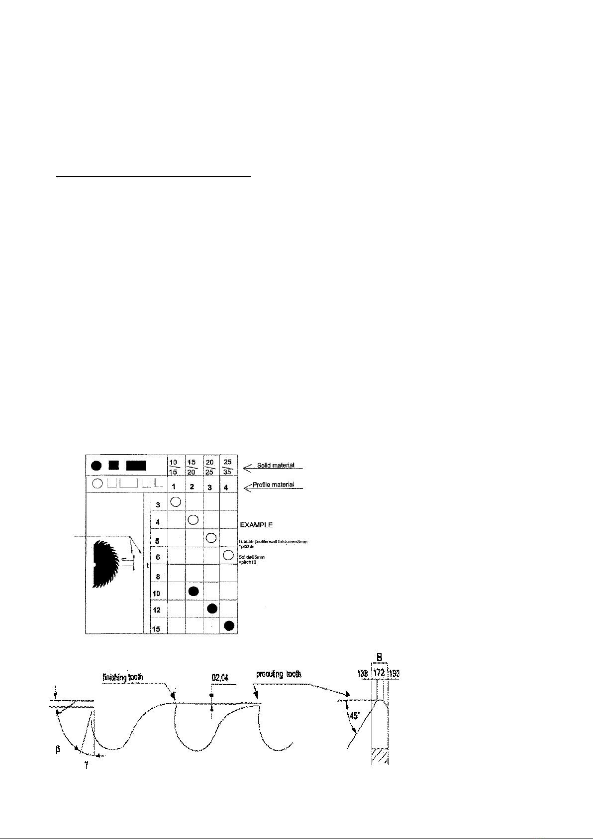
The machine can mitre, slot and cut recessed corners in both directions. For this !ast form of operation it
is of special importance that the saw unit as a whole can turn around its axis.
The machine can saw various profiles in various dimensions and cross-sections. A survey of these can
be found in chapter 5,3 "Sawing capacity",
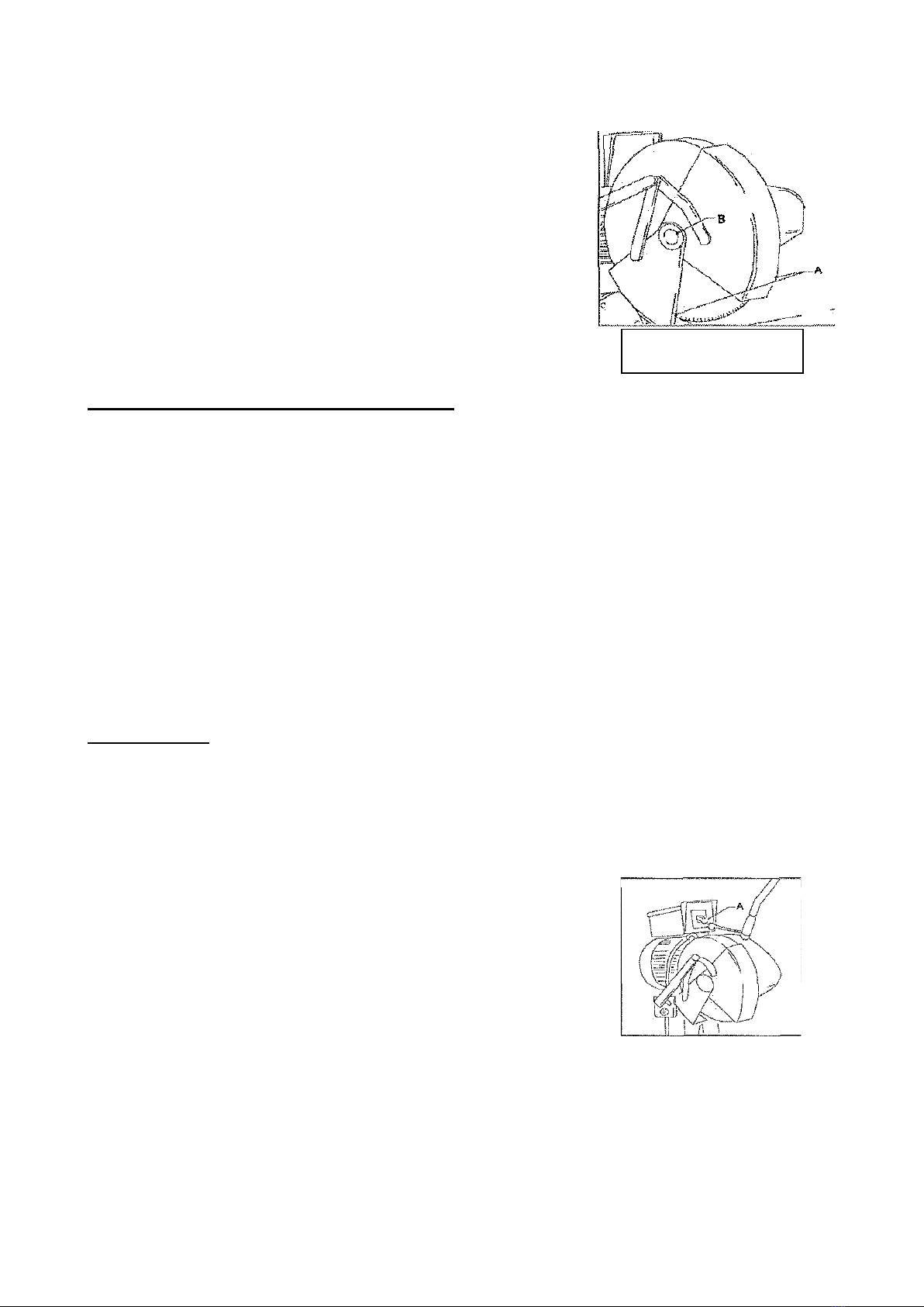
The patented protective guard opens and closes automatically. The saw blade can easily be exchanged.
The machine as standard is equipped with an adapter for the saw blade (see technical data). If ordered a

different adapter can be supplied.
3.2 Intended use
According to the choice of saw blade referred in No.5 chapter, it can cut many kind and shape steel. For
example CARTON STEEL, ALLOY STEEL, COPPER , ALUMINIUM and so on. But it can not cut
flammability and explode material, like natrium and magnesium .
3.3 TRANSPORTATION OF MACHINE
1.The store and transport of machine’s temperature must be from -25C to 55C.
2. The bolt (A in fig3.03) of basic must be fitted before transport and store.
3. When you transfer the bolt of the swinging ring ,you should loose B-bolt of oil-mouse
4. You should swing the machine with nylon rope.Then put the machine to the bottom pallet, fitted with
bolt.
5. Covered the packing case. And put the basic to another case.
6,As this machine’s weight is 110kg , it is recommended that the machine should be Transported
with help of lifting device.
In fig 3.04
Warning:
- Tighten all locks before operating.
- ALWAYS keep proper footing & balance while moving this machine, and only use heavy-duty fibre belt
to lift up the machine.
4 Installation
Avoid installing the machine in damp, dirty or poorly lit environments.
Make sure that the machine has all necessary protection.
Electric installations should be performed by the authorized electrician.
Be sure that the machine is set up securely or anchored in place.
Attention: There is risk of overturn when machining heavy workpiece. We recommend to fix the machine
to floor before operating as following:
Place the machine on a stable foundation. The bolt are fixed to the floor at the position indicated in the
figure below.(in fig.2.01c)
FIG3.03
A
B
FIG3.04

4.1 Installation mounting
Unpack the machine.
• Determine where the sawing machine will be placed, in doing so take into account the feed and
discharge of materials, optional built-on accessories, maintenance and repairs.
• Remove the plastic plug from the saw head (fig. 4.01 B). If so required a lifting hook M20 DIN 580 can
be screwed into the hole.
• Race the saw unit - if necessary by means of hoisting equipment - on the machine base (cover at the
rear) and attach each other.
•Secure the machine on the floor. The necessary holes have already been made in the machine base.
• Install the handle in the saw head and lock it(fig 4.01 A).
• Install the 3 short handles in the boss of the machine vice,
• Install the stretcher in the clamp.
• Slide the plastic tube coming from the cooling pump onto the tap which is positioned on top of the
protective guard of the saw unit (fig 4.02A).
• Check on the level gauge of the saw head whether it contains sufficient oil. if necessary fill up (fig. 4.01,
see arrow).
• Install the cover at the rear of the machine base.
• Install the saw blade (see chapter 5.4)
4,2 Non-recurrent adjustment
This adjustment is concerning the LOWEST POSITION of the saw head. Follow the instruction on the
saw flange (fig. 4.03, see arrow). This instruction is also important when changing the saw blade.
4.3 Coolant
The use of proper cutting fluid is essential to obtain maximum efficiency from a band saw blade. The
main cause of tooth failure is excessive heat build-up. This is the reason that cutting fluid is necessary
for long blade life and high cutting rates. Cutting area and blade wheels should be kept clean at all time.
The rate of coolant flow is controlled by the stop valve lever (J) in Fig.4.02.which directs the coolant onto
the blade . The lever (J) is shown in the off position.Circulation system
Fill the tank with coolant. Use sawing coolant and absolutely NO cutting oil. recommends oils, available
Fig 4.02 Fig 4.03
When you put on
new blade reset
adjusting screw.
J

from your dealer. The coolant must be diluted in wear in a ratio between 1:10 and 1:20, depending on the
kind of material. Add the oil slowly to the water while stirring it continually. The filler cap is positioned at
the rear of the machine base. The capacity of the tank is 10 litres.
The coolant circulates and for the larger part flows back into the tank. After some time
The coolant wiil be used up completely and the tank will have to be filled again. A filter is also
incorporated in the coolant circuit.
For general metal material (e.g. steel, copper), it is recommended to use BP-70 coolant.
Warning: Some material has fire hazards, e.g. Magnesium. Care must be taken when cutting such
material. Special coolant must be used for these material. Please get detailed information from
professional coolant supplier for special coolant.
-When adding coolant, attention should be taken that the coolant level should not access the line marked
on the coolant container.
4.4 Electricity
Have the electrical connections made by a qualified installer. Connect the machine in accordance with
the electrical diagram applying to your machine.
Electrical installations should be always performed by authorized electricians.
1)Make sure that the correct voltage is supplied to the machine.
2)Set up the electrical connections according to the attached circuitry. Connect the electricity on the
main line’s automatic circuit breaker.
3)Make sure that the circular saw has the correct rotation direction.
Warning: Note the earth screw!
Saw motor
Two-speed pole changing motors are suitable for one mains voltage only. Therefore check whether the
voltage indicated on the motor plate complies with the local mains voltage.
• Check whether the direction of rotation of the saw pitch corresponds to the arrow on the safety guard.
•If the motor rotates in the wrong direction two phases wires must be switched.
Overvoltage protection device shall be provided in the power supply line by the end user.
5 Operation
When operating at the first time, please check the back extension spring whether it is fastness, whether
it is fastness between handle switch and handle .You must move the head of machine and protection of
cutter up and down . Make sure they can convenient to open and close. Then you can operate it as
follow :
5.1 Selection of the sawblade
After years of research we recommend you to use only Time winner saw blades. These HSS saw blades
are of top quality and are made of the base material DMO 5, These saw blades have undergone a

Fig.5.01
Fig.5.0
1
special heat treatment which guarantees high wear resistance. Owing to the micros porous structure the
cutting oil is transferred quicker into the saw cut. This means longer life before resharpening and less
chance of cold welding. The quality of the saw blade is of great importance. The selection of the correct
pitch depends on the material to be sawn. The selection of the correct pitch and rake angle is of great
importance for the life of the sawblade.
5.2 Selection of pitch and tooth form
If the pitch is too small and the length of the cut too large, the cut material cannot be taken into the tooth
cavity. The chip wi!l get stuck in the tooth cavity, so that it is inactive in case of a second cut of the same
tooth. This can cause the saw blade to jam and break.A pitch which is too large will cause the sawing
tooth to hack as a result of which teeth can break free. For the sawing of profiles it must be taken as a
rule that at least two teeth of the saw blade are in cut.
Fig, 5.01 will help you determine the pitch for the material to be sawn.
Hint
If a short, hard jerk is felt during sawing and the saw starts jolting, do not continue. In such cases it is
almost certain that at one or more places a fine chip has fused away at the flank of the saw tooth.
This causes the saw to be slightly thicker at certain places. Remove the saw blade and remove the fused
material with a fine-grained, high-grade saw file.
Selection of the tooth form
Besides a well selected pitch the following factors, too, are of great importance to facilitate the correct
machining of the material (fig. 5.02)

Clearance angle (5 and rake angle 7 of the tooth have been selected correctly in view of the material to
be sawn, the principle is as foifows.
Ma
terial
Clearance angle
Rake angle
steel
8
22"
stainless steel
6
15'
Non-ferrous 12 25"
Form of tooth cavity large enough compared to the pitch.
A quick removal of the cut material and a correct depth and rounding of the tooth cavity are of the utmost
importance. The tooth cavity must be large enough for the removed chips to be bend as long as the tooth
is cutting. When the cutting tooth leaves the saw cut, the chip drops out of the tooth cavity.
The alternate saw (alternately bevelled edge) is often used for smalt pitches, especially up to 4mm.
The precutting and finishing teeth are used for larger, solid material, usually from pitch 4 mm onwards.
These teeth ensure that the chips are not all of the same length. If a chip were to be cut out tie normal
way, it would get hot, expand and become wider than the width of the cut. This wouid cause it to get
stuck, as a result of which the chip could not be removed from the cut. The finishing tooth must be
positioned 0.2 to 0.4 mm higher than the precutting tooth.
The larger the pitch, the higher the precutting tooth must be placed as compared to the finishing tooth.
Consequently, only special machines are suitable for regrinding these teeth. When the blade has lost its
cutting power, do not strain it. As a result the teeth may break off, which doubles the regrinding costs.
5.3 Sawing Capacity
For the maximum capacity in mm see the schedule for the profile figure/cross-cut in relationship with the
mitre angle. Whit 90° we mean straight sawing. Use the table from the machine type you have.
CS-315
90°
60°
45°
100
100
100
110x110
100x100
100x100
110x110
100x100
100x100
110x110
100x100
100x100
140x100
120x100
100x100
55
45
45
50x50
40x40
40x40
CS-350
90°
60°
45°
120
115
105
110x110
100x100
100x100
110x110
100x100
100x100
110x110
100x100
100x100
140x100
120x100
100x100
55
45
45
50x50
40x40
40x40

5.4 Installing and replacing the saw blade
• Set the main switch in the off position.
• Put the saw head in the upper position.
• Open the guards (fig- 5.03A).
• Release the socket head screw M8 of the saw spindle
(fig. 5.03B) and remove the saw flange.
• Remove the saw blade.
• Carefully clean the saw spindle and the saw flange.
• Installing is done in reverse order. Pay attention to the direction of rotation of the sawblade. Make sure
the saw blade is placed flush against the flange of the saw spindle. Check the setting of the sawing
depth {see chapter 4.2}. Do not forget to close the safety guard.
5.5 Saw feed
Manual saw feed
The saw feed is determined by hand. The saw is lowered onto the material by means of the handle. Press the saw
blade firmly onto the material, without using unnecessary force. When the saw pressure is too high this can cause
the saw to break; when the saw pressure is too fow, the saw will rapidly go blunt.
5.6 Sawing speed
The saw speed wilt be selected by the switch (fig, 5.04A)
The following cutting speeds are possible:
CS-315 and CS-350 LOW SPEED SAWING SPEED POS.1:18.5M/MIN IN POS.2: 37M/MIN.
CS-315 and CS-350 HIGH SPEED SAWING SPEED POS.1:37M/MIN IN POS.2: 74M/MIN.
Every material has it's own cutting speed. Below advice for some materials;
18, & 36r/min > For steel alloy e.g. stainless steel
Fig.5.03
Fig 5.04

5.7 Clamping the material
It is of the utmost importance that the material is safely clamped in the double material vice, so that it
cannot tilt over or even move during sawing. In order to work efficiently, the material must always be
clamped in such a way that the contact surface of the saw and the material is as small as possible. For
instance, saw fiat material on its thinnest side; this will considerable shorten sawing times.
When very short pieces have to be sawn, and consequently only half of the material vice will be used, in
order to prevent it from pulling out of alignment, a piece of material of equal thickness must be clamped
in the other half of the vice. In this way the material is clamped tightly and evenly. Application of special
vice jaws Is recommendable for repetitive work
The sawing depth can be limited by means of an adjustable ring, see chapter 4.2
Mitre-sawing
Pull the clamping rod (fig. 5.06B) to the right and turn the sawing unit in
the required mitre position. The position can be read out on the scale
division (fig 5.06A). Then fasten the clamping rod again. Do not use
unnecessary force, a slight pull will suffice. Before clamping the
material, check whether the saw is running completely clear between
the jaws of the material vice. Place the sieel vice jaws as closely as
possible to the saw.
5.8 Cooling
Cooling is of great importance to the life of the saw blade. After thorough investigation it has been
established that the emuisifiable coolant oils absolutely prevents - among other things - the forming of
so-called buiit-ups (the fusing of cut material to the tooth point flanks). This will prevent a jolting saw,
which results in damage and breakage. Oils forms a lubricating film on the saw tooth points, so that, in
case of increased saw feed, the high pressure between chip and tooth (chip surface of the saw tooth) will
not lead to overheating of the saw. Here it is important that a correctly directed stream at the cutting
edges of the saw ensures an ample supply of coolant for the removal of chips and the elimination of
frictionai heat.
5.9 Start/stop
• Make sure the material has been fed.
• Check the sight-glass to see whether there is sufficient oil in the saw head. If necessary top up with BP
GRXP 680 (ISO) through the vent hole in the handle.
• Check the depth setting of the saw blade.
• Check whether the vice jaws are suited for this material.

Fig.6.03
A
• Adjust the material vice to the material
• Switch on the machine with the main switch.
Select the required speed.
• Open the coolant cock on the safety guard (not in case of atomized lubrication).
• Start machine with the switch on the pulling rod
6 Maintenance
6.1 General
Clean the machine after it has been used and provide rust protection by applying a protective oil.
Regularly remove the chips which gather underneath the vice jaws. In doing so use a thin, flat brush and
NEVER an air jet.
The gears, the worm and the worm gear are subject to wear. The moment the replacement of these
parts is due, depends on the usage. You can order a complete set, including instructions for disassembly
and assembly from your dealer. This kit is available from stock.
Regularly clean the coolant tank. This will considerable lengthen the life of the pump.
Check the condition of the oil filter in the cooling circuit, If the filter is severely polluted, it needs to be
cleaned or replaced.
Check the oil level in the saw head every week.
Check the oil level of the saw feed tank and refill if necessary (see chapter 6.3).
Check the oil bowl and the water separator every day. Refill the oil bowl with BP HLP 15 or a type of the
same quality.
Remove the water from the water separator of the air unit. With the PK-versions the glass can be
screwed off.
6.2 Lubrication
The gear box with the gear parts must be rinsed clean at least once per six months, depending on the
use of the machine. Loosen the plug at the bottom of the saw head and drain the oil, Rinse the unit with
petroleum and drain it thoroughly. Fill the unit with BP GRXP 680 (ISO); the 350-series with 1.1 litre.
Check the oil level on the sight-glass. If the saw head gets too hot while used continuously, the oil level in
the saw head may be too high.
Once every three months the grease nipples of the pivots of
the saw head must be greased with a universal grease.
The 350 and SCO-version has one grease nipple (fig. 6.03).
The threaded spindle, the guide rods of the material vice
and the guides of the machine bed must be oiled regularly.

6.3 Grinding the sawblades
It is only possible to work efficiently with circular sawing machine when the saw blade is reground in time.
When the saw has lost its cutting ability, do not try to continue sawing by puting the handle harder, for
this can cause teeth to break and the cost of regrinding doubled,
Regrinding should only be done on special machines, constructed for this kind of work. Besides that it is
advisable to check the saw optically in your own factory after they have been reground. In these optical
checks special attention must be paid to the rake angle and the clearance angle.
7 Trouble shooting
Trouble
Possible cause
Remedy
Excessive
bouncing or
breaking of
the saw.
1. Speed an/or saw feed too high.
2. Teeth blunt, tooth cavities too small,
3. Wrong coolant
4. Saw jolts because chips remain in the saw
cavity (cold-welding on the saw).
5. Saw installed incorrectly with respect to the
direction of
rotation.
6. Worm and worm wheel
Use oils
Have the saw ground
and the tooth cavity
polished, so that the
chips can easily slide
through the tooth cavity.
Turn the saw and check
the teeth.
Replace.
Motor does
not turn
1. Motor incorrectly connected,
2. Relays or motor defective.
3. Selector switch is in the OFF position.
4. Thermal protection of motor defective.
5. Fuses blown
6. Emergency stop butt
Cooling
system does
not work
1. Cock on saw guard in closed position.
2. Pump incorrectly connected.
3. Pump defective
4. Cooling tank empty
5. Suction pipe of cooling pump obstructed.

PARTS LISTS
Part No. Description Qty. Part No. Description Qty.
101 Pedestal 1 109 Sticker electro 1
102 cover 1 110 Sticker general
1
103 support pump
1 111 Pump set
230/40QV50HZ
1
104 screw 6 x 12 4 112 Filter 1
105 Spring washer 6 6 113 Screw M6x12
106 Screw M10 x 100 2
107 Screw M6 x 12 2
108 Spring washer 8 2

Part No. Description Qty.
201 Angel Scale 1
202 Type Shield 2
203 Spring 2
204 Rivet 10 2
205 Screw M10x100 2
206 Nut M10X25 4
207 Filter 1
208 Spring fixed plate 1
209 Spring fixed plate 1
210 Washer 4
220 Base plate 1
221 Swivel block 1
222 Greasing nipple 2
223 Shaft 1


Part No. Description Qty. Part No. Description Qty.
302 Nut M10 4 337 Vice plate left 2
303 Ring 2 338 Vice plate right 2
304 Mat board 2 339 Vice jaw at the front 1
305 Bolt 4 340 Socket screw 4
306 Rubber cover 1 341 Handle rod+knob 3
307 Pipe hoop 1 342 Knob 3
308 Nut 1 343 Plastic cover knob 1
320 Pin 2 344 Boss 1
321 Knob 1 345 Guiding shaft 2
322 Mitre handle complete 1 346 Vice base 1
323 Stud 1 347 Socket screw 2
324 Nut 1 349 Vice jaw at the back 1
325 Tensioning nut 1 350 Support block
326 Nut 3 351 Socket Screw 2
327 Bolt 3 353 Threaded shaft 1
328 Pressure plate 1


Part No Description Qty. Part No. Description Qty.
401 Ring 1 428 Locking ring 1
402 Push down seat 1 429 Bearing 1
403 Bolt 1 430 Ring 1
404 Nut 1 431 Bearing 1
405 Oil mark 2 432 Worm shaft 1
406 Needle bearing 1 433 Gear housing 350 1
407 Circlip 1 434 Worm wheel 1
409 Stopper stifled 1 435 Bush 1
410 Bearing 1 436 Circlip 1
416 Sunken key 1 437 O-ring 1
418 Ring 1 438 Socket screw 3
419 Dowel pin 2 439 Bearing block 1
421 Drain catcher 1 440 Sunken key 1
422 Oil catcher 1 441 Saw shaft 1
423 Nut 1 443 Socket screw 1
424 Gear 1 450 Stopper stifled 1
425 Spacer ring 1 451 Ring 1
426 Socket screw 4 471 Packing 1
427 Stop ring 1 473 Screw 2

This manual suits for next models
1
Table of contents
Other KAKA Industrial Saw manuals