4
Section 1: Welcome to the OBD II System Tester
1-1 Overview
OBD II (On-Board Diagnostic, second generation) systems are designed to meet or
exceed a set of standards and regulations designed to im rove air quality. The
Environmental Protection Agency (EPA), in conjunction with California Air Research
Board (CARB), issued these standards and regulations through the Clean Air Act
of1990. OBD II systems are required to monitor the erformance of emission related
systems and their com onents. The ability to detect hard and intermittent faults are
further requirements of an OBD II com liant system. The Society of Automotive
Engineers (SAE) defined several standards for OBD II systems. These standards
include criteria for the diagnostic link connector, communication, Diagnostics trouble
codes (DTCs), descri tor names, and other re air information.
This OBD II System Tester will work on OBD II com liant cars and light trucks. If you
use a vehicle service manual along with the tester, you will be able to diagnose and
re air many automotive-related roblems. Before roceeding, make sure you have
read and fully understand the material in this Manual.
1-2 The OBD II System Tester
KAL Equi s OBD II System Tester was develo ed by ex erts in the automotive
service industry to hel diagnose todays vehicles and assist in troubleshooting
rocedures. When a roblem occurs in the vehicle, its com uter will store a record of
the event and take corrective action to adjust the circuit at fault. The OBD II System
Tester will allow you to monitor these vehicle events and read DTCs from the
com uters memory to in oint roblem areas. The OBD II System Tester will
inter ret the com uter signals and rovide you with a real time readout of vehicle
data. In addition, the Code Looku feature allows you to reference code descri tions
without having to age through an instruction manual. A detailed descri tion of the
functions are rovided in Section 2: Diagnosing with the Tester.
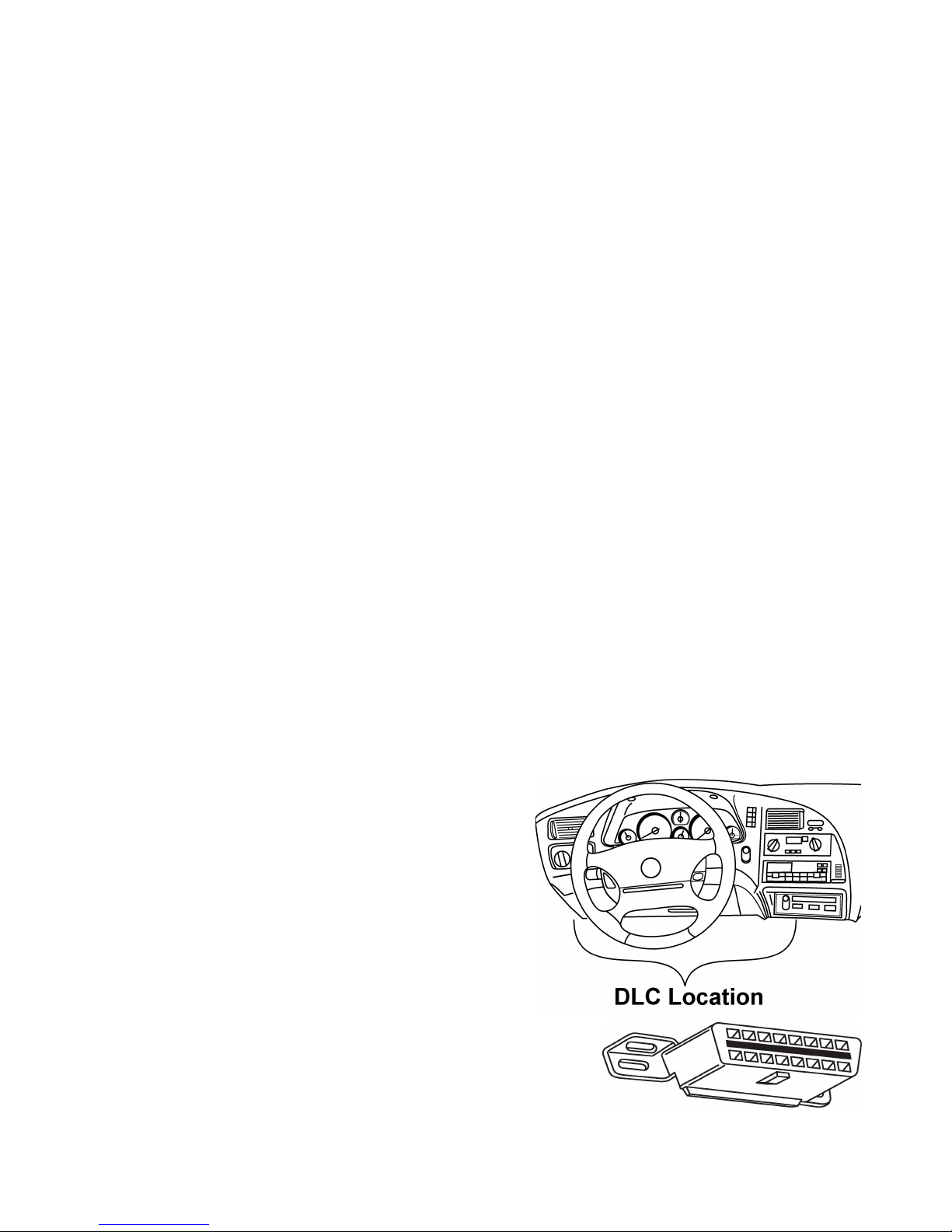
1-3 Diagnostic Connector and Location
The OBD II System Tester communicates with
the vehicle via a diagnostic link connector (DLC).
OBD II S ecification J1962 defines the DLCs
hysical and electrical ro erties. The DLC is
known as the J1962 connector. The S ecification
J1962 was introduced by the SAE (Society of
Automotive Engineers) to make all com liant
vehicles use the same DLC with the generic link
information available on the same ins, no
matter what make of vehicle. In addition to the
connector s ecification, there is a guideline on
where to locate the DLC or J1962 connector, which
states it should be located under the dashboard on the
drivers side of the vehicle. Even with this guideline, not
all OBD II DLCs are located under the dash on the
drivers side. If the DLC is not located in the s ecified area, then a note will be laced
where the DLC should be informing the user of the location. If you cannot find the
DLC, see the vehicle service documentation for its location.