KALATEL CBR-KB3 User manual

Installation and Operation Manual
Revision B 0150-0133
CBR-KB3
and
CBR-KB3/J
Remote Keyboards
Installation and Operation
Manual
925
13 29
521
117
1026
1430
622
218
1127
1531
723
319
12 28
16 32
824
420
ALT
{ }
F
BC D E
AUX2AUX1 AUX3 AUX4
#
925
1329
521
117
1026
1430
622
218
11 27
15 31
723
319
12 28
16 32
824
420
ALT
{ }
F
BC D E
AUX2AUX1 AUX3 AUX4
#

Installation and Operation Manual
0150-0133 ii Revision B
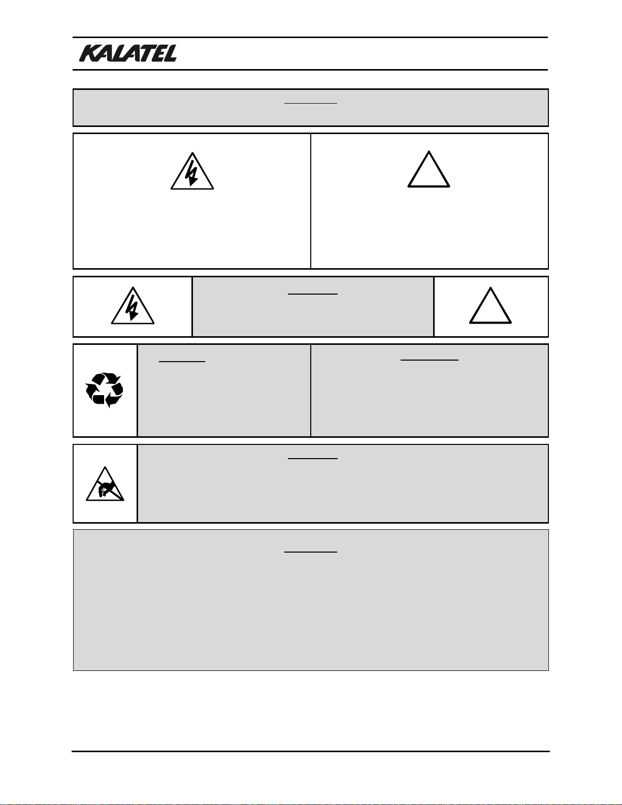
WARNING!
To prevent fire and electric shock, do not expose this product to rain or moisture.
The lightning flash with the arrowhead symbol,
within an equilateral triangle, is intended to alert
the user to the presence of uninsulated
"dangerous voltage" within the products enclosure
that maybe of sufficient magnitude to constitute a
risk of electric shock to persons.
!
The exclamation point, within an equilateral
triangle, is intended to alert the user to the
presence of important operating and maintenance
(servicing) instructions in the literature
accompanying the product.
CAUTION!
To prevent electric shock do not remove cover. No
user serviceable components inside. Refer
servicing to qualified service personnel. !
CAUTION! Lithium Battery
Danger of explosion if battery is
incorrectly replaced. Replace only
with the same or equivalent type
recommended by the manufacturer.
ATTENTION
This product contains a lithium battery. This
battery may be recyclable. It may be illegal to
dispose of this battery improperly under local,
state, or federal laws. Check with a local waste
management official for disposal and recycling
options.
CAUTION!
Electrostatic-Sensitive Device!
Use proper CMOS and MOSFET handling precautions, including approved
grounded wrists straps, etc., to avoid damage to this unit or its internal
components, from electric discharge.
WARNING!
This equipment generates, uses and can radiate radio frequency energy and if not installed and used in
accordance with the instructions in this manual, may cause interference to radio communications. It
has been tested and found to comply with the limits for a Class A computing device pursuant to subpart
J of part 15 of FCC rules which are designed to provide reasonable protection against such
interference when operated in a commercial environment. This equipment has also been tested and
found to comply with the requirements for a CE Class A device and TUV safety standards.
Operation of this equipment in a residential area may cause interference, in which case the user is a
required to take all measures that are necessary, at the user's expense, to correct the interference.

Installation and Operation Manual
Revision B iii 0150-0133
IMPORTANT INFORMATION
Software and/or firmware is furnished to the purchaser under a license for use on a single system.
Software and/or firmware included with this equipment are the sole proprietary property of, confidential
to, and copyrighted by Kalatel, Corvallis, Oregon, USA. The software/firmware are not to be copied or
disclosed in any manner without the express written consent of Kalatel.
NOTE: All information and specifications furnished by Kalatel are believed to be
accurate and reliable. But, Kalatel assumes no responsibility for neither its use
nor any infringements of rights of third parties that may result from its use. No
license is granted by implication or otherwise under any patent or patent rights
of Kalatel.
The CALIBUR™brand name and product model numbers are the property of Kalatel.
COPYRIGHT, 2000: The contents of this manual may not be copied or reproduced in any manner or
form without the prior written consent of Kalatel.

Installation and Operation Manual
0150-0133 iv Revision B
This page intentionally left blank

Installation and Operation Manual
Revision B v0150-0133
Contents
1IMPORTANT SAFEGUARDS ....................................................................... 1-1
2INITIAL CONSIDERATIONS ........................................................................ 2-1
2.1 Product Description.........................................................................................2-1
2.2 Installation Site Considerations .....................................................................2-1
3CONTROLS AND INDICATORS ................................................................... 3-1
Model CBR-KB3 Keyboard ......................................................................................3-1
3.2 Model CBR-KB3/J Keyboard...........................................................................3-1
3.3 LCD Display Description.................................................................................3-2
3.4 Common Equipment Controls........................................................................3-2
3.5 The ALT Key.....................................................................................................3-3
3.6 Device-Specific Controls.................................................................................3-4
4WIRING AND CONNECTIONS..................................................................... 4-1
4.1 System Wiring Diagrams.................................................................................4-1
4.2 Start-Up.............................................................................................................4-3
4.3 The RS-485 Network........................................................................................4-3
4.4 The RS-422 Network........................................................................................4-4
5KEYBOARD OPERATIONS......................................................................... 5-1
5.1 CBR-KB3 States...............................................................................................5-1
5.2 Multiplexer Interfacing.....................................................................................5-1
5.3 Network Interfacing .........................................................................................5-4
5.4 Other Available Keyboard Functions.............................................................5-5
5.5 Kalatel CyberDome Programming..................................................................5-8
6SPECIFICATIONS ..................................................................................... 6-1
7SERVICE AND WARRANTY........................................................................ 7-1

Installation and Operation Manual
0150-0133 vi Revision B
This page intentionally left blank

Installation and Operation Manual
Revision B 1-1 0150-0133
1IMPORTANT SAFEGUARDS
Read Instructions
Read all the safety and operating instructions before operating the unit.
Retain instructions
Retain the safety and operating instructions for future reference.
Heed Warnings
Observe all the warnings on the unit and in the operating instructions.
Follow Instructions
Follow all operation/use instructions.
Cleaning
Unplug the unit from the power outlet before cleaning. Do not use liquid cleaners or aerosol cleaners.
Use a damp cloth for cleaning.
Attachments
Do not use attachments not recommended by the product manufacturer. They might cause hazards.
Use only with accessories recommended by the manufacturer or sold with the product.
Water and Moisture
Do not use this unit near water. For example:
•Near a bathtub, wash bowl, kitchen sink, or laundry tub.
•In a wet basement.
•Near a swimming pool.
•In an unprotected outdoor installation.
•In any area classified as a wet location.
Accessories
Do not place this unit on an unstable stand, tripod, bracket, or mount. The unit might fall, causing
serious injury to a person and serious damage to the unit.
Any mounting of the unit should follow the manufacturer's instructions, and should use a mounting
accessory recommended by the manufacturer.

Installation and Operation Manual
0150-0133 1-2 Revision B
Ventilation
Openings in the enclosure, if any, are provided for ventilation and to ensure reliable operation of the
unit and to protect it from overheating. These openings must not be blocked or covered.
This unit should not be placed in a built-in installation unless proper ventilation is provided. Do not
place directly on other hot equipment that may increase its operating temperature.
Power Sources
This unit should be operated only from the type of power source indicated on the marking label. If
unsure of the type of power supply to use, consult an appliance dealer or a local power company.
For units intended to operate from battery power or other sources, refer to the operating instructions.
Grounding and Polarization
This unit may be equipped with a polarized AC line plug having one blade wider than the other. This
plug fits into the power outlet in only one way.
This is a safety feature. If unable to insert the plug fully into the outlet, try reversing the plug. If the
plug still fails to fit, contact an electrician to replace the outlet.
Do not defeat the safety purpose of the polarized plug.
Alternatively, this unit may be equipped with a three-wire grounding-type plug (a plug having a third pin
for grounding). This plug fits only a grounding-type power outlet.
This is a safety feature. If unable to insert the plug into the outlet, contact an electrician to replace the
outlet.
Do not defeat the safety purpose of the grounding-type plug.
Power Cord Protection
Power cords should be routed so that they are not likely to be walked on or pinched by items placed
upon or against them.
Pay particular attention to cords at plugs, convenience receptacles, and the point where they exit from
the appliance.
Power Lines
An outdoor system should not be located near overhead power lines (or other electric light or power
circuits), or where it might fall into such power lines or circuits.
When installing an outdoor system, take extreme care not to touch power lines or circuits. Contact
with them might be fatal.
Overloading
Do not overload outlets and extension cords. This can result in a risk of fire or electric shock.
Object and Liquid Entry
Never push objects of any kind into this unit through openings. They might touch dangerous voltage
points or cause short circuits, possibly resulting in a fire or electric shock.
Never spill liquid of any kind on the unit.

Installation and Operation Manual
Revision B 1-3 0150-0133
Adjustments
If the unit does not operate normally by following the operating instructions:
•Adjust only those controls that are covered by the operating instructions.
•Improper adjustment of other controls may result in damage, or void the warranty, and often
requires extensive work by a qualified technician to correct.
Servicing
Do not attempt to service this unit. Opening or removing covers may expose dangerous voltage or
other hazards. Refer all servicing to qualified service personnel.
Damage Requiring Service
Unplug the unit from the outlet and refer servicing to qualified service personnel under the following
conditions:
•When the power-supply cord or plug is damaged.
•If liquid has been spilled, or objects have fallen into the unit.
•If the unit has been exposed to rain or water.
•If the unit has been dropped or the cabinet has been damaged.
•When the unit exhibits a distinct change in performance, this indicates a need for service.
Replacement Parts
When replacement parts are required, be sure the service technician has used parts specified by the
manufacturer, or that they have the same characteristics. Unauthorized substitutions may result in
fire, electric shock, or other hazards.
Safety Check
Upon completion of any service or repairs to this unit, ask the service technician to perform safety
checks to determine that the unit is in proper operating condition.
Coaxial Cable Grounding
If an outside cable system is connected to the unit, be sure the cable system is grounded.
Lightning
For added protection of this unit during a lightning storm, or when it is left unattended and unused for
long periods, unplug it from the wall outlet and disconnect the cable system. This can prevent damage
to the unit due to lightning and power-line surges.

Installation and Operation Manual
0150-0133 1-4 Revision B
This page intentionally left blank

Installation and Operation Manual
Revision B 2-1 0150-0133
2INITIAL CONSIDERATIONS
2.1 Product Description
The CBR-KB3 series of remote keyboards are accessories for the Calibur 10, and 16 channel range of
multiplexers as well as the MMX (multiplexer / matrix) units and DVMR (digital video multiplexer /
recorder) units. It allows the user to set up a centrally controlled system of up to 32 devices, with
telemetry controlled (PTZ) cameras.
A CBR-KB3 keyboard can control up to 31 Calibur multiplexers and up to 992 telemetry cameras.
Multiple keyboards can be used on the same network, allowing multiple operators to control the same
set of multiplexers and telemetry cameras.
The CBR-KB3 network is based on industry standard RS-422 and RS-485 communications links, and
so, simple cabling and extended distances between devices is standard.
The CBR-KB3 remote keyboard is housed in a rugged desktop enclosure with a full tactile feedback
elastomeric keypad. A joystick version (the CBR-KB3/J) is also available and supports the use of
variable speed telemetry systems. Contact a distributor for current equipment compatibility.
2.2 Installation Site Considerations
AC Power
Ensure that the AC power supply to which the external DC power supply is connected is stable,
and is within 10% of the rated voltage.
If the power source is likely to have excessive spikes or power dips, power line conditioning, or a
UPS should be considered, to avoid possible power resets or damage to the unit.
Ventilation
Ensure that the location planned for the installation of the unit is well ventilated.
Take note of the locations of the cooling vents in the unit’s enclosure, and ensure that they are not
obstructed in the planned installation.
Temperature
Observe the unit’s ambient temperature specifications when choosing an installation site.
Extremes of heat or cold beyond the specified operating temperature limits may cause the unit to
fail or to be damaged.
Other Equipment
Do not install the unit in cabinets with, or immediately above, or adjacent to equipment that may
cause ambient temperatures around the unit to exceed the operating temperature limits for the
unit.
Table 2-1. Installation Site Considerations.

Installation and Operation Manual
0150-0133 2-2 Revision B
This page intentionally left blank

Installation and Operation Manual
Revision B 3-1 0150-0133
3CONTROLS AND INDICATORS
3.1 Model CBR-KB3 Keyboard
3.2 Model CBR-KB3/J Keyboard
ENTER
MENU
FRAME
FORWARD
STOP
FRAME
REVERSE
FAST
FORWARD
SEARCH
FAST
REVERSE
ZOOM
(optical) FOCUS
IRIS JOYSTICK
UNIT
SELECT
PRESETS
GLOBAL
AUXILLIARY
KEYS 1-4
TELEMETRY
ON/OFF
SHIFT
LCD
DISPLAY
CAMERA
KEYS
RECORD PLAY
LIVE
ALT
MONITOR-A
(multiscreen) MONITOR-B
MONITOR-C MONITOR-DMONITOR-EFREEZE SEQUENCE FUNCTION
2X-ZOOM ALARM
925
13 29
521
117
10 26
14 30
622
218
11 27
15 31
723
319
12 28
16 32
824
420
ALT
{ }
F
BC D E
AUX2AUX1 AUX3 AUX4
#
925
13 29
521
117
10 26
14 30
622
218
11 27
15 31
723
319
12 28
16 32
824
420
ALT
{ }
F
BC D E
AUX2AUX1 AUX3 AUX4
#
ENTER
MENU
FRAME
FORWARD
STOP
FRAME
REVERSE
FAST
FORWARD
SEARCH
FAST
REVERSE
ZOOM
(optical) FOCUS
IRIS ARROWS
UNIT
SELECT
PRESETS
GLOBAL
AUXILLIARY
KEYS 1-4
TELEMETRY
ON/OFF
SHIFT
LCD
DISPLAY
CAMERA
KEYS
RECORD PLAY
LIVE
ALT
MONITOR-A
(multiscreen) MONITOR-B
MONITOR-C MONITOR-DMONITOR-EFREEZE SEQUENCE FUNCTION
2X-ZOOM ALARM

Installation and Operation Manual
0150-0133 3-2 Revision B
3.3 LCD Display Description
Top line - Key descriptions, messages
and ‘Connected / Standing By’ text.
Bottom line - CC (SS | DD)
CC Currently selected camera number (1-32).
SS The CBR-KB3's network ID number (1-32).
DD The network ID of the multiplexer to which the CBR-KB3 is connected (Range: 1-32).
While there is no connection, DD is displayed as ??
Table 3-1. LCD Display Description (see the rectangular diagram above).
3.4 Common Equipment Controls
Common Controls
NOTE: These keys are used with all types of multiplexers and special equipment.
UNIT SELECT Selects multiplexer to be controlled or to be released from control. Also sets
keyboard network address, monitor mode and silences keyboard buzzer.
LCD DISPLAY Shows unit status and operator prompts.
RECORD Selects RECORD mode. (Duplex models are always in record mode; key is inactive).
Indicator: LED above key.
PLAY Selects playback mode for decoding tapes. Indicator: LED above key.
LIVE Selects LIVE mode. Indicator: LED above key.
MON-A Selects Multiscreen display if in full-screen. If in multiscreen, switches to next
multiscreen.
MON-B Sets keys to act on MON-B (Spot) only. Indicator: LED above key.
FREEZE Freezes any display in LIVE or PLAY mode. In the Telemetry Mode, functions as
PREVIOUS key in Kalatel Dome programming.
Table 3-2. Common Controls (see the diagram above).

Installation and Operation Manual
Revision B 3-3 0150-0133
Common Controls
ALARM Used to accept active alarms. Indicator: Flashing LED above key. Used to
accept active alarms. Indicator: Flashing LED above key. In the Telemetry Mode,
functions as the HELP key in the Kalatel Dome Menu.
SEQUENCE Starts/Stops sequencing on MON-A or MON-B, C, D and E. On MON-A, operates
on full-screen or last cameo of any multiscreen. In the Telemetry Mode, functions
as the NEXT key in Kalatel Dome Menu.
2X ZOOM Digital. Zooms 2X on full-screen displays. During zoom, arrow keys pan and tilt.
Indicator: LED above key.
FUNCTION (Macro) Starts execution of a pre-recorded macro. Used with camera, PLAY, and
SEQ keys.
CAMERAs Used to select full-screen displays of cameras. Also used with FUNCTION key,
and telemetry. In the Telemetry Mode, the 10 key is used for inputting a zero in the
Kalatel Dome Menu.
ARROWs Used in MENUs, and for pan and tilt in 2X Zoom. Also used with telemetry for
camera control of pan/tilt/zoom functions.
JOYSTICK Used in MENUs, and for pan and tilt in 2X Zoom. Also used with telemetry for
camera control of pan/tilt/zoom functions. Joystick option with variable speed
P/T/Z control is supported.
MENU MENU Setup. Used to enter menus, and to escape from menus at any time. In
the Telemetry Mode, activates the Kalatel Dome Programming.
ENTER/SELECT Used in menus to select and enter options. Selects Active Cameo mode.
Indicator: LED above key.
SHIFT KEY If selected, (LED ON), then other keys have SHIFTed functions. Used with AUX
1-4 to select AUX 5-8, and camera buttons to select device network addresses
above 16.
GLOBAL Used to poll network to determine what equipment is connected to it. Also used to
send a command (for example, Preset 1) to all cameras.
Table 3-2. Common Controls (see diagram on page 3-2).
3.5 The ALT Key
NOTE: Appears only on Triplex, MMX and is also used when working with Kalatel
dome presets.
ALT KEY If selected, (LED ON), then selected other keys have alternate functions. Used
with camera keys to select cameras, or presets 17-32, and with the VCR control
sub-macro functions.
Table 3-3. The ALT KEY (see diagram on page 3-2).

Installation and Operation Manual
0150-0133 3-4 Revision B
3.6 Device-Specific Controls
Matrix/Multiplexer Controls
NOTE: These keys are used only with the Matrix/Multiplexer (MMX) units.
MON-C Sets keys to act on MON-C (Spot) only. Indicator: LED above key.
MON-D Sets keys to act on MON-D (Spot) only. Indicator: LED above key.
MON-E Sets keys to act on MON-E (Spot) only. Indicator: LED above key.
Table 3-5. The Matrix/Multiplexer Controls (see diagram on page 3-2).
Digital HDD Controls
NOTE: These keys are used only with the Digital Hard Disk recorder and multiplexer.
SEARCH Used with Hard Disk multiplexer and recorder for locating video on the Hard
Disk or an Archive DAT tape drive.
FAST FORWARD Used to speed up the playback and for searching the Hard Disk.
FAST REVERSE Used for reverse playback, searching the Hard Disk, and Rewind operations.
FRAME FORWARD Used when the FREEZE control is activated in playback for single frame
advance playback.
FRAME REVERSE Used when the FREEZE control is activated in playback for single frame
reverse playback.
STOP Used to halt playback operations.
Table 3-6. The Digital HDD Controls (see diagram on page 3-2).
Telemetry Controls
NOTE: Telemetry keys used only with P/T/Z cameras and are Receiver/Driver type
dependent.

Installation and Operation Manual
Revision B 3-5 0150-0133
TELEMETRY ON / OFF. Must be ON to use telemetry keys. Telemetry operates on
selected camera only. Indicator: LED above key.
AUX 1 - 4, AUX 5 - 8 Control of receiver/driver relays and related functions. If SHIFT is on, then
becomes AUX 5-8. Indicators: LEDs above keys. See the additional
details following this table.
PRESETS Used to set and recall presets.
FOCUS Used to focus in or focus out.
IRIS Used to open and close iris.
ZOOM (Optical) Zooms camera lens in or out.
PAN and TILT (Arrow keys and joystick.) Pans and tilts selected camera.
Table 3-7. Telemetry Controls (see diagram on page 3-2).
Special Features (AUX button controls)
Special features are available for the AUX buttons when using telemetry receivers from selected
manufacturers. The Calibur ProBridge manuals cover these variations for what the AUX buttons
control when not using Kalatel telemetry equipment.
Special features are available when using the Kalatel Mini-Dome. The following table lists the
functions for these keys:
Auxiliary Function Kalatel MIni-Dome Function
AUX 1 •Start Tour number one (Each push will turn ON Tour
number one, regardless of LED status).
AUX 2 •Activate Auto-Focus (One push will turn ON Auto-
Focus, regardless of LED status).
AUX 3 •Speed Level 0.
AUX 4 •Speed Level 1.
AUX 5 •• Set Autopan Limits (Toggle: ON for Left Limit/OFF for
Right Limit).
AUX 6 •• Start Autopan (ON/OFF).
AUX 7 •• Press and hold AUX7: Gate Open start.
Release Aux7: Gate Open stop.
AUX 8 •• Press and hold Aux8: Gate Close start.
Release Aux8: Gate Close stop.
•Requires the SHIFT key to be OFF (Shift LED is OFF).
•• Requires the SHIFT key to be ON (Shift LED is ON).
Table 3-8. Special Features on the Kalatel Mini-Dome.

Installation and Operation Manual
0150-0133 3-6 Revision B
The AUX 1 Key
This feature is used for commanding the CyberDome to activate tour number one. Each time the key
is pressed tour number one will start, regardless of the AUX 1 LED status, or previous setting. The
LED indicator does not indicate that a tour is active or inactive.
The AUX 2 Key
This feature is used for activating the Auto-Focus setting by pushing the AUX 2key. One push will turn
ON the Auto-Focus feature, regardless of the AUX 2 LED status, or previous setting. The LED
indicator does not indicate that Auto-Focus is active or inactive.
The AUX 3 and AUX 4 Keys
This feature is used on keypads not having a joystick. Pushing the AUX 3 and AUX 4 keys will give
the different settings in the table below:
Setting Speed Levels AUX 3 AUX 4
Slowest Speed OFF OFF
Slow Speed ON OFF
Fast Speed OFF ON
Fastest Speed ON ON
Table 3-9. The AUX 3 and AUX 4 Keys.
The AUX 5 Key
This feature is used for setting the Autopan Limits by pushing the AUX 5 key. Toggling the AUX 5 key
will set the Left/Right Limits as follows:
1. Set the left limit by using the joystick or the arrow key.
2. Turn ON the AUX 5 key.
3. Set the right limit using the joystick or the arrow key.
4. Turn OFF the AUX 5 key.
The AUX 6 Key
This feature is used for setting the Autopan by pushing the AUX 6 key. Toggling the AUX 6 key will
set Autopan ON/OFF.
The AUX 7 and AUX 8 Keys
This feature is used for Opening/Closing the gate by pressing the AUX 7 and AUX 8 keys as follows:
1. When the AUX 7 key is pressed, the gate starts to Open.
2. When the AUX 7 key is released, the gate stops moving.
3. When the AUX 8 key is pressed, the gate starts to Close.
4. When the AUX 8 key is released, the gate stops moving.

Installation and Operation Manual
Revision B 4-1 0150-0133
4WIRING AND CONNECTIONS
The following diagram shows the wiring configuration when connected to Kalatel telemetry equipment. A
Calibur ProBridge is required when connected to selected other manufacturers equipment, Wiring and
operation for these other devices is discussed in the specific ProBridge manual for that manufacturer.
4.1 System Wiring Diagrams
RJ-45 Connectors
12Vdc
power
adapter
12Vdc
power
adapter
CBR-KB3
Kalatel
Mini-Dome
Calibur CBR, MMX and DVMR
series video equipment
12Vdc power
adapter
24Vac
power
adapter
1 2 3 4 5 6 7 8 9 10 11 12 13 14 15 16
RS-232
1 RS-485 2 12VDC
B
2-wire twisted
unshielded
BLKRED
Interface
Connector
Card
(Supplied)
RJ-45 Connector
12VDC RS-422 1 PWR 2
RS-485 12VDC RS-422 1 PWR 2
RS-485
RS-422 Cable:
RJ-45 to RJ-45
(Supplied)
WHT/
GRY
BRN
YEL
GRN BLK
ORG
BLU
red
blk
8
7
6
5
1
2
3
4
Remote Keypad
2-wire twisted
unshielded
RS-485 Cables:
RJ-45 to RJ-45
(Supplied)
CBR-KB3/J
RED
14 Vdc POS (+)
DTMF-A
Terminal
RS-422 (Out B)
RS-422 (IN A)
Kalatel
Terminal Block Wiring
RS-422 (IN B)
RS-422 (Out A)
14 Vdc NEG (-)
DTMF-B
Signal
8
7
6
5
1
2
3
4
Terminal Block
(Supplied)
(Supplied)
Remote Keypad
(Supplied) Configuration Note:
This wiring method should be used when no
other KTD series equipment will be used in the
system.
Video Signal
Coaxial Cable
Non-Digiplex Applications

Installation and Operation Manual
0150-0133 4-2 Revision B
Digiplex Applications
RJ-45 Connectors
12Vdc
power
adapter
Kalatel
Mini-Dome
12Vdc power
adapter
24Vac
power
adapter
12345678 9 10 11 12 13 14 15 16
RS-232
1 RS-485 2 12VDC
B
2-wire twisted
unshielded
BLKRED
To other Calibur
RS-485 devices
12VDC RS-422 1 PWR 2
RS-485
RS-422 Cable:
RJ-45 to RJ-45
(Supplied with KTD-304)
WHT/
GRY
BRN
YEL
GRN
BLK neg (-)
ORG
BLU
red
blk
8
7
6
5
1
2
3
4
Remote Keypad
RS-485 Cables:
RJ-45 to RJ-45
(Supplied)
CBR-KB3/J
RED pos (+)
14 Vdc POS (+)
DTMF-A
Terminal
RS-422 (Out B)
RS-422 (IN A)
Kalatel
Terminal Block Wiring
RS-422 (IN B)
RS-422 (Out A)
14 Vdc NEG (-)
DTMF-B
Signal
8
7
6
5
1
2
3
4
Terminal Block
(Supplied)
(Supplied)
Configuration Note:
This wiring method should be used when
other Digiplex equipment will be used in the
system. Depending on your configuration, a
KTD-312 data merger may also be required.
red
blk
(blk) 2 1 (red)
RS-422 Cable:
RJ-45 to
flying leads
(User Supplied)
14Vdc
power
adapter
(Supplied)
KTD-304
Remote
Keypad
Video Signal
Coaxial Cable
Interface
Connector
Card
(Supplied)
Calibur CBR, MMX and DVMR
series video equipment
Before starting a telemetry connection, and connecting other optional accessory equipment to the
system, make sure the multiplexer, power, video, VCR, and monitor connections are completed, and
everything is working correctly.
Pre-wire the telemetry equipment according to the manufacturer’s instructions and specifications. Use
the internal diagnostic testing capabilities of the telemetry receiver (if any) to verify that the power and
the connections to the lens and motors are correct and functioning properly.
Also carefully and completely read the manuals for each piece of equipment before attempting to
install and connect the equipment.
Although the multiplexer is capable of powering a single keypad from the multiplexer internal power,
Kalatel recommends that the external power adapter, supplied with the unit, always be used. The
provision to supply power to the single keypad is intended for demonstration purposes only.
This manual suits for next models
1
Table of contents
Popular Musical Instrument manuals by other brands

Rodgers Organ Company
Rodgers Organ Company 32B owner's manual

Hemingway
Hemingway DP-501 MK II user manual

KEYSWERK
KEYSWERK BOHM SEMPRA SE20 operating instructions

Roland
Roland RD-700NX Turbostart

Yamaha
Yamaha Clavinova CLP-153SG Mode d'emploi

Baldwin Piano & Organ Company
Baldwin Piano & Organ Company FunMachine 121 Technical manual