Kalley K-LED40FHDZT2 User manual

LCD Television
KALLEY
Service Manual
Chassis:9206B
Product:
Ver 1.0
May , 2015
K-LED40FHDZT2

- 2 -
Content
Content ...................................................................................................................................................................- 2 -
Service Manual ......................................................................................................................................................- 3 -
1. Precautions and notices................................................................................................................................- 3 -
1.1 Warning..............................................................................................................................................- 4 -
1.2 Notes..................................................................................................................................................- 7 -
2. Product Specifications ...............................................................................................................................- 10 -
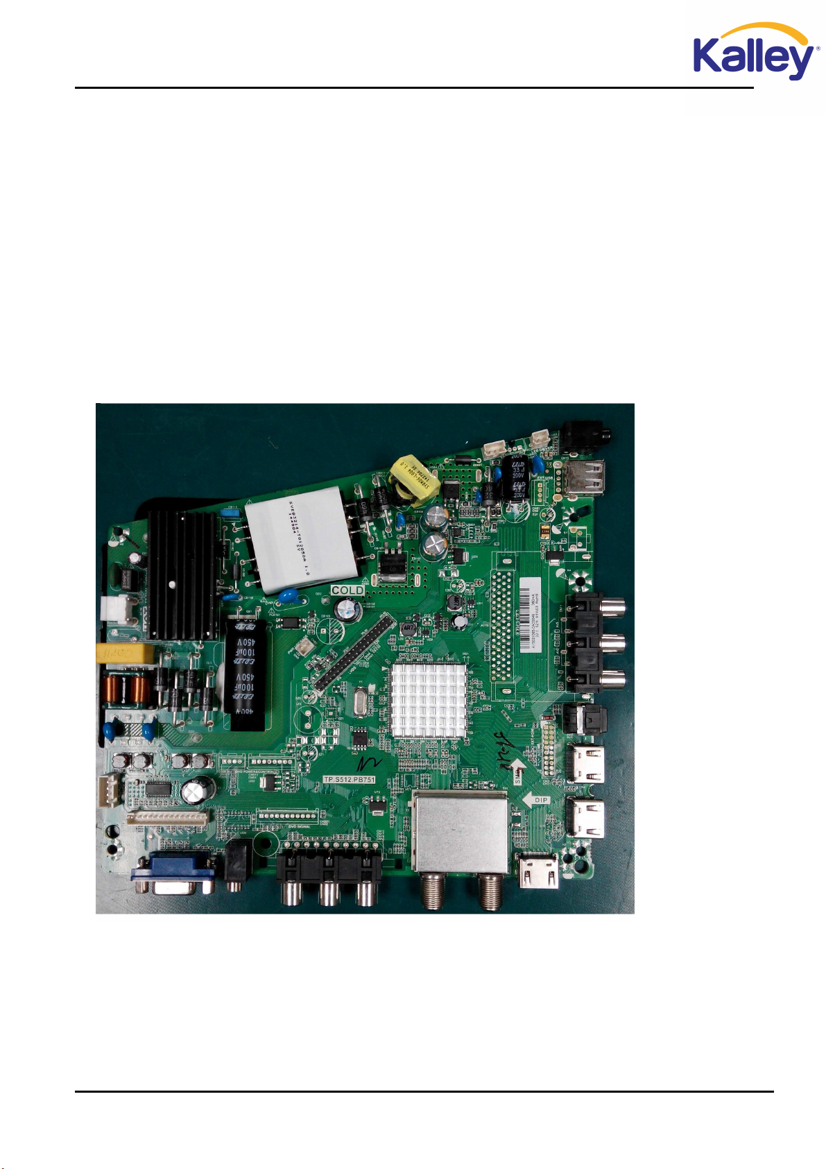
2.1 Main board layout............................................................................................................................- 10 -
2.2 The service manual Includes products.............................................................................................- 11 -
2.3 TV Front and Rear ...........................................................................................................................- 11 -
3. Factory/Service OSD Menu and Adjustment.............................................................................................- 18 -
3.1 How to enter the Factory OSD Menu ..............................................................................................- 18 -
3.2 Factory OSD Menu..........................................................................................................................- 18 -
4. Software updating......................................................................................................................................- 21 -
4.1 USB upgrade....................................................................................................................................- 21 -
4.2 SIS Tool upgrade .............................................................................................................................- 22 -
5.Trouble shooting .........................................................................................................................................- 27 -
6. Circuit instruction ......................................................................................................................................- 33 -
Power assign and Main board signal process ........................................................................................- 33 -
7. Schematic circuit diagram .........................................................................................................................- 35 -
8. Explode View.............................................................................................................................................- 35 -

- 3 -
Service Manual
1. Precautions and notices
BEFORE SERVICING THE LCD TV, READ THE SAFETY PRECAUTIONS IN
THIS MANUAL.
WHEN REPLACEMENT PARTS ARE REQUIRED, BE SURE TO USE
REPLACEMENT PARTS SPECIFIED BY THE MANUFACTURER.
Proper service and repair is important to the safe, reliable operation of all Hisense
Electric Co., Ltd Equipment. The service procedures recommended by Hisense and
described in this Service Guide are effective methods of performing service operations.
Some of service
operations require the use of tools specially designed for the purpose. The special tools
should be used when and as recommended.
It is important to note that this manual contains various CAUTIONS and NOTICES
which should be carefully read in order to minimize the risk of personal injury to
service personnel. The possibility exists that improper service methods may damage
the equipment. It is also important to understand that these CAUTIONS and
NOTICES ARE NOT EXHAUSTIVE. Hisense could not possibly know, evaluate and
advise the service trade of all conceivable ways in which service might be done or of
the possible hazardous consequences of each way. Consequently, Hisense has not

- 4 -
undertaken any such broad evaluation. Accordingly, a serviceman that uses a service
procedure or tools, which are not recommended by Hisense, must first satisfy himself
thoroughly that neither his safety nor the safe of the equipment
will be jeopardized by the service method selected.
Hereafter throughout this manual, Hisense Electric Co., Ltd will be referred to as
Hisense.
1.1 Warning
1.1.1
Critical components having special safety characteristics are identified with a by
the Ref. No. in the parts list. Use of substitute replacement parts, which do not have
the same specified safety characteristics, may create shock, fire, or other hazards.
Under no circumstances should the original design be modified or altered without
written permission from Hisense. Hisense assumes no liability, express or implied,
arising out of any unauthorized modification of design. Serviceman assumes all
liability.
1.1.2.
DANGER CAUTION
TO ENSURE THE CONTINUED RELIABILITY OF THIS PRODUCT, USE ONLY
ORIGINAL MANUFACTURER'S REPLACEMENT PARTS, WHICH ARE LISTED WITH
THEIR PART NUMBERS IN THE PARTS LIST SECTION OF THIS SERVICE GUIDE.

- 5 -
All ICs and many other semiconductors are susceptible to electrostatic discharges
(ESD). Careless handling during repair can reduce life drastically. When repairing,
make sure that
you are connected with the same potential as the mass of the set by a wristband with
resistance. Keep components and tools also at this same potential.
1. Never replace modules or other components while the unit is switched on.
2. When making settings, use plastic rather than metal tools. This will prevent
any short circuits and the danger of a circuit becoming unstable.
1.1.3
To prevent electrical shock, do not use this polarized ac plug with an extension cord,
receptacle, or the outlet unless the blades can be fully inserted to prevent blade
exposure.
To prevent electrical shock, match wide blade or plug to wide slot, fully insert.
1.1.4
When replacement parts are required, be sure to use replacement parts specified by the
manufacturer or have the same characteristics as the original part. Unauthorized
substitutions may result in fire, electric shock, or other hazards.
1.1.5
Safety regulations require that after a repair the set must be returned in its original
condition. In particular attention should be paid to the following points.
-Note: The wire trees should be routed correctly and fixed with the mounted

- 6 -
cable clamps.
-The insulation of the mains lead should be checked for external damage.
1.1.6
(1) Do not touch Signal and Power Connector while this product operates. Do not
touch EMI ground part and Heat Sink of Film Filter.
(2) Do not supply a voltage higher than that specified to this product. This may
damage the product and may cause a fire.
(3) Do not use this product in locations where the humidity is extremely high, where
it may be splashed with water, or where flammable materials surround it. Do not
install or use the product in a location that does no satisfy the specified
environmental conditions. This may damage the product and may cause a fire.
(4) If a foreign substance (such as water, metal, or liquid) gets inside the panel
module, immediately turn off the power. Continuing to use the product may cause
fire or electric shock.
(5) If the product emits smoke, and abnormal smell, or makes an abnormal sound,
immediately turn off the power. Continuing to use the product, it may cause fire or
electric shock.
(6) Do not disconnect or connect the connector while power to the product is on. It
takes some time for the voltage to drop to a sufficiently low level after the power has
been turned off. Confirm that the voltage has dropped to a safe level before
disconnecting or connecting the connector.

- 7 -
(7) Do not pull out or insert the power cable from/to an outlet with wet hands. It may
cause electric shock.
(8) Do not damage or modify the power cable. It may cause fire or electric shock.
(9) If the power cable is damaged, or if the connector is loose, do not use the product:
otherwise, this can lead to fire or electric shock.
(10) If the power connector or the connector of the power cable becomes dirty or
dusty, wipe it with a dry cloth. Otherwise, this can lead to fire.
(11) Use only with the cart, stand, tripod, bracket, or table specified by the
manufacturer, or sold with the apparatus. When a cart is used, use caution when
moving the cart/apparatus combination to avoid injury from tip-over.
1.2 Notes
Notes on Safe Handling of the LCD panel and during service
The work procedures shown with the Note indication are important for ensuring the
safety of the product and the servicing work. Be sure to follow these instructions.
• Before starting the work, secure a sufficient working space.
• At all times other than when adjusting and checking the product, be sure to turn OFF
the POWER Button and disconnect the power cable from the power source of the TV
during servicing.
• To prevent electric shock and breakage of PC board, start the servicing work at least
30 seconds after the main power has been turned off. Especially when installing and

- 8 -
removing
the power board, start servicing at least 2 minutes after the main power has been
turned off.
• While the main power is on, do not touch any parts or circuits other than the ones
specified.
If any connection other than the one specified is made between the measuring
equipment and the high voltage power supply block, it can result in electric shock or
activation of the leakage-detection circuit breaker.
• When installing the LCD module in, and removing it from the packing carton, be
sure to have at least two persons perform the work.
• When the surface of the panel comes into contact with the cushioning materials, be
sure to confirm that there is no foreign matter on top of the cushioning materials
before the surface of the panel comes into contact with the cushioning materials.
Failure to observe this precaution may result in, the surface of the panel being
scratched by foreign matter.
• When handling the circuit board, be sure to remove static electricity from your body
before handling the circuit board.
• Be sure to handle the circuit board by holding the large parts as the heat sink or
transformer. Failure to observe this precaution may result in the occurrence of an
abnormality in the soldered areas.
• Do not stack the circuit boards. Failure to observe this precaution may result in

- 9 -
problems resulting from scratches on the parts, the deformation of parts, and
short-circuits due to residual electric charge.
• Routing of the wires and fixing them in position must be done in accordance with the
original routing and fixing configuration when servicing is completed. All the wires
are routed far away from the areas that become hot (such as the heat sink). These wires
are fixed in position with the wire clamps so that the wires do not move, thereby
ensuring that they are not damaged and their materials do not deteriorate over long
periods of time. Therefore, route the cables and fix the cables to the original position
and states using the wire clamps.
• Perform a safety check when servicing is completed. Verify that the peripherals of
the serviced points have not undergone any deterioration during servicing. Also verify
that the screws, parts and cables removed for servicing purposes have all been
returned to their proper locations in accordance with the original setup.
The lightning flash with arrowhead symbol, within an equilateral
triangle is intended to alert the user to the presence of uninsulated
dangerous voltage within the products enclosure that may be of sufficient magnitude
to constitute a risk of electric shock.
The exclamation point within an equilateral triangle is intended to
alert the user to the presence of important operating and maintenance
(servicing) instructions in the literature accompanying the set.

- 10 -
2. Product Specifications
2.1 Main board layout
2.1.1
LHD32D50TAM andLTDN40D50TAM use CVTE board: TP.S512.PB751\ROH

- 11 -
TV Front

- 12 -
TV Back

- 15 -

- 17 -
2.4 Remote control

- 18 -
3. Factory/Service OSD Menu and Adjustment
3.1 How to enter the Factory OSD Menu
With user’s RC
Power on the TV.
1. Press “Menu” button and call up User OSD Menu.
2. Select “ Sound” -> press “OK” button on RC to ensure then move button
to “Balance”
item.
3. Press number key 1->9->6 ->9 in sequence when “Balance” item is focused.
Note: If necessary, re-do number keys.
4. Factory OSD appears.
Note: DC power off that can exit factory OSD menu.
3.2 Factory OSD Menu
The Factory OSD Menu comprises Factory Menu and Design menu.
3.2.1、Factory Menu
Take LTDN40D50TAM for example
White Balance
Input Source
Function
Channel Lint
Test Pattern
Protected clear
Unprotected Clear
Design Menu

- 19 -
White Balance:
Function:
Item Default Options Notes
1 MODE M M, U
M-Can enter factory mode with
factory RC or user RC.
U-Can enter factory mode only with
user’s RC.
Note: MODE “M” is only used for factory production.
Init:
Colour Temp
R Gain
G Gain
B Gain
R Offset
G Offset
B Offset
T
OFac M/U
Power mode last memory
Software update start
Uart bebug on/off
Qingdao
Huangdao
Russia
……

- 20 -
3.2.2、Design Menu
Note:
The above “Factory/Service OSD Menus”are reference only, please refer to the actual
unit to determine the appearances.
White balance
Picture Curve
Vo l u m n C u r v e
Sound Mode

- 21 -
4. Software updating
4.1 USB upgrade
USB upgrade includes two methods. One is USB directly upgrade the other is USB
menu upgrade.
* USB directly upgrade
1、LHD32D50TAM upgrading file rename——SIS512_52.bin
LTDN40D50TAM upgrading file rename——SIS512_67.bin
2、Unlock
the compress upgrading file and copy the
SI S5 1 2 _ XX .bin file to
the USB
disk root directory which not contain other *.bin files.
3、AC Power off the TV ,insert the USB disk to the Main board USB port then AC power
it on .
Now the TV can update automatically.
4、You can estimate the upgrading state according to the indicator light color
changing.
During upgrading, red indicator and green indicator alternate flicker
slowly ,once/second.
If Upgrading successfully, red indicator and green indicator alternate flicker
fast ,four times/second
If Upgrading failure, red indicator and green indicator alternate flicker,but
flicker time is different. red indicator: 1.75 second/once; green indicator:
250ms/once
* USB menu upgrade
1、Insert USB disk that only have one upgrading file SIS512_XX.bin in root disk.
2、Enter the Factory OSD Menu see 3.1
3、Choose Factory menu->Function>software update >start
When appear “upgrade program detects whether an upgrade”select “YES”to
ensure.
Next:

- 22 -
When 100%, next appear:
It indicates that USB Upgrades successfully.Plug the USB disk ,then TV can automatically restart.
Note:
During upgrading, DO NOT power off the TV and other abnormally
operations .otherwise boot can be destroied .since boot is destroied , USB
upgrading method is availability no longer. Must adopt SIS Tool upgrading.
4.2 SIS Tool upgrade
1、Install Uart driver software for SIS bebug board:CP210x_VCP_Windows
Run CP210xVCPInstaller.exe.

- 23 -
2、Hardware connecting
You can update the software through a special tool (as following)
Connect the SIS debug board to TV use VGA port the other USB port to the PC.
3、SIS Tool upgrade with Uart2spi updating Tool
Connect the SIS debug board.
AC power off the TV, unlock compress
uart2spi_V118.rar
Run ,as following.
Choose “Comport setting”
USB port Connect
to the PC
Connect to the TV VGA port
Table of contents
Other Kalley LCD TV manuals
Popular LCD TV manuals by other brands

Sony
Sony WEGA KLV-27HR3 operating instructions

Medion
Medion MEDION LIFE X14330 quick start guide

Sharp
Sharp LC-32GA8 Service manual

Sony
Sony Bravia KDL-40EX729 Specifications

Hitachi
Hitachi UT42X902 - 42" LCD Flat Panel Display Specifications

HANNspree
HANNspree 48,3cm (19") Liquid Crystal Display... user manual