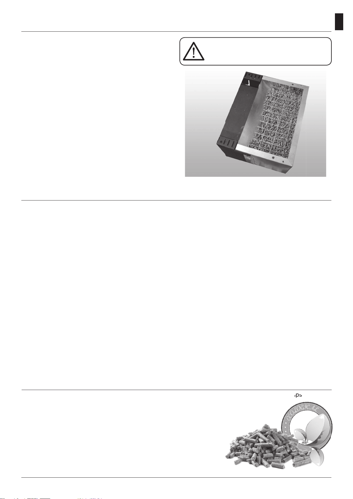
Kalor QUADRA 12D User manual

USER MANUAL
QUADRA 12D

Important information –new wood pellet stove
Thank you for choosing a new Kalor wood pellet stove from
your Authorised Kalor Dealer. We want you to get the full
benefits of your new Kalor stove, to enjoy its many
advantages and to always be safe. Please thoroughly read
this document as well as your stove’s manual and any other
documents/manuals provided to you.
User Manual
You have been provided with a User Manual for your stove.
You should read this and ensure that you understand how to
operate your new stove. The manual contains a lot of
information regarding the use and maintenance of your
stove as well as how to read and fix faults if they occur. If
there is anything you don’t understand, please ask your
supplier or installer for a full explanation.
Maintenance
Your stove should be regularly maintained –there are daily tasks. Regularity will depend on usage, please
read your manual to understand maintenance requirements for your model. Please also read our separate
sheet regarding the procedures for regular maintenance.
Ventilation
Vents have been installed for your safety and for optimal combustion and the correct operation of the stove.
It is essential that these vents are maintained and not blocked. For any low level vents, please ensure that
no obstructions are placed close the vent, either inside or outside.
Carbon Monoxide Alarms
Carbon Monoxide is a poisonous gas, created from combustion of many fuels, including wood pellets. A
carbon monoxide alarm has been installed and tested for your safety in accordance with Building
Regulations Part J. It is very important that you regularly test your carbon monoxide alarm and
replace batteries as necessary to ensure its correct operation.
Commissioning
All Kalor stoves & boilers MUST be commissioned for safety and to activate products warranty. Contact us
on 083 123 6445 or office@woodpelletstoves.ie to schedule your free commission today.

33
EN
Dear Customer,
We thank you for having chosen one of our products, the fruit of technological experience and of continual research for
a superior quality product in terms of safety, dependability, and service.
In this manual you will nd all the information and useful suggestions to use your product with the maximum safety
and efciency.
• Incorrect installation, incorrectly performed maintenance, improper use of the product release the manufacturer from
every eventual damage derived from the use of the stove.
• The unit cannot be used as an incinerator. Do not use fuels other than pellets.
• This manual has been realized by the manufacturer and constitutes an integral part of the product and must remain
with it during its entire lifetime. If the product is sold or transferred, be sure that the booklet is present since the
information contained in it are addressed to the buyer, and to all those persons of various titles who complete the
installation, use and maintenance.
• Carefully read the instructions and the technical information contained in this manual, before proceeding with the
installation, use, and any operation on the product.
• The observance of the indications contained in the present manual guarantees the safety of people and the product,
the economy of use and a longer functioning lifetime.
• Although the carefully studied design and the risk analysis done by our company has permitted the realization of a
safe product, in any case, before effecting any operation on the stove, it is recommended to keep said manual avail-
able and pay scrupulous attention to the instructions written therein.
• Be very careful when moving the ceramic details where present.
• Check the precise atness of the pavement where the product will be installed
• The wall where the product will be placed must not be constructed in wood, or in any case, made of an inammable
material, and in addition it is necessary to maintain a safety distance.
• While the stove is in operation, several parts of the stove (door, handle, sides) can reach high temperatures. Therefore
pay attention and use the proper precautions, above all in the presence of children, elderly or disabled persons, and
animals.
• Assembly must be performed by authorized persons (Authorized Assistance Center).
• Diagrams and drawings are furnished for the purpose of illustration; the manufacturer, with the intent of pursuing a
policy of constant development and renewal of the product can, without any notice, make any modications that are
believed opportune.
• When the stove is working at its maximum speed, it is strongly suggested to wear gloves while handling with the
door for pellets loading and the door handle.
• It is prohibited to install in bedrooms or in explosive environments.
• Only use replacement parts recommended by the supplier.
In the event of a re, disconnect the power supply, use an extinguisher and call the re ghters if necessary.
After that contact the Authorized Assistance Center.
Never cover the body of the stove in any way or obstruct the openings placed on the upper side
when the device is operating. All our stoves are trial lighted on the construction line.
This instruction booklet is an integral part of the product: make sure that it always accompanies the appliance, even in
case of transfer to another owner or in the case of transfer to another place. In the event of damage or loss, request a
copy from the area technician.
These symbols indicate specic messages in this booklet:
ATTENTION:
This warning sign indicates that the message to which it refers should be carefully read and under-
stood, because failure to comply with what these notices say can cause serious damage to the stove
and put the user’s safety at risk.
INFORMATION:
This symbol is used to highlight information which is important for proper stove operation. Failure to
comply with these provision will compromise use of the stove and its operation will not be satisfactory.
Quadra 12
Cod. 001109
We highly recommend to turn to our Authorized Service Centre for the installation and the rst
ignition of the device as it not only carries out the installation perfectly but also veries the re-
gular operation of it.

34
EN
Our company declares that the stove conforms to the
following norms for the EC European Directive labelling:
• 2014/30 UE (regulation EMCD) and following
amendments;
• 2014/35 UE (Low Voltage Directive) and following
amendments;
• 2011/65 EU (RoHS 2 directive);
• The New Rules of Construction Products (CPR-
Construction Products Regulation) No. 305/2011
regarding the construction world;
• For installations in Italy, please refer to UNI 10683/98 or
following changes. While installing the unit respect
the local, national and Europen rules;
• EN 55014-1; EN 55014-2; EN 61000-3-2; EN 61000-3-3;
EN 60335-1; EN 60335-2-102; EN 62233, EN 50581.
Safety information
Please carefully read this use and maintenance manual
before installing and operating the stove.
If clarication is needed, please contact the dealer or the
Authorized Assistance Center.
• The pellet stove must only be operated in living
environments. This stove, being controlled by an
electronic board, permits a completely automatic and
controlled combustion; the exchange, in fact, regulates
the lighting phase, 5 power levels and the shut down
stage, guaranteeing the safe operation of the stove.
• The basket used for combustion allows most of the ash
produced by the combustion of the pellets to fall into
the collection compartment. Nevertheless, check the
basket daily, given that not all pellets have high quality
standards (use only quality pellets recommended by the
manufacturer).
Responsibility
With the delivery of the present manual, we decline
all responsibility, both civil and penal, for accidents
deriving from the partial or total lack of observance
of the instructions contained herein. We decline every
responsibility derived from improper use of the stove,
from incorrect use by the user, from unauthorized
modications and/or repairs, from the use of replacement
parts that are not original for this model.
The manufacturer declines every civil or penal, direct or
indirect responsibility due to:
• Lack of maintenance;
• Failure to observe the instructions contained in the
manual;
• Use in non-conformity with the safety directives;
• Installation in non-conformity with the norms in force in
the country;
• Installation by unqualied or untrained personnel;
• Modications and repairs not authorized by the manu-
facturer;
• Use of non-original replacement parts;
• Exceptional events.
Norms and declarations of conformity
• Use only wood pellets;
• Keep / store the pellets in a cool dry
place;
• Never pour pellets directly on the hearth;
• The stove must be fueled only with quality pellets
with a diameter of 6 mm and a maximum length
of 30 mm, A1 certied according to the UNI EN
ISO 17225-2 standard, the type recommended
by the manufacturer.
• Before making the electrical connection of the
stove the discharge tubes must be connected
with the ue;
• The protective grill placed inside the pellet
container must never be removed;
• The environment where the stove is installed
must have a sufcient exchange of air;
• It is forbidden to operate the stove with the door
open or the glass broken;
• Do not use the stove as an incinerator; the stove
should be used only for the intended purpose;
• Any other use is considered improper and
therefore dangerous. Do not put in the hopper
other than wood pellets;
• When the stove is operating, the surfaces, glass,
handle and tubes become very hot: during
operation do not touch these parts without
adequate protection;
• Keep the fuel and other inammable materials
off the stove.

35
EN
Charge pellet
Fuel is loaded from the upper part of the stove by opening
a door. Pour the pellets in the hopper.
This is easier if performed in two steps:
• Pour half of the contents of the bag into the hopper and
wait for the fuel to settle on the bottom.
• Then pour in the second half;
• Keep the cover closed , after loading the pellets , the lid
of the fuel tank;
The stove is a product by heating, presents the external
surfaces particularly hot. For this reason, we recommend
extreme caution when operating in particular:
• Do not touch the stove body and the various components,
do not approach the door , it could cause burns;
• Do not touch the exhaust fumes;
• Do not perform any type of cleaning;
• Do not dump the ashes;
• Do not open the ash tray;
• Be careful that children do not come near;
Never remove the protection grille in the
hopper. When lling, do not let the sack
of pellets touch any hot surfaces.
• The device can be used by children that are not less than
8 years old and people with reduced physical, sensory or
mental capabilities, or lack of experience or knowledge,
provided being under supervision of someone responsible
or after having received instructions relating to the safe
use of the device and to the understanding of the dangers
inherent to it. Children should not play with the device.
Cleaning and maintenance to be performed by the user
should not be made by children without supervision;
• Do not use the stove as a ladder or scaffold;
• Do not put clothes to dry on the stove.
Any clothes hangers and suchlike must be kept a suitable
distance from the stove. - Risk of re
• Carefully explain that the stove is made from material
subjected to high temperatures for the elderly , the
disabled, and in particular for all children, keeping them
away from the stove during operation
• Do not touch the stove with wet hands: the stove has
electrical components that could produce sparks if
handled incorrectly.
• Never open the glass door of the pellet stove while the
stove is in operation.• The stove must be connected to an
electrical system equipped with an earthing conductor in
accordance with regulations 73/23 and 93/98 EEC;
• The system must be of adequate electrical power
declared the stove;
• Do not wash the inside of the stove with water.
The water could damage the electrical insulation, causing
electric shock;
• Do not expose your body to hot air for a long time. Do
not overheat the room you are in and where the stove is
installed.
This can damage the physical conditions and cause
health problems;
• Do not expose to direct the ow of hot air plants or
animals;
• The pellet stove is not a cooking element;
• External surfaces during operation can become very
hot. Do not touch them except with the appropriate
protection.
• The plug of the device power cable must be connected
only after installation and assembly of the device and
must remain accessible after installation, if the unit is not
provided of a double-pole switch suitable and accessible.
• Do not lay objects, glasses, infusers, room perfumers
on the stove, they could be damaged or to damage the
stove (in this case de warranty does not respond).
Instructions for safe and efficient use
The pellets are cylinders of compressed wood, produced from sawdust and wood processing (chips and
sawdust), generally produced by sawmills and carpenters. The binding capacity of the lignin contained
in wood, allows to obtain a compact product without adding additives and foreign chemicals to the
wood, is therefore obtained a natural fuel with high yield.
The use of expired pellets or any other unsuitable material can damage parts of the
thermostove and impair proper operation: this can lead to the termination of the
guarantee, and its producer responsibility.
For our products use pellets diameter 6 mm, length 30 mm and a
maximum of 6% and A1 certied according to the UNI EN ISO 17225-2
standard. Keep the pellets away from heat sources and not in humid
environments or with explosive atmosphere.
Pellet
The pellets are cylinders of compressed wood, produced from sawdust and wood processing (chips

36
EN
Remote Control
The remote control (Fig. 3) used to adjust water temperature
power and the on/off functions for the pellet stove.
To start the stove, press key and the stove will
automatically enter the starting phase.
Press keys +(1) and -(2) to adjust temperature, and
use keys +(6) and -(5) to adjust operating power.
To turn off the stove, hold down key .
To replace the 3 volt battery located on the back of the
remote control, pull the centre of the cover and the lever
on the side of the same, replace the battery observing the
correct polarity (Fig. 4)
Fig. 3 Fig. 4
Fig. 3
Technical Specification
1000
1068
249,5
1100
367,50
425
7098,4
949
Y
253
844,5
191,75195
768,25
424
X
Ø 50
Ø 80
Ø 80
18,5°
18,5°
18,5°
18,5°
DETTAGLIO X
SCALA 2 : 15
Regolazione aria
51
DETTAGLIO Y
SCALA 1 : 2
Staa ssaggio muro
D
E
F
C
1
2
3
4
B
A
3
2
1
5
C
D
4
6
7
8
A
B
Descrizione
Materiale
Trattamento
Codice
Sostituisce
Questo disegno è di proprietà della ditta T-DESIGN e non può essere ceduto a terzi senza nostro preventivo consenso
Modiche
Data emiss.
Formato
Scala
Quote senza indicazione di tolleranza :
UNI EN 22768/1 m; UNI EN 22768/2 K
LUNGHEZZE
...6
>6
...30
>30
...120
>120
...400
>400
...1000
+
0.1
++
0.3
0.2
+
0.5
+
0.8
FILETTATURE
METRICHE ISO
ANGOLI
+
1°
0.1
+
FORI
Maschio
Femmina
6g
7H
1:15
A3
MG001000
26/10/2012
design
www.t-design.it
progettazione
meccanica
e design
Peso
g
Assieme stufa da corridoio Kalor
126357.41
N.B.
1 - Measures with a tolerance of about 10 mm
2 - Measures and images are indicative
and can vary depending on the aesthetic
of the pellet stove.

37
EN
37
I
'
(
)
&
%
$
&
'
$
%
'HVFUL]LRQH
0DWHULDOH
7UDWWDPHQWR
&RGLFH
6RVWLWXLVFH
0RGLILFKH
'DWDHPLVV
)RUPDWR
6FDOD
4XRWHVHQ]DLQGLFD]LRQHGLWROOHUDQ]D
81,(1P81,(1.
/81*+(==(
!
!
!
!
),/(77$785(
0(75,&+(,62
$1*2/,
)25,
0DVFKLR
)HPPLQD
J
+
$
0*
ZZZWGHVLJQLW
SURJHWWD]LRQH
PHFFDQLFD
HGHVLJQ
3HVR
J
6WXIDGDFRUULGRLRHVWHWLFD6/,0
'
(
)
&
%
$
&
'
$
%
'HVFUL]LRQH
0DWHULDOH
7UDWWDPHQWR
&RGLFH
6RVWLWXLVFH
0RGLILFKH
'DWDHPLVV
)RUPDWR
6FDOD
4XRWHVHQ]DLQGLFD]LRQHGLWROOHUDQ]D
81,(1P81,(1.
/81*+(==(
!
!
!
!
),/(77$785(
0(75,&+(,62
$1*2/,
)25,
0DVFKLR
)HPPLQD
J
+
$
0*
ZZZWGHVLJQLW
SURJHWWD]LRQH
PHFFDQLFD
HGHVLJQ
3HVR
J
6WXIDGDFRUULGRLRHVWHWLFD6/,0
In order to achieve the test report results, please load the performance parameters retained
by the manufacturer and the qualied technician. They will use these parameters once veried
that, during the installation, it is possibile to reproduce the laboratory conditions.

38
EN
PARAMETER M. UNITS QUADRA 12C
Heat input kW 12,01
Nominal heat output kW 11,14
Reduced heat output kW 2,92
CO concentration at nominal refer-
ence (13% O
2
)
mg/m375,7
CO concentration at reduced refer-
ence (13% O2)
mg/m3137,1
Nominal efciency % 92,74
Reduced efciency % 95,93
Pellet consumption (min-max) Kg/h 0,62 - 2,448
Heated surface mc 270
Flue gas ow rate (min-max) g/s 10,6
Draft (min-max) Pa 10 - 12
Flue gas temperature (min-max) °C 55,2 - 132,5
Tank capacity Kg 19
Recommended Pellet (Ø x H) mm 6 x 30
Smoke outlet tube mm 80
Diameter air intake mm 50
Nominal voltage V 230
Nominal frequency Hz 50
Power consumption max W 300
Stove weight Kg 120
Ambiental decree n.186
Energetic class A+
“Aria Pulita” Certication code H20-P-006
IEE 125
N° Test Report K19412016Z1
It is recommended that the control of emissions after installation.

39
EN
30 cm
(B)
Min.
100
cm2
10 cm (A)
30 cm
Min.
100
cm
10 cm (A)
Operating area
For proper functioning and a good temperature
distribution, the stove shoul be positioned in a location
where it is able to take in the air necessary for combustion
of the pellet (about 40 m3/h must be available), as laid
down in the standard governing the installation and in
accordance with local national standards. The volume of
the room must not be less than 30 m3.
The air must come in through permanent openings made
in walls (in proximity to the stove) which give onto the
outside, with a minimum cross-section area of 100 cm2.
These openings must be made in such a way that it is not
possible for then to be obstructed in any way.
Alternatively, the air can be taken from rooms adjacent
to the one which needs ventilating, as long as they are
provided with an air intake from the outside, and are not
used as bedrooms or bathrooms, and provided there
is no re risk such as there is for example in garages,
woodsheds, and storerooms, with particular reference to
what is laid down in current standards.
It is not permissible to install the stove in
bedrooms, bathrooms, or in a room where
another heating appliance is installed
(replace, stove etc.) which does not have its own
independent air intake.
Locating the stove in a room with an explosive
atmosphere is prohibited.
The oor of the room where the stove is to be
installed must be strong enough to take its weight. If
walls are ammable, maintain a minimum distance
of 10 cm at the rear (A), of 30 cm at the side (B) and
100 cm at the front.
If the room contains objects which are believed to
be particularly delicate, such as drapes, sofas and
other furniture, their distance from the stove should
be considerably increased. The two side walls of
the stove must be accessible for maintenance by
authorized technicians.
Connection to the external air intake
It is essential that at least as much air must be able to ow
into the room where the stove is installed as is required for
proper combustion in the appliance and for the ventilation
of the room.
This can be effected by means of permanent openings in
the walls of the room to be ventilated, which give onto the
outside, or by single or collective ventilation ducts.
For this purpose, on the external wall near the stove, a
hole must be made with a minimum free cross-section of
100 cm2. (equivalent to a round hole of 12 cm diameter or
a square hole 10x10 cm) protected by a grille on the inside
and the outside.
The air intake must also:
• communicate directly with the room where the stove
is installed
• be protected by a grille, metal mesh or suitable guard,
as long as this does not reduce the area below the
minimum
• be positioned in such a way as to be impossible to
obstruct
It is not compulsory to connect the air
intake directly with the stove (so that it
draws air directly from outside), but it is
essential at all events to ensure an airow of 40
cubic metres per hour by the use of a hole of the
dimensions given. See standard UNI 10683.
In the presence of wood oors, install a
oor protection surface in compliance
with the rules in force in the country

40
EN
Connection to the ue pipe
The ue pipe must have internal dimensions not larger
than 20x20 cm, or diameter 20 cm. In the event of larger
dimensions, or of the ue pipe being in poor condition ( for
example cracks, poor insulation, etc.), it is advisable to t
a stainless steel pipe of suitable diameter inside the ue
pipe throughout its length, right up to the top.
Check with suitable instruments that there is a draught
between 10 Pa and 12 Pa. This type of connection
ensures the evacuation of the fumes even in the event of
a temporary power cut. At the bottom of the ue pipe,
provide an inspection cap to allow periodic checking and
cleaning, which must be done annually. Make a gas-tight
connection to the ue pipe, using pipes and connectors
as recommended by us. You must ensure that a windproof
cowl should be tted which complies with the standards
in force
Connection to an external ue with insulated or
double-wall pipe
The only type of pipe which is permissible is insulated
(double-walled) stainless steel, smooth on the inside,
xed to the wall. Flexible stainless steel pipe must not be
used. At the bottom of the ue pipe, provide an inspection
cap to allow periodic checking and cleaning, which must
be done annually. Make a gas-tight connection to the ue
pipe, using pipes and connectors as recommended by us.
You must ensure that a windproof cowl should be tted
which complies with the standards in force.
Check with suitable instruments that there is a draught
between 10 Pa and 12 Pa.
Connection to the ue pipe
For proper functioning, the connecting pipe between the
stove and the chimney or ue duct must have a slope of
not less than 3% in the horizontal stretches, the length of
which must not exceed 2 metres and the vertical distance
between one tee connector and another (change of
direction) must not be less than 1,5 m. Check with suitable
instruments that there is a draught between 10 Pa and 12
Pa. At the botton of the ue pipe, provide an inspection
cap to allow periodic checking and cleaning, which must
be done annually. Make a gas-tight connection to the ue
pipe, using pipes and connectors as recommended by us.
You must ensure that a windproof cowl should be tted
which complies with the standards in force.
Fireplace ue gas
Avoid contact with combustible materials (example:
wooden beams) and in any case provide for their insulation
with ame retardant material. In case of pipe penetrations
through roofs or walls is recommended to use special
kits crossing, certicates, are available commercially. In
the event of a chimney re, turn off the stove, disconnect
from the network and never open the door. Then call the
authorities.
Fig. 3: connection to an
external ue with insulated
or double-wall pipe.
Fig. 2: connection to the
ue pipe.

41
EN
Smoke discharge
The discharge system must be for the stove only (it
is not permissible to discharge into ues in common
with other devices). The smoke discharge takes place
through the 8 cm. A “T” with a condensation collection
cap should be provided. The smoke discharge of
the stove must be connected with the outside using
a steel or black tube (resistant up to 450°C) without
obstructions.
The tube must be hermetically sealed. To make the
tubes airtight and for their eventual insulation, it is
necessary to use material resistant up to at least 300°C
(silicone or putty for high temperatures).
The horizontal sections can be up to 2 m long. It is
possible to have up to three 90° curves. If the discharge
tube does not insert in the ue, an opportunely
fastened vertical section of at least 1.5 m is necessary
(except for evident safety contraindications) and a
windproof termination (Fig.3). The vertical duct can be
inside or outside. If the smoke duct is outside it must
be insulated (Fig.4). If the smoke duct is inserted in a
ue, this must be certied for solid combustibles and
if it is larger than 150 mm in diameter, modication is
necessary by inserting a tube and sealing the discharge
with respect to the parts in brickwork.
It must be possible to inspect all the sections of the
smoke duct. If it is a xed duct it must have openings
for inspection and cleaning.
External air intake
The stove must be furnished with the air necessary to
guarantee the regular functioning of the combustion
and an environmental well being.
• Be sure that the room where the stove is installed has
sufcient aeration and, if necessary, install an air intake
duct with a minimum recommended diameter of 50 mm
to bring in air from the outside.
• The external air intake must communicate with the
stove and positioned so that it is not obstructed. It
must be protected with a permanent non-closable grill
or other suitable protection provided that the minimum
diameter is not reduced.
• The air ow can also be acquired from a locale adjacent
to where the stove is installed as long as that ow can
freely cross the permanent non-closable openings that
communicate with the outside.
• The presence in the local adjacent to where the stove
is installed, of other devices in use or of suction devices
that cause a contrary draught effect must not create
a lower air pressure in the locale than in the outside
environment.
• In the adjacent locale the permanent openings must
respond to the requisites which are listed in the points
above.
A. Smoke discharge
A
A
A
B
B
A. Horizontal air duct
B.Vertical air duct
A. Horizontal air duct
B. Discharge of smoke
According to the norm UNI
10683/98, the stove must not be
in the same environment where
extractors, type B gas devices or
in any case, devices that create lower
atmospheric pressure in the locale are
found.

42
EN
The chimney cap
The chimney cap must respect the following requirements:
• It must have the equivalent diameter and internal form
of the ue.
• It must have a useful outlet diameter of not less than
double that of the ue.
• The chimney cap on the roof or that remains in contact
with the outside (for example, in case of open lofts or
attics), must be covered with elements in brick or tile
and must, in any case, be well insulated.
• It must be constructed to prevent rain, snow, and
extraneous bodies from entering the ue and so that
the discharge of the products of combustion is not
inhibited by wind from any quarter or strength (wind-
proof chimney cap).
• The chimney cap must be positioned in such a way as
to guarantee the adequate dispersion and dilution of the
products of combustion and in any case, must be out of
the reux zone. This zone has different dimensions and
forms according to the angle of inclination of the roof so
it is necessary to adopt minimum heights.
• The chimney cap must be a wind-proof type and must
be above the ridge.
• Eventual structures or other obstacles that are higher
than the chimney cap must not be too close to the
chimney cap itself.
• The device should not be installed in the ue shared.
REMARKS:
- the appliance must be installed by a qualied technician in
possession of the technical and professional requirements
according to the DM37/2008 that, under its responsibility,
to ensure compliance with the rules of good technique.
- you need to keep in mind all laws and national, regional,
provincial and municipal laws of the country in which you
installed the device
- check that the oor is not ammable: if necessary use a
suitable platform
- in the room where the generator must be installed to
heat must not pre-exist or be installed with an extractor
hood or ventilation ducts of the collective type.
Should these devices be located in adjacent rooms
communicating with the installation, and ‘prohibited the
simultaneous use of the heat generator, where there is a
risk that one of the two rooms being placed in depression
than the other
- it is not permissible to install in bedrooms or bathrooms.
Distance to objects
It is also recommended to keep the pellets and all
ammable materials at a suitable distance from the stove.
20 cm
100 cm
5 cm
Minimum aeration for comburant air intake
The combustion air must be taken from the outdoor
ambience absolutely.
For a correct and safe placement of the air intake all the
measures and prescriptions must be respected. There are
distances to respect to prevent the comburant air from
being subtracted from another source: for example the
opening of a window could cause eddies in the outside air
subtracting it from the stove.
Installation of wall plug and xing the bracket onto
the wall
To ensure the installation at the right distance from the
wall, it has been inserted, in series, an aluminium guide,
having an end key and the other an end ring. The end key
is inserted into the special slot provided on the heater rear.
The end ring is instead xed to the wall. In this way, the
heater will be perfectly xed to the closest surface to
ensure a perfect stability and the right anchoring at the
safety distance.
For safety reasons, it is mandatory to
anchor the heater with the special guide
directly to the supporting wall.
YES NO
Caratteristiche del comignolo

43
EN
Air distribution frontal-canalization
Canalization
The display for the programming of the heater is mounted
on the stoves side.
Under the door are positioned:
• a knob for cleaning the tube bundle;
• a handgrip for the manual adjustment of air.
The numbering allows distribution of air only frontally or
towards the vertical or horizontal ducting.
to the bottom side: fastening the at cable to the board
Sliding top cover (where present)
Fan
acc
1
It is possible to manually adjust the distribution of air
between frontal and ducted. To adjust the outgoing air, it
will be necessary to open the upper door and move the
lever inside of the stove from right to left. The more the
lever is moved to the right, the more the air is directed to
the front of the stove. The manual setting will act on the
gate valve of air distribution.

44
EN
Stove ignition
Remove any components which might burn from the rebox and from the glass
(various instructions and adhesive labels)
Charge pellet
Fuel is loaded from the upper part of the Stove by opening a door. Pour the pellets in the hopper. When empty, this is
easier if performed in two steps:
• Pour half of the contents of the bag into the hopper and wait for the fuel to settle on the bottom.
• Then pour in the rest.
Never remove the protection grille in the hopper. When lling, do not let the sack
of pellets touch any hot surfaces.
The brazier should be cleaned before each starting.
Control Panel (Fig. 2)
Button is used to switch on and / or off the Stove and to exit programming.
Buttons
is used to switch on and / or off the Stove and to exit programming.
and
is used to switch on and / or off the Stove and to exit programming.
are used to adjust temperature, for displays and for the programming functions.
Buttons and
are used to adjust temperature, for displays and for the programming functions.
are used to adjust heating power.
Button e is used to adjust temperature and programming functions.
The upper and lower displays are used to view different messages.
LED SYMBOL DESCRIPTION
1The LED is on when the parameter UT01 on the menu is not on OFF and the weekly or daily
programming are set.
2The LED starts up every time the Stove is loading pellets
3The LED blinks when the board signalises a change in temperature or power set by the infrared
remote control.
4The LED is on when the room temperature reaches the value set on the menu SET Water.
5 SET The LED blinks to indicate that you are entering the menu user/technician or that you are modifying
the temperature set.
6The LED switches on when the water circulator is working.
Fan
acc
1
It is advisable to use dry wood pellets, up to 6 mm in diameter.

45
EN
Preliminary checks
Before switching on the pellet Stove, make sure that the pellet hopper is full, the combustion chamber is clean, the glass
door is closed, the power supply plug is connected and the switch on the back is set to “1.”
TURNED OFF
The Stove is off.
TURNED ON
The Stove is in the rst ignition phase.
The glow plug and fume extractor are active.
LOAD PELLET
In this phase of the ignition process the Stove starts loading the pellets into the brazier.
The glow plug, the fume extractor and the cochlea engine are active.
FIRE PRESENT
In this phase of the ignition process the Stove starts loading the pellets into the brazier.
The fume extractor and the cochlea engine are active.
BRAZIER CLEANING
The Stove is cleaning the basket.
The smoke extractor runs at maximum speed and the pellet load is at minimum.
WORK
The Stove is working, in this case at power 3.
The detected room temperature is 21 ° C. During normal work, the fumes fan, the auger motor
and the room fan are active.
21 :10
22°C P-1
TURNED OFF
14 :35
22°C P-1
FIRE
present
14 :35
21°C P-2
ACCENDE
14 :35
21°C P-2
LOAD
pellet
15 :18
22°C P-3
WORK
15 :18
22°C p-2
BRAZIER
CLEANING
Information on the display

46
EN
Alarm signals
In the event of a working defect, the system informs the user about the type of failure occurred.
The following table summarises the alarms, kind of problem and possible solution:
Regular checks should be carried out by the user, who should only contact the Authorized
Assistance Center if no solution is found.
Display Kind of problem Solution
ALAR 1 BLACK OUT There is no power supply
As soon as the power supply is back, the Stove starts a coo-
ling cycle. After completing the cycle it starts working auto-
matically
ALAR 2 PROBE
EXHAUST
The smokes sensor is broken or not con-
nected to the pcb Contact an Authorized Assistance Center
ALAR 3 HOT
EXHAUST Smokes temperature too high
Switch off the Stove, allow it to cool down and perform ordi-
nary cleaning. If the problem persists, contact an Authorized
Assistance Center for cleaning the Stove and the ue
ALAR 4 FAN
FAILURE Smokes extractor blocked or broken Contact an Authorized Assistance Center
ALAR 5 NO
LIGHTIN
The Stove cannot start up
This is the rst light-up
Fill in the tank with pellets
Start up again
ALAR 6 NO
PELLET
The pellet Stove switched off while
working Fill in the tank with pellets
ALAR 7 SAFETY
THERMAL
The water temperature exceeds 90°C.
The circulating pump is blocked or there
is no water in the hydraulic system
Check the power supply on the pump.
Check limestone does not block the pump impeller
ALAR 8 FAILURE
DEPRESS Obstructed ue Clean the ue or check there are no obstructed grids near the
smokes exhaust
ALAR B
ERROR
TRIAC
COCLEA
The cochlea loads too much pellet Contact an Authorized Assistance Center
ALAR C PROBE
WATER Water probe faulty Contact an Authorized Assistance Center
ALAR D HOT
WATER Water temperature too high
Allow the Stove to cool down. If the problem persists, con-
tact an Authorized Assistance Center and have the hydraulic
system checked
ALAR E PRESS
WATER Water pressure too high
Allow the Stove to cool down. If the problem persists, con-
tact an Authorized Assistance Center and have the hydraulic
system checked
SERV The Stove has worked for 1300 hours.
Supplementary maintenance required Contact an Authorized Assistance Center

47
EN
Programming menu
Menu 02 SET CLOCK
To access the set clock option, press the “SET” button (3), with the button - (5) scroll through the submenus until MENU
02 - SET CLOCK and with buttons 1 and 2 select the current day. Press the “SET” button (3) to conrm.
Then use buttons 1 and 2 to set the time and press “SET” (3) to advance to the minutes setting by pressing buttons 1 and
2. By pressing set again it’s possible to access various submenus in order to set the date, day, month, and year. To do so,
repeat the steps indicated above, using buttons 1, 2, and 3.
The following table briey describes the structure of the menu, focusing only on those selections which are available to
the user.
Set the current time and date. The device comes equipped
with a lithium battery that allows the internal clock to
operate autonomously for over 3-5 years.
Menu 03 SET CHRONO
Press the “SET” button (3) and then button 5 to arrive at the desired menu; press “SET” (3) to enter.
Enter menu M-3-1 and with buttons 1 and 2 select whether or not to activate the thermostat (on/off), which allows you
to program the automatic ignition of the Stove.
Once the thermostat is activated/deactivated, press button “4” (OFF) and continue scrolling though the submenus using
button 5. Select which submenu you wish to enter in order to access the daily, weekly, and weekend programmes.
To set the ignition times and days repeat the previous steps:
- access the submenu using “SET” (3)
- adjust the days, times, and activation status (on/off) with buttons 1 and 2
- conrm by pressing the “SET” button (3)
- exit from the submenu/menu with button 4 to turn it off
The following table briey describes the structure of the menu, focusing only on those selections which are available to
the user.
level 1 level 2 level 3 level 4 value
03 - set crono
01 - abilita crono
01 - abilita crono on/off
02 -
program. giorno
01 - crono giorno on/off
02 - start 1 giorno ora
03 - stop 1 giorno ora
04 - start 2 giorno ora
05 - stop 2 giorno ora
06
Menu 02
menu
clock
menu levelinput
dialogue
level 1 level 2 level 3 level 4 value
02 - set clock
01 - day day of the week
02 - hour hour
03 - minutes minutes
04 - day day of the month
05 - month month
06 - year year

48
EN
level 1 level 2 level 3 level 4 value
03 - set thermostat
01 -
activate thermos.
01 -
activate thermos.
on/off
02 -
day programme
01 -
daily thermostat
on/off
02 - start 1 day hour
03 - stop 1 day hour
04 - start 2 day hour
05 - stop 2 day hour
03 - week program.
01 - week thermostat on/off
02 - start program. 1 hour
03 - stop program. 1 hour
04 - monday progr. 1 on/off
05 - tuesday progr. 1 on/off
06 -
wednesday prog. 1
on/off
07 - thursday prog 1 on/off
08 - friday prog 1 on/off
09 - saturday prog 1 on/off
10 - sunday prog 1 on/off
11 - start program. 2 hour
12 - stop program. 2 hour
13 - monday progr. 2 on/off
14 - tuesday progr. 2 on/off
15 -
wednesday prog. 2
on/off
16 - thursday prog 2 on/off
17 - friday prog 2 on/off
18 - saturday prog 2 on/off
19 - sunday prog 2 on/off
20 - start program. 3 hour
21 - stop program. 3 hour
22 - monday progr. 3 on/off
23 - tuesday progr. 3 on/off
24 -
wednesday prog. 3
on/off
25 - thursday prog 3 on/off
26 - friday prog 3 on/off
27 - saturday prog 3 on/off
28 - sunday prog 3 on/off
29 - start program. 4 hour
30 - stop program. 4 hour
31 - monday progr. 4 on/off
32 - tuesday progr. 4 on/off
33 -
wednesday prog. 4
on/off
34 - thursday prog. 4 on/off

49
EN
selezione signicato valori possibili
START 1 ora di attivazione ora - OFF
STOP 1 ora di disattivazione ora - OFF
START 2 ora di attivazione ora - OFF
STOP 2 ora di disattivazione ora - OFF
Menu 03 SET CHRONO
Submenu 03 - 01 - activate thermostat
This allows you to activate and deactivate all of the functions
of the thermostat
Submenu 03 - 02 - daily programme
This allows you to enable,disable, and set the daily functions
of the thermostat.
Submenu 03 - 03 - weekly programme
This allows you to enable, disable, and set the weekly
functions of the thermostat.
It’s possible to set two operating ranges delimited by the
times set according to the following table where the OFF
setting tells the clock to ignore the command:
The weekly programmer has 4 independent programmes whose nal effect is composed of the combination of the 4
individual programmes. The weekly programmer can be activated or deactivated. Additionally, by setting OFF in the time
eld, the clock ignores the corresponding command.
Planprogramming carefully inorder toavoidoverlapping activation/deactivation
times in a single day in different programmes.
oFF
M-3-1-01
enable
thermos
menu level
input
dialogue
08 : 15
M-3-2-02
START 1
day
menu levelinput
dialogue
05 : 40
M-3-3-02
START
prog‐1
menu levelinput
dialogue
35 - friday prog. 4 on/off
36 - saturday prog. 4 on/off
37 - sunday prog. 4 on/off
04 -
week-end program.
01 - therm. week-end
02 - start 1
03 - stop 1
04 - start 2
05 - stop 2

50
EN
Submenu 03 - 04 - program week-end
This allows you to enable, disable, and set the weekend
functions of the thermostat (days 5 and 6, or Saturday and
Sunday).
REMARKS:
- in order to avoid confusion and unwanted start-ups or shutdowns, activate only one programme at a time unless you
know exactly what you’d like to achieve
- deactivate the daily program if you want to use the weekly program
- always leave the weekend programme deactivated if you use weekly programmes 1, 2, 3, and 4.
- activate the weekend programme only after you have deactivated the weekly programme.
Menu 04 - select language
Press the SET button to access the menu and press (5) up to the MENU 04 - SELECT LANGUAGE.
Then press the SET button to access the menu. Select the desired language using the keys
(5) up to the MENU 04 - SELECT LANGUAGE.
(1) e
(5) up to the MENU 04 - SELECT LANGUAGE.
(2)
08 : 30
M-3-4-03
STop 1
week‐end
menu levelinput
dialogue
PROGRAMME 1
menu level selection meaning
possible values
02-03-02 START PROGRAM 1 activation time time - OFF
02-03-03 STOP PROGRAM 1 shut-off time time - OFF
02-03-04 MONDAY PROGRAM 1
reference day
on/off
02-03-05 TUESDAY PROG 1 on/off
02-03-06 WEDNESDAY PROG 1 on/off
02-03-07 THURSDAY PROGR 1 on/off
02-03-08 FRIDAY PROGRAM 1 on/off
02-03-09 SATURDAY PROGR 1 on/off
02-03-10 SUNDAY PROGR 1 on/off
PROGRAMME 2
menu level selection meaning
possible values
03-03-11 START PROGRAM 2 activation time time - OFF
03-03-12 STOP PROGRAM 2 shut-off time time - OFF
03-03-13 MONDAY PROGRAM 2
reference day
on/off
03-03-14 TUESDAY PROG 2 on/off
03-03-15 WEDNESDAY PROG 2 on/off
03-03-16 THURSDAY PROGR 2 on/off
03-03-17 FRIDAY PROGRAM 2 on/off
03-03-18 SATURDAY PROGR 2 on/off
03-03-19 SUNDAY PROGR 2 on/off
PROGRAMME 3
menu level selection meaning
possible values
03-03-20 START PROGRAM 3 activation time time - OFF
03-03-21 STOP PROGRAM 3 shut-off time time - OFF
03-03-22 MONDAY PROGRAM 3
reference day
on/off
03-03-23 TUESDAY PROG 3 on/off
03-03-24 WEDNESDAY PROG 3 on/off
03-03-25 THURSDAY PROGR 3 on/off
03-03-26 FRIDAY PROGRAM 3 on/off
03-03-27 SATURDAY PROGR 3 on/off
03-03-28 SUNDAY PROGR 3 on/off
PROGRAMME 4
menu level selection meaning
possible values
03-03-29 START PROGRAM 4 activation time time - OFF
03-03-30 STOP PROGRAM 4 shut-off time time - OFF
03-03-31 MONDAY PROGRAM 4
reference day
on/off
03-03-32 TUESDAY PROG 4 on/off
03-03-33 WEDNESDAY PROG 4 on/off
03-03-34 THURSDAY PROGR 4 on/off
03-03-35 FRIDAY PROGRAM 4 on/off
03-03-36 SATURDAY PROGR 4 on/off
03-03-37 SUNDAY PROGR 4 on/off
Table of contents
Popular Pellet Stove manuals by other brands

Avalon
Avalon Avanti PS owner's manual

Quadra-Fire
Quadra-Fire MTV-E2-CSB installation manual

Victoria
Victoria Vittoria B instruction manual

Enviro
Enviro Omega Specifications

Red Heating
Red Heating LOTO Multiair installation guide

Hudson River Stove Works
Hudson River Stove Works DAVENPORT Owners manual/install guide

Vogelzang International
Vogelzang International VG5790 owner's manual

Harman
Harman P43 Installation & operating manual

Enviro
Enviro EF2 Service manual

Heatilator
Heatilator ECO CHOICE ECO-ADV-PS35 installation manual

Drolet
Drolet ECO-55 Operation manual

Travis Industries
Travis Industries Lopi 400 PS Installation, operation and maintanance manual