4 7058-205K August 21, 2018
HEATILATOR ECO-CHOICE
E. Mobile Home Approved
• This appliance is approved for mobile home
installations when not installed in a sleeping room and
when an outside combustion air inlet is provided.
• The structural integrity of the mobile home oor, ceiling,
and walls must be maintained.
• The appliance must be properly grounded to the frame
of the mobile home with #8 copper ground wire, and
use only listed double-wall connector pipe.
• Outside Air Kit, part 811-0872 or OAK-3 must be
installed in a mobile home installation.
• Appliance must be secured to mobile home structure.
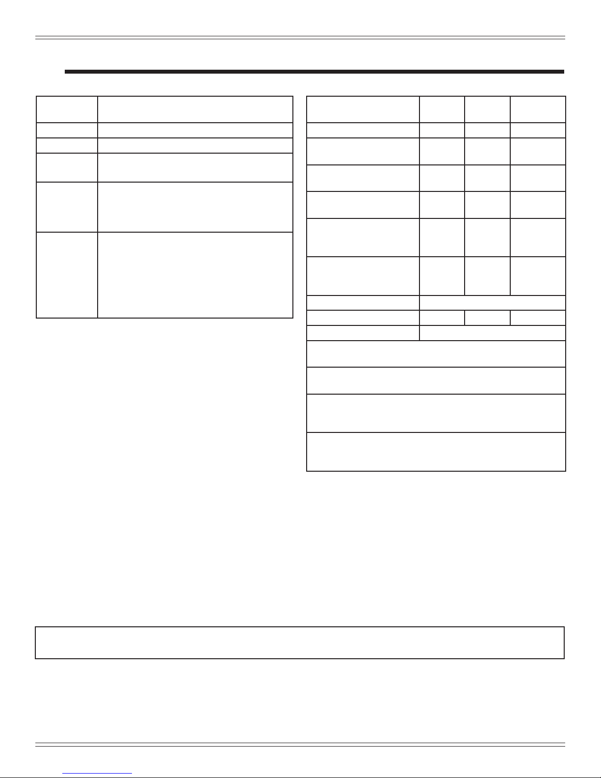
C. Glass Specications
This appliance is equipped with 5mm ceramic glass.
Replace glass only with 5mm ceramic glass. Please
contact your dealer for replacement glass.
D. Electrical Rating (on high)
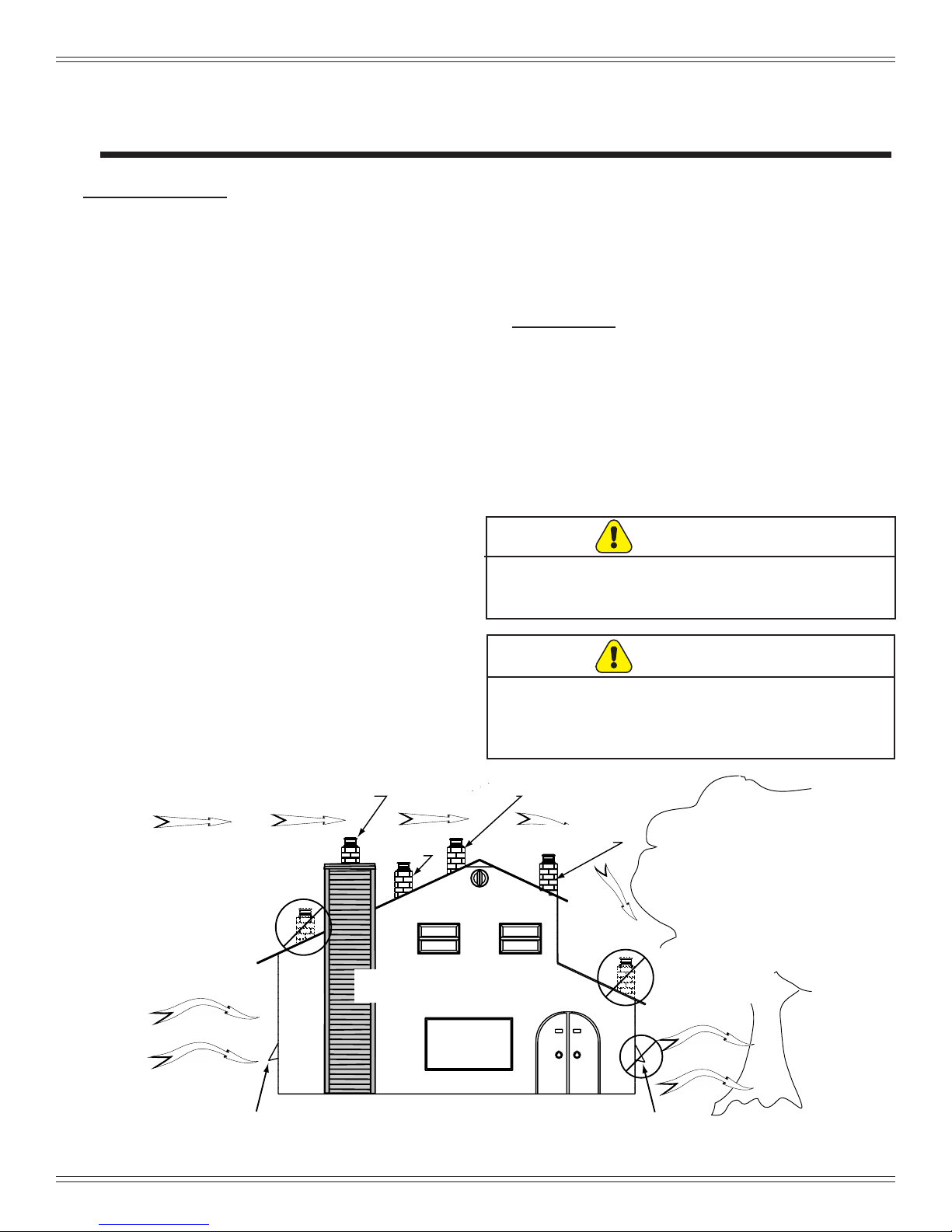
H. Sleeping Room
When installed in a sleeping room it is recommended that
3ft of vertical be installed prior to horizontally exiting the
room and a smoke/CO alarm be installed in the bedroom.
The size of the room must be at least 50ft³ per 1,000 Btu/hr
stove input, if the stove exceeds the room size, out air must
be installed.
I. Stove Composition
These pellet burning stoves are made of steel, cast iron or
a combination of both with a ceramic viewing glass. These
stoves incorporate a self-feeding system including a fuel
storage hopper and a mechanical feed system which is
controlled by a micro-processing control board. Each model
contains a variable speed distribution blower to circulate
room air through the heat exchanger and out to the room
and a combustion blower which forces the exhaust out of
the stove.
Model PS35: 115 VAC, 60 Hz, Start 3.8 Amps, Run
1.3 Amps
Model PS50: 115 VAC, 60 Hz, Start 5.1 Amps, Run
3.0 Amps
Model CAB50: 115 VAC, 60 Hz, Start 5.1 Amps, Run
3.0 Amps
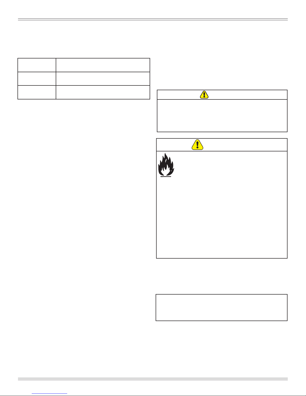
G. Combustible Materials
F. Non-Combustible Materials
Material which will not ignite and burn, composed of any
combination of the following:
- Steel
- Plaster
- Brick
- Iron
- Concrete
- Tile
- Glass
- Slate
Materials reported as passing ASTM E 136, Standard Test
Method for Behavior of Metals, in a Vertical Tube Furnace
of 750° C.
Material made of/or surfaced with any of the following
materials:
- Wood
- Compressed Paper
- Plant Fibers
- Plastic
- Plywood/OSB
- Sheet Rock (drywall)
Any material that can ignite and burn: ame proofed or not,
plastered or non-plastered.
J. California - Prop65
WARNING
This product and the fuels used to operate this product (wood), and
the products of combustion of such fuels, can expose you to
chemicals including carbon black, which is known to the State of
California to cause cancer, and carbon monoxide, which is known to
the State of California to cause birth defects or other reproductive
harm. For more information go to: WWW.P65Warnings.ca.gov
NOTE: Hearth & Home Technologies, manufacturer
of this appliance, reserves the right to alter its
products, their specications and/or price without
notice.
Improper installation, adjustment, alteration, service or
maintenance can cause injury or property damage.
For assistance or additional information, consult a qualied
installer, service agency or your dealer.
• Installation and use of any damaged appliance.
• Modication of the appliance.
• Installation other than as instructed by Hearth &
Home Technologies.
• Installation and/or use of any component part not
approved by Hearth & Home Technologies.
• Operating appliance without fully assembling all
components.
• Operating appliance without legs attached (if
supplied with appliance).
• Do NOT Over re - If appliance or chimney connector
glows, you are over ring.
Any such action that may cause a re hazard.
WARNING
Fire Risk
Hearth & Home Technologies disclaims any
responsibility for, and the warranty will be voided
by, the following actions: