Kaman SERIES 8000 User manual

Reference Manual
SERIES 8000
ENCLOSURES
Copyright © 2000 Kaman Aerospace Corporation
PART NO: 860093-001 Measuring & Memory Systems
Last Revised: 3/16/01 217 Smith Street
Middletown, CT 06457
www.kamansensors.com or 860-632-4442


Series 8000 Enclosures
Reference Manual
1/2 Rack Instrumentation Case (3U/42HP)
3/4 Rack Instrumentation Case (3U/63HP)
Full 19" Subrack (3U/84HP)
Kaman Measuring Systems
P/N 860093-001, Revised 3/16/01

4
Series 8000 Systems
The Series 8000 is a modular packaging system for Kaman Instrumentations line of inductive
displacement transducer electronics. The Series 8000 enclosures integrate various measuring
channels, function cards, power supplies, and displays into a coherent application specific
industrial package. Sensors for the measuring channels are available that measure
displacements in the microinch/nanometer ranges as well as sensors that can make accurate
displacement measurements at up to 1000oF. Function cards are available that can take the
displacement measurement and process the signal to measure ID, OD,runout, or out of
tolerance conditions. The versatility and flexibility of the 8000 system is virtually endless.
This manual is designed to help put it all together for the specific system you have purchased.
features: Eurocard/Eurorack format
Up to 12 channel systems
Integral rear mounted power supplies
Terminal block I/O
Optional 1/8 DIN display modules
Multi-channel Scalable displays
Inductive sensing technology
Plug-in function modules for:
Dynamic signal measurement
Setpointwindowcomparators
Summation for thickness/ID/OD measurement
4-20 mA outputs

5
TableofContents Page
Getting Started Quickly 7
Series 8000 Enclosures 8
Subracks 8
Instrument Enclosure 13
NEMA 17
Integral Power Supply 18
Input Voltage Selection (120VAC/240VAC) 19
The Internal Back Plane 23
Internal Back Plane Connectors 25
Adding Additional Modules 26
The Back Panel 29
Back Panel Power Input 29
Back Panel I/O and Labeling 30
Back Panel Sensor Inputs 31
The Front Panels 32
Module Side Panel Labeling 32
MCD-8000 and 1/8 DIN Panel Mounted Displays 33
Using the Multi-Inputs 35
Input wiring to the Display 36
0-10VDC Display Input Configuration 37
+/-5VDC Display Input Configuration 37
+/-10VDC Display Input Configuration 37
4-20mA Display Input Configuration 38
Calibration 39
Appendix A -- Measuring Channel Configuration 43
Basic Measuring Channel Configuration 44
Appendix B -- Function Card Configuration 45
VC8000 Voltage to Current Converter Configuration 46
SC8000 Summation/Comparator Configuration 47
DY8000 Dynamic Module Configuration 48
SP8000 Dual Set Point Configuration 49
Appendix C -- MCD-8000 Display Specifications 50
MCD 8000 Functional Specifications 50
MCD 8000 Performance Specifications 51
MCD 8000 Environmental/Physical Specifications 51
Appendix D -- Replacement or Expansion Parts 52
Appendix E – Warranty, Customer Service and Service/Repair 54

6
ListofIllustrations Page
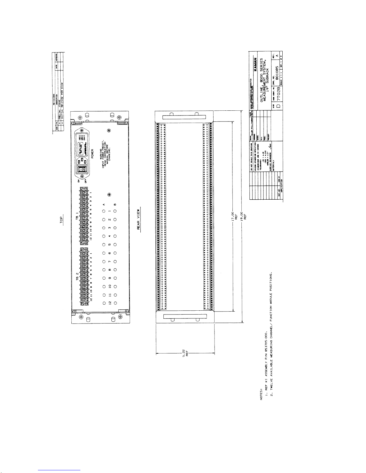
fig. 1 -- Full 19" Subrack Rear/Front Outline drawing 9
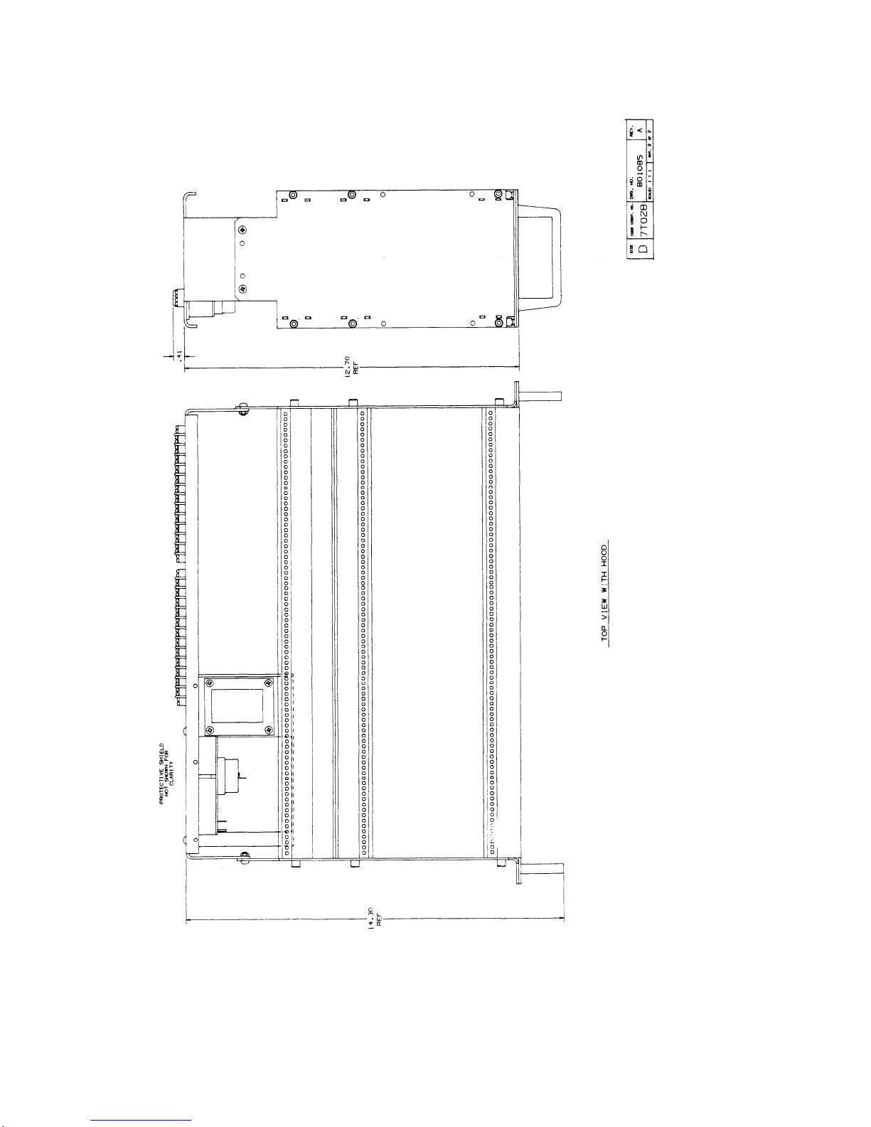
fig. 2 -- Full 19" Subrack Top View Outline Drawing 10
fig. 3 -- Full 19" Subrack Rear/Front with Display 11
fig. 4 -- Full 19" Subrack Rear/Front with Dual Display 12
fig. 5 -- 1/2 Rack with Display Outline Drawing 14
fig. 6 -- 1/2 Rack Outline Drawing 15
fig. 7 -- 3/4 Rack with Display Outline Drawing 16
Table 1 -- Power Supply Specifications 18
fig. 8 -- Power Entry Module 19
fig. 9 -- Accessing the Voltage Selector Card 19
fig. 10 -- Voltage Selector Card Orientation 20
fig. 11 -- Top View of Main board on display. 22
fig. 12 -- Physical Eurocard Pin Locations 23
Table 2 -- Electrical Standards for Pinout 24
fig. 13 -- Single Coil Coaxial 25
fig. 14 -- Dual Coil Coaxial 25
fig. 15 -- Back Plane Template 28
fig. 16 -- Power Entry Module 29
Table 3 -- Terminal Block Labeling 30
fig. 17 -- Back Panel Sensor Inputs 31
fig. 18 -- Typical Module Side Panel Labeling 32
fig. 19 -- Single 1/8 DIN Mounting Panel 814873-001 33
fig. 20 -- Dual 1/8 DIN Mounting Panel 814873-002 34
fig. 21 -- MCD 8000 Front Panel 35
Table 4 -- Displayed Outputs 35
fig. 22 -- MCD 8000 Input Wiring 36
fig. 23 -- MCD 8000 Power Wiring 36
fig. 24 -- Voltage/Current Input Dip Switch 38
fig. 25 -- Diodes For Loop Continuity in Current Mode 38
fig. 26 -- MCD 8000 Adjustment Switches 40
fig. 27 -- Process/Scaling Dip Switch 40
fig. 28 -- Button Function Legend 42
Table 5 -- MCD-8000 Error Message Table 42
Table 6 -- Series 8000 Sensor Family 43
fig. 29 -- Basic Measuring Channel 44
fig. 30 -- Module Reference Dimensions 45
fig. 31 -- VC8000 Voltage to Current Converter 46
fig. 32 -- SC8000 Summation/Comparator 47
fig. 33 -- DY8000 Dynamic Module 48
fig. 34 -- SP8000 Dual Set Point 49

7
Getting Started Quickly
The Series 8000 rack systems are typically prewired and set up at the factory with all
measuring channels and function cards installed. To get started with the 8000 system you will
need to:
aInstall the sensors in the application or cal fixture
bConnect the sensors to the enclosure (see page 30)
cConnect the power cord and turn on the unit
dIf you have a display see page 32
eIf you have no display see page 29 on back panel I/O
As with any complex electronics system you should thoroughly familiarize yourself with all
manuals dealing with the product. Included with the system are the appropriate manuals for
any measuring channels and function cards purchased. Please refer to these manuals for
specific information.
Warning: The integral power supply in racks utilize high voltage
(120 or 240VAC). Unplug the unit before servicing.

8
Series 8000 Enclosures
Subracks
The subrack is a 19" wide frame having solid side panels and horizontal rails across the top
and bottom to hold the system modules in place. Use of a subrack enables you to install your
Series 8000 system into a standard 19" test equipment rack, or bolt it into a NEMA enclosure.
The subrack has a built in 120VAC/240VAC selectable power supply to provide +/-15VDC at 1
amp. The subrack also can be configured with either one or two MCD 8000 display modules
that have up to six selectable inputs. The display modules draw no current from the +/-15 volt
supply.
Full 19" Sub-Racks - 3U/84HP Instrumentation Subrack
Part Number Configuration
853705-000 No display meter, 12 available positions
853705-001 One display meter, 9 available positions
853705-002 Two display meters, 9 available positions

9
fig.1 – Full 19” Subrack Rear/Front Outline Drawing

10
Fig. 2 – Full 19” Subrack Top View Outline Drawing

11
fig. 3 – Full 19” Subrack Rear/Front with Display

12
fig. 4 – Full 19” Subrack Rear/Front with Dual Display

13
Instrument Enclosure
The instrument case is a fully enclosed stand-alone enclosure for your series 8000 system with
a tilt bar to elevate the front of the case. The subrack has a built in 120VAC/240VAC
selectable power supply to provide +/-15VDC at 500 milliamp. The subrack also can be
configured with either one or two MCD 8000 display modules that have up to six
selectable inputs. The display modules draw no current from the +/-15DC volt supply.
1/2 rack enclosures - 3U/42HP Instrumentation enclosure
Part Number Configuration
853704-000 No display meter, 6 available positions
853704-001 One display meter, 3 available positions
3/4 rack enclosures - 3U/63HP Instrumentation enclosure
Part Number Configuration
853723-001 One display meter, 6 available positions

14
fig.5 – ½ Rack with Display Outline Drawing

15
fig. 6 – ½ Rack Outline Drawing

16
fig. 7 – ¾ Rack with Display Outline Drawing

17
NEMA
The NEMA 12 configuration is an 8"x8"x4" continuous hinge enclosure. It can contain either 1
or 2 synchronized measuring channels and an optional function card. An optional integral
power supply and/or display is available. In the NEMA the modules do not have separate
enclosures. This configuration is not described further in this manual, please refer to the NEMA
manual PN 860060 for further information on the NEMA enclosure.
PN Configuration
853638-001 Standard NEMA
853639-001 NEMA with internal 120VAC power supply
853640-001 NEMA with display
853641-001 NEMA with 120VAC PS and display
853639-001E NEMA with 240 VAC power supply
853641-001E NEMA with 240 VAC power supply and display

18
Integral Power Supply
Warning: The integral power supply in racks utilize high voltage
(120 or 240VAC). Unplug the unit before servicing.
The power supply for the series 8000 rack enclosures are integral to the chassis and mounted
on the back panel for better heat dissipation. All of the Series 8000 power supplies provide a
+/-15VDC+/-.5V linear regulated output for low noise operation. The available current is
500mA per side in the 1/2 and 3/4 rack configurations and 1A per side in full rack
configurations. Most measuring channels and function cards from Kaman typically draw less
than 70mA per side. When adding additional function cards or measuring channels to the unit
you should check on the actual current amount by referring to the specifications on each module
and adding up the total current draw from the power supply. For example, if you had 10
measuring channels you should allow for the supply to be able to handle 700mA (full rack
configuration). The MCD-8000 or other 1/8 DIN display modules are powered directly off the
AC input and therefore draw no current from the integral supplies. The power supply
specifications are summarized in table 1 below:
Full 19" Sub-Racks - 3U/84HP Instrumentation Subrack
Input Power: 115VAC +/-10%, 50-60 Hz, .5A fuse
230 VAC +/-10%, 50-60Hz, .25A fuse
Output Voltage: +/-15VDC +/-.5V
Output Current: 1A per side
3/4 rack enclosures - 3U/63HP Instrumentation enclosure
Input Power: 115VAC +/-10%, 50-60 Hz, .5A fuse
230 VAC +/-10%, 50-60Hz, .25A fuse
Output Voltage: +/-15VDC +/-.5V
Output Current: .5A per side
1/2 rack enclosures - 3U/42HP Instrumentation enclosure
Input Power: 115VAC +/-10%, 50-60 Hz, .5A fuse
230 VAC +/-10%, 50-60Hz, .25A fuse
Output Voltage: +/-15VDC +/-.5V
Output Current: .5A per side
Table 1 -- Power Supply Specifications;

19
Input Voltage Selection (120VAC/240VAC)
Warning: When you change the input voltage on the rear panel
you must also change the MCD 8000 input voltage
or you may damage the unit.
Warning: The integral power supply in racks utilize high voltage
(120 or 240VAC). Unplug the unit before servicing.
To change the input voltage you must first select the proper input voltage on the power entry
module on the unit. To change the selected voltage:
aOpen the cover using a small blade screwdriver or similar tool. Set aside
the cover/fuse block assembly and pull the voltage selector card straight
out of the housing. See fig. 9 on accessing the voltage selector card.
fig. 8 -- Power Entry Module;
fig. 9 -- Accessing the Voltage Selector Card;

20
bUsing the indicator pin orient the selector card so that the desired
voltage is readable at the bottom. Orient the indicator pin to point up
when the desired voltage is readable at bottom ( note that when indicator
pin is fixed, successive voltages are selected by rotating the card 90o
clockwise). See fig. 10 for voltage selector orientation.
cInsert voltage selector card into housing with printed side of card facing
toward IEC connector and edge containing the desired voltage first.
Replace cover and verify that indicator pin shows the desired voltage.
fig. 10 -- Voltage Selector Card Orientation;
Table of contents