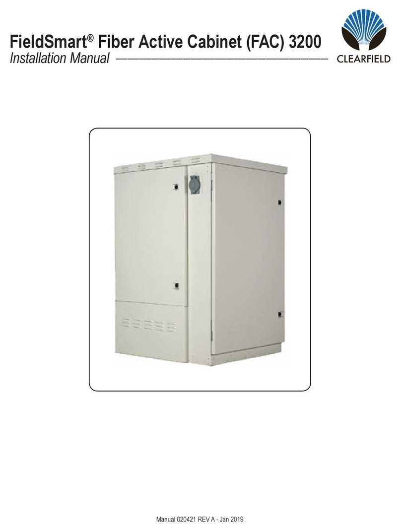
Clearfield FieldSmart Fiber Active Cabinet 400 User manual

FieldSmart®Fiber Active Cabinet (FAC) 400
Installation Manual ______________________________________________________
Manual 020419 REV A - Feb 2019

FieldSmart®Fiber Active Cabinet (FAC) 400
Installation Manual _________________________________________________________
Proprietary Information: Not for use or disclosure except by written agreement with Cleareld.
2
Table of Contents
About This Guide 5
Chapter 1: Fiber Active Cabinet 400 Product Overview 6
Cabinet Description 7
Cabinet Features 8
Cabinet Options 9
Cabinet Dimensions and Weights 10
Cabinet Views 11
Chapter 2: Installation Considerations 13
Installation Process Overview 14
Installation Guidelines 15
Space Requirements 16
General Safety Recommendations 17
Installation Kit 18
User-Supplied Items 19
Cabling Requirements 20
Chapter 3: Preparing the Installation Site 21
Installing a Ground Circuit 22
Constructing a Concrete Pad 25
Pad Construction Guidelines 25
Assembling the Cast-In-Place Template 28
Preparing the Site 29
Casting the Pad 30
Installing a Pre-Cast Concrete Pad 31
Pre-Cast Pad Requirements 31
Preparing the Site 34
Installing a Pre-Cast Pad 35
Installing a Pole-Mount Kit: Local Power with 60 Ah Battery
Base(s) 36
Pole Mounting Guidelines 36
Preparing the Site 39
Installing the Pole-Mount Kit 39
Installing a Wall-Mount Kit: Local Power with 60 Ah Battery
Base(s) 43
Wall/H-Frame Mounting Guidelines 43
Preparing the Site 47
Installing the Wall-Mount Kit 47

3
FieldSmart®Fiber Active Cabinet (FAC) 400
__________________________________________________________ Installation Manual
Direct: 763.476.6866 • National: 800.422.2537 • www.SeeCleareld.com • [email protected]
Manual 020419 REV A - Feb 2019
Installing a Foundation Vault 50
Foundation Vault Requirements 50
Preparing the Site 53
Installing the Foundation Vault 54
Chapter 4: Installing the Cabinet 55
Unpacking the Cabinet 56
Operating Cabinet Doors 57
Preparing the Cabinet for Installation 59
Installing the Cabinet on a Concrete Pad 60
Installing the Cabinet on a Wall or H-Frame 63
Installing the Cabinet on a Pole: Local Power with 60 Ah Battery
Base(s) 65
Installing the Cabinet on a Foundation Vault 67
Removing the Lifting Details 69
Chapter 5: Installing Local AC Power 70
Installing the Cabinet Ground Connection 71
Installing AC Power (220-240 VAC) 73
Chapter 6: Installing and Splicing Outside Plant Cables 75
Bonding Cable Sheaths 76
Installing Fiber Cable 77
Installing Outside Plant Fiber Cable 77
Splicing Fibers 79
Connecting Fibers to the Equipment 79
Installing Metallic Cables 80
Installing Outside Plant Metallic Cables 80
Splicing Metallic Cables 81
Installing 5-Pin Protection Modules 82
Sealing Cable Entry Locations 82
Chapter 7: Turning Up the Cabinet Power System 83
Turning Up the Power System 84
Checking the Ground Connection 84
Checking the AC Power Supply Voltage 85
Installing the Rectier Modules (Alpha Cordex Rectier
Option) 86
Installing and Testing Batteries 88

FieldSmart®Fiber Active Cabinet (FAC) 400
Installation Manual _________________________________________________________
Proprietary Information: Not for use or disclosure except by written agreement with Cleareld.
4
Chapter 8: Installing Equipment, Options and Adding Capacity 97
Installing a Protection Mounting Frame 98
Installing a Protection Block 100
Installing a Cross-Connect Panel 102
Installing a Battery Compartment Riser 104
Installing a Battery Heater 105
Installing a Generator Connector 108
Installing Fiber Management Options 110
Installing a 48-Position Fiber Distribution Panel 111
Installing the Fiber Management Accessories 114
Installing a 1:32 Splitter and Integration Kit 116
Chapter 9: Cabinet Maintenance 120
Routine Maintenance 121
Checking Cabinet Surfaces 121
Checking Electrical Components 122
Checking Cable Connections 123
Checking the Heat Exchanger 124
Battery Maintenance 125
Replacing Parts and Equipment 127
Removing a Cabinet Door 127
Installing a Cabinet Door 128
Replacing the Cabinet Roof 130
Replacing AC Breakers 131
Replacing Rectier Modules (Alpha Cordex Rectier Op-
tion) 132
Replacing Batteries 133
Replacing a Battery Heater 134
Appendix A: Reference Information 135
Specications 136
Optional Alpha Cordex HP Rectier Alarms and Controller Set-
tings 137
Supported Batteries 137
Wiring Diagrams 137
Standard Warranty 138
Proprietary Notice 139
Technical Support 139

5
FieldSmart®Fiber Active Cabinet (FAC) 400
__________________________________________________________ Installation Manual
Direct: 763.476.6866 • National: 800.422.2537 • www.SeeCleareld.com • [email protected]
Manual 020419 REV A - Feb 2019
This document is intended for use by network planning engineers, outside plant engineers, eld support personnel, and craft
personnel responsible for cabinet installation, splicing, equipment installation, and maintenance.
Intended Audiences
This document provides a general installation practice for the Cleareld FAC 400 outdoor cabinet. This document also
provides a general description of the cabinet and its subsystems, guidance for planning, site preparation, power installation,
splicing to the outside plant, component installation and expansion, and cabinet maintenance.
About This Guide
This equipment has been tested and found to comply with the limits for a Class A digital device, pursuant to Part 15 of the
FCC rules. These limits are designed to provide reasonable protection against harmful interference when the equipment is
operated in a commercial environment. This equipment generates, uses, and can radiate radio frequency energy, and, if not
installed and used in accordance with the instruction manual, may cause interference to radio communications. Operation of
this equipment in a residential area may cause harmful interference; the user will be required to correct the interference at
his expense.
Federal Communications Commission (FCC) Statement
This document uses the following safety notice conventions.
Safety Notices
DANGER! Danger indicates the presence of a hazard that will cause severe personal injury or death
if not avoided.
WARNING! Danger indicates the presence of a hazard that will cause severe personal injury or death
if not avoided.
CAUTION! Danger indicates the presence of a hazard that will cause severe personal injury or death
if not avoided.
ALERT! Danger indicates the presence of a hazard that will cause severe personal injury or death
if not avoided.
DANGER! CLASS 1 LASER PRODUCT. INVISIBLE LASER RADIATION MAY BE PRESENT
Danger indicates the presence of a hazard that will cause severe personal injury or death
if not avoided.

FieldSmart®Fiber Active Cabinet (FAC) 400
Installation Manual _________________________________________________________
Proprietary Information: Not for use or disclosure except by written agreement with Cleareld.
6
Chapter 1: Fiber Active Cabinet 400 Product Overview
This chapter provides a general description of the Cleareld FAC 400 outdoor cabinet, including its standard features and
options.
Topics Covered
This chapter provides a general description of the Cleareld FAC 400 outdoor cabinet, including its standard features and
options.
• A description of the FAC 400 cabinet.
• A list of standard cabinet features.
• A list of cabinet options.
• Listed cabinet dimensions and weights
• A Views of the cabinet compartment.

7
FieldSmart®Fiber Active Cabinet (FAC) 400
__________________________________________________________ Installation Manual
Direct: 763.476.6866 • National: 800.422.2537 • www.SeeCleareld.com • [email protected]
Manual 020419 REV A - Feb 2019
Cabinet Description
The Cleareld FAC 400 cabinet is an environmentally-controlled outdoor enclosure designed to house and protect network
electronics equipment. Use the FAC 400 to provide services from a remote node location deep inside the customer serving
area, beyond the direct reach of the carrier Central Ofce.
The FAC 400 cabinet has a single compartment that houses electronics equipment together with ber and copper plant
terminations, enabling deployment of multiple applications from one node. The electronics area is equipped with a
vertically-oriented 19-inch equipment rack that provides 4 RU of mounting space.
The FAC 400 supports local power congurations. The local power conguration includes an additional base compartment
to support battery reserve power.
The modular design of the FAC 400 enables incremental expansion of system capacity, lowering initial deployment costs
while maintaining the capacity for future growth. Modular components designed for expansion include compact service
units, ber management capacity, copper line protection, DC power modules, and cooling elements.

FieldSmart®Fiber Active Cabinet (FAC) 400
Installation Manual _________________________________________________________
Proprietary Information: Not for use or disclosure except by written agreement with Cleareld.
8
Cabinet Features
Standard features of the FAC 400 cabinet include:
Enclosure Design
• Environmentally sealed design protects from dust and water intrusion
• GR-487 compliant and UL-67 spec
• Environmentally rated from -40C to +46C (per GR-487)
Equipment Support
• 19-inch equipment rack provides 4 RU of mounting space
• Mechanical support for ber and copper plant terminations
• Modular, scalable copper line protection (50-pair block increments, 300 pairs maximum)
• Door-mounted 300W heat exchanger
Power (Local)
Standard features for the local power conguration include:
• 240 VAC load center (ETL-listed); 30 Amp capacity
• AC main/service disconnect breaker
• AC surge suppressor
• Duplex convenience outlet (GFCI protected)
• FAC 400 Power Hub compact DC rectier shelf
• Fuse-protected DC supply to equipment
• Low voltage DC disconnect (-42 VDC)
• Battery backup in separate vented compartment
• Up to 62 Ah battery reserve capacity (breaker-protected); up to 124 Ah capacity with second-string riser option

9
FieldSmart®Fiber Active Cabinet (FAC) 400
__________________________________________________________ Installation Manual
Direct: 763.476.6866 • National: 800.422.2537 • www.SeeCleareld.com • [email protected]
Manual 020419 REV A - Feb 2019
Cabinet Options
Common options for the FAC 400 cabinet include:
Enclosure Mounting
• Concrete pad mounting: pre-cast or site-cast pad (using Cleareld pad template)
• Pole, wall, or frame mounting (using Cleareld mounting kits)
• Foundation vault mounting (third-party supplied)
Copper Protection & Trunking, Splicing & Distribution, Cable Management
• High density ber management options (48- and 96-position ber distribution panels, 1:32 PON splitters,
management accessories), up to 192 ports of internal distribution
• Copper line protection for up to 288 lines; MS2 or 710 interface connectors
• Cross-connect panel with MS2 or 710 interface connectors; 2:1 subscriber-to-equipment line counts: 300 pair (200:100)
• Cleareld xPAK low count ber distribution with LGX mounting
Power
Local power support (commercial AC power supply); additional options include:
• 110/120 and 220/240 VAC input
• Generator connector (Hubbell); 30A NEMA twist lock with breaker
Battery Support (local power congurations)
• Northstar or Enersys (OEM) battery string and installation kit (OEM)
• Battery heater kit
• Battery compartment riser (supports second 60 Ah or 62 Ah battery string)

FieldSmart®Fiber Active Cabinet (FAC) 400
Installation Manual _________________________________________________________
Proprietary Information: Not for use or disclosure except by written agreement with Cleareld.
10
Cabinet Dimensions and Weights
The external dimensions of the FAC 400 cabinet are shown below.
Note: Based on the dimensions, the cabinet can withstand 79.5 lbs of wind force.
Dimension Measurement (SAE) Measurement (Metric)
Height:
Local Power 48 inches 122 cm
Width 19.7 inches (60 Ah battery base) 50 cm
Depth 24 inches 61 cm
The approximate weight of the FAC 400 cabinet is shown below.
Conguration Weight (SAE) Weight (Metric)
Local power (60 Ah batteries), 96 copper lines 222 lb 101 kg

11
FieldSmart®Fiber Active Cabinet (FAC) 400
__________________________________________________________ Installation Manual
Direct: 763.476.6866 • National: 800.422.2537 • www.SeeCleareld.com • [email protected]
Manual 020419 REV A - Feb 2019
Cabinet Views
Views of the FAC 400 cabinet follow.
Front Compartment
The front compartment provides access to the electronics equipment, cabinet power system, and ber management or
copper line protection. The cabinet power system consists of an AC load center. For ber access, the ber management
accessories may vary greatly according to the ordered options. For copper access, the line protection may include up to six
50-pair protection blocks.
FAC 400 Front
(local power)

FieldSmart®Fiber Active Cabinet (FAC) 400
Installation Manual _________________________________________________________
Proprietary Information: Not for use or disclosure except by written agreement with Cleareld.
12
Side Compartment
The side compartment provides access to the cable entry and splice locations and the main ground bar. The side compart-
ment also houses an optional cross-connect panel for copper access systems.
Battery Compartment (Local Power)
Cabinets congured for local power include a battery base compartment for housing one string of front-access
VRLA batteries.
Battery compartment interior dimensions (for batteries): 10.3 (H) x 18.6 (W) x 11.5 (D) inches (26.2 x 47.2 x 29.2 cm)
Note: Batteries t compactly in the 60 Ah base. Use only approved batteries to meet seismic compliance and follow the
installation instructions to ensure a proper t in the compartment.
FAC 400 Side

13
FieldSmart®Fiber Active Cabinet (FAC) 400
__________________________________________________________ Installation Manual
Direct: 763.476.6866 • National: 800.422.2537 • www.SeeCleareld.com • [email protected]
Manual 020419 REV A - Feb 2019
Chapter 2: Installation Considerations
This chapter provides general considerations for cabinet installation. Review this information before starting the cabinet
installation process.
Topics Covered
This chapter covers the following topics:
• Installation process overview
• Installation guidelines
• Space requirements
• General safety recommendations
• Installation kit contents
• User-supplied items
• Cabling requirements

FieldSmart®Fiber Active Cabinet (FAC) 400
Installation Manual _________________________________________________________
Proprietary Information: Not for use or disclosure except by written agreement with Cleareld.
14
Installation Process Overview
The cabinet installation process involves the following high-level steps:

15
FieldSmart®Fiber Active Cabinet (FAC) 400
__________________________________________________________ Installation Manual
Direct: 763.476.6866 • National: 800.422.2537 • www.SeeCleareld.com • [email protected]
Manual 020419 REV A - Feb 2019
General Guidelines
Follow these general guidelines and practices:
• Read this document completely before starting any installation activities.
• Only qualied personnel should perform the procedures described in this document.
• Follow standard safety precautions when performing installation and maintenance tasks.
• Always wear standard safety gear when performing installation and maintenance tasks (hard hats/safety headgear, eye
protection, insulated gloves).
• For safety, keep bystanders and other unauthorized personnel away from work operations at all times.
• Do not perform installation activities when the threat of lightning is present.
• Warning! - Seal all cable entry locations immediately after the cabinet is installed to prevent ground moisture from
condensing inside the cabinet and damaging equipment.
Installation Guidelines
Review the following guidelines before starting installation activities.
Site Selection
The location of a cabinet installation site should be carefully planned in advance. Consider the following factors when
selecting an installation site:
1. Functional requirements
• Suitable terrain. Whenever possible, the cabinet should be located in an area with a rm at soil surface that does
not require extensive earth work. The location should not be constantly damp or prone to ooding. Check soil maps of
potential sites for subsurface conditions.
• Grounding properties. Grounding properties. The earth at the cabinet location should have a low ground impedance
to provide an effective grounding system for lightning protection and safety. Perform ground testing to determine the
grounding requirements.
• Safety. Whenever possible, the cabinet should be located on vacant property away from motor trafc to reduce injury risks
to maintenance personnel or damage to equipment. On streets and highways, avoid locations near busy intersections or
curves in the road. Erecting guard rails or concrete pillars can provide additional safety barriers against motor trafc.
• Solar exposure. Whenever possible in hot or warm climates, avoid locations with heavy exposure to direct afternoon
sun, so as to maximize the life of electronics equipment in the cabinet. High outdoor temperatures and heavy solar
exposure raise temperatures inside cabinets, a condition that can reduce the life span of equipment. Conversely, wind
exposure improves thermal conditions in a cabinet, so locations that do not block wind are desirable.
2. Accessibility requirements:
• Easement size. Select a location with an easement that provides enough space to walk around the perimeter of the
cabinet with its doors open.
• Right-of-Way. Secure a permanent location on private property, whenever possible. Obtain a rm right-of-way agree-
ment that includes right of access. Avoid locations in public rights-of-way.
• Electrical access. Locally-powered cabinets must have access to commercial AC power. Verify the availability of AC
service at potential cabinet locations.
• Parking. Whenever possible, the cabinet should be located in an area that provides sufcient parking space for
• installation and maintenance vehicles.

FieldSmart®Fiber Active Cabinet (FAC) 400
Installation Manual _________________________________________________________
Proprietary Information: Not for use or disclosure except by written agreement with Cleareld.
16
Space Requirements
The illustration below shows the cabinet clearance and space requirements.
The minimum clearance area around the cabinet site must be free of permanent impediments to allow full swing of the
cabinet doors. This area must be kept clear of obstructions at all times to provide adequate access for all installation and
maintenance activities.
FAC 400

17
FieldSmart®Fiber Active Cabinet (FAC) 400
__________________________________________________________ Installation Manual
Direct: 763.476.6866 • National: 800.422.2537 • www.SeeCleareld.com • [email protected]
Manual 020419 REV A - Feb 2019
DANGER! Risk of high power current surge and electric shock. Read and understand all power procedures
before performing tasks. Take necessary precautions and use appropriate insulated tools when working with
power. This equipment must be installed, operated, and serviced by qualied technical personnel only.
WARNING! Only trained, qualied technical personnel should perform the procedures described in this doc-
ument. These procedures involve potentially hazardous activities, including handling of heavy equipment and
exposure to high electrical energy, which could cause injury to untrained personnel.
WARNING! The cabinet and its components are heavy. Handle with care to avoid personal injury or damage
to the equipment.
DANGER! CLASS 1 LASER PRODUCT. INVISIBLE LASER RADIATION MAY BE PRESENT.
Fiber optic radiation can cause severe eye damage or blindness. Do not look into the open end of an
optical ber.
General Safety Recommendations
ESD ALERT! Beware of electrostatic discharge. Follow standard ESD precautions. Always wear a grounded
ESD wristband to avoid damaging the electronic equipment.
CAUTION! Batteries contain a stored charge. Handle batteries with care.

FieldSmart®Fiber Active Cabinet (FAC) 400
Installation Manual _________________________________________________________
Proprietary Information: Not for use or disclosure except by written agreement with Cleareld.
18
Installation Kit
Cleareld supplies an installation kit with the cabinet that includes materials required for installation. The installation kit
contents are listed below. Check to verify that your kit contains all of the listed items.:
Qty Item Description
1Telco hex key, 5/16”
1Isolation mat
4Hex nuts (for mounting)
8Flat washers (for mounting)
4Split lock washers (for mounting)
41/2” hex head bolts (for mounting)

19
FieldSmart®Fiber Active Cabinet (FAC) 400
__________________________________________________________ Installation Manual
Direct: 763.476.6866 • National: 800.422.2537 • www.SeeCleareld.com • [email protected]
Manual 020419 REV A - Feb 2019
User-Supplied Items
Supply the following items for cabinet installation.
Tools
Bring the following tools to the installation site:
• Power drill with universal socket and screwdriver bit sets
• Socket wrench/nut driver set (standard)
• Box wrench set (standard)
• Screwdriver set (standard)
• Beam Level
• Insulated needle-nose pliers
• Wire stripper
• Compression crimping tool
• Fiber cleaver
• Fiber splicer
• Modular MS2 or 710 splicing tool
• RB Razor-Sharp Cutting Edge knife, or another similar tool
Materials
Bring the following materials to the installation site:
• Leveling shims
• Silicone sealant
• MS2 or 710 connectors for copper line splicing
• Strain relief for #6-8 AWG wiring.
Equipment
Bring the following equipment to the installation site:
• Digital multi-meter
• Optical power meter
• Digital multi-function test set

FieldSmart®Fiber Active Cabinet (FAC) 400
Installation Manual _________________________________________________________
Proprietary Information: Not for use or disclosure except by written agreement with Cleareld.
20
Cabling Requirements
Cables supplied to the cabinet must meet the following minimum requirements.
Note: Local climatic conditions, site conditions, or local practices may require adjustments to cabling requirements.
Function Facility Requirements
Power
Ground Copper 6 AWG solid bare copper wire (to earth ground circuit);
terminates to ground bar with screw lug
AC
(local power) Copper 8–10 AWG stranded copper; Follow National Electric Code (NEC) and local codes
Table of contents
Other Clearfield Enclosure manuals
Popular Enclosure manuals by other brands
HYDROCOWL
HYDROCOWL Safe-t-Cover 300DS Series Assembly instructions
Sonnet
Sonnet FUSION D400RAID user guide
Rasilient
Rasilient PS390e user manual
Rosewill
Rosewill RX35-AT-SC BLK user manual
SIIG
SIIG USB 3.0 to SATA Hard Drive with SD reader Enclosure -... User reference guide
StorCase Technology
StorCase Technology Data Express DE100i-SWC user guide

