3
Quick Guide
1. Read the signal strength on the module's Light Emitting Diodes (LEDs) (Min.
two must be switched on).
2. If the signal strength is below 2, an external antenna must be installed*.
3. The external antenna must be placed in a location that optimises the
reception of the signal. Change the position of the antenna until the best
position has been found.
4. Before leaving the installation, test the signal strength by SMS (=signal#).
Make sure that the meter cabinet and doors are closed before sending the
SMS.
* An external Triangle antenna must always be mounted on GSM8i RF 3G
(Order No.: 6699407 or 6699408)
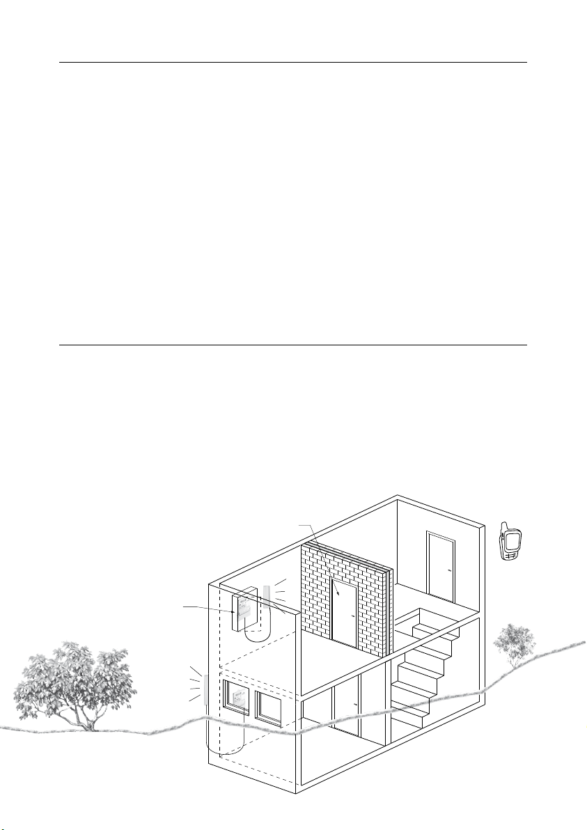
Tips
• Always install an external antenna when installing the unit in a metal cabi-
net. The antenna must be placed outside the cabinet.
• Use dual-band GSM antennas to optimise the performance.
• Note that fire doors, concrete and metal plates disturb and weaken the GSM
signal.
• It is possible to order directional antennas for areas with very poor signal
conditions (please contact Kamstrup A/S for further information).
SMS
Asennettaessa mittari
metallikoteloon, varmista,
että antenni sijoitetaan
kotelon ulkopuolelle.
Varmista, että kaikki ovet ja
kotelot on suljettu ennen
SMS-komennon lähettämistä.
Palo-ovi
Mittarin sijaitessa maanpinnan
alapuolella (esim. kellarissa),
asennetaan lisäantenni lähelle
ikkunaa tai rakennuksen
ulkopuolelle.
Metallikotelo
CONTENTS
1 Description ................................................4
1.1 Description of GSM8i 3G.....................................4
1.2 Description of GSM8i RF 3G ..................................5
1.3 Using GSM8i 3G. . . . . . . . . . . . . . . . . . . . . . . . . . . . . . . . . . . . . . . . . . . .5
2 Mounting GSM8i 3G .........................................6
2.1 Mounting order ............................................6
3 Mounting of GSM8i RF 3G ....................................7
3.1 Mounting order ............................................7
4 Light Emitting Diodes ........................................8
4.1 Positioning of LEDs .........................................8
4.2 Start-up ..................................................8
4.2.1 Is checking the SIM card....................................8
4.2.2 Is connecting to the network ................................8
4.2.3 Connected to 2G/3G network and meter .......................9
4.2.4 Signal strength indicator ...................................9
4.2.5 Error indication ...........................................9
4.2.6 External antenna ..........................................9
5 SIM card..................................................10
5.1 Mounting the SIM card .................................... 10
5.2 SIM card requirements .................................... 10
6 Mounting of external antenna (to be ordered separately)..........11
7 External antenna on GSM8i 3G ...............................12
8 External antenna on GSM8i RF 3G.............................13
8.1 Antenna for GSM8i RF 3G .................................. 14
8.2 Mounting GSM8i RF 3G in Kamstrup electricity meters........... 14
8.3 Kamstrup 382 - type 685-282-zz-zz.......................... 15
8.4 Kamstrup 382 - type 685-382-zz-zz.......................... 16
8.5 Kamstrup 351 Combi - type 685-251-xx-xx-xxx................. 17
8.6 Kamstrup 351 Combi - type 685-351-xx-xx-xxx................. 18
9 Error detection help ........................................19
10 SMS commands............................................20