Kanardia INDU Airspee User manual

INDU Airspeed — Manual
Kanardia d.o.o.
June 2016
©
Kanardia d.o.o.
Revision 1.0

INDU Airspeed — Manual
Contact Information
Publisher and producer:
Kanardia d.o.o.
Ulica heroja Rojˇska 70
SI-3000
Slovenia
Tel: +386 40 360 512
Email: info@kanardia.eu
A lot of useful and recent information can be also found on the Internet. See http://www.
kanardia.eu for more details.
Copyright
This document is published under the Creative Commons, Attribution-ShareAlike 3.0 Un-
ported licence. Full license is available on http://creativecommons.org/licenses/by-sa/
3.0/legalcode web page and a bit more human readable summary is given on http:
//creativecommons.org/licenses/by-sa/3.0/. In short, the license gives you right to
copy, reproduce and modify this document if:
you cite Kanardia d.o.o. as the author of the original work,
you distribute the resulting work only under the same or similar license to this one.
Credits
This document was written using TeTeX (L
A
T
E
X) based document creation system using
Kile running on Linux operating system. Most of the figures were drawn using Open Office
Draw and Inkscape applications. Photos and scanned material was processed using Gimp.All
document sources are freely available on request under the licence mentioned above and can
be obtained by email. Please send requests to info@kanardia.eu.
Revision History
The following table shows the revision history of this document.
Rev. Date Description
1.0 June 2016 Initial release
2
©
Kanardia 2016

INDU Airspeed — Manual CONTENTS
Contents
1 Introduction 4
1.1 GeneralDescription ................................ 4
1.2 TechnicalSpecification............................... 4
1.3 Options ....................................... 5
1.3.1 Scale..................................... 5
1.3.2 Display ................................... 6
1.3.3 VisualWarnings .............................. 7
2 Installation & Maintenance 8
2.1 MountingDimensions ............................... 8
2.2 Connections..................................... 8
2.2.1 Static Pressure - Pst ............................ 8
2.2.2 Total Pressure - Ptot ........................... 9
2.2.3 CAN Bus - CAN ............................... 9
2.2.4 Power - POWER ............................... 9
2.2.5 Outside Air Temperature - OAT ...................... 9
2.3 Maintenance .................................... 10
2.4 Repair........................................ 10
2.5 SensorOffset .................................... 10
3 Limited Conditions 12
3.1 TwoYearsWarranty................................ 12
3.2 TSO Information — Limited Operation . . . . . . . . . . . . . . . . . . . . . 13
3
©
Kanardia 2016

INDU Airspeed — Manual 1. Introduction
1 Introduction
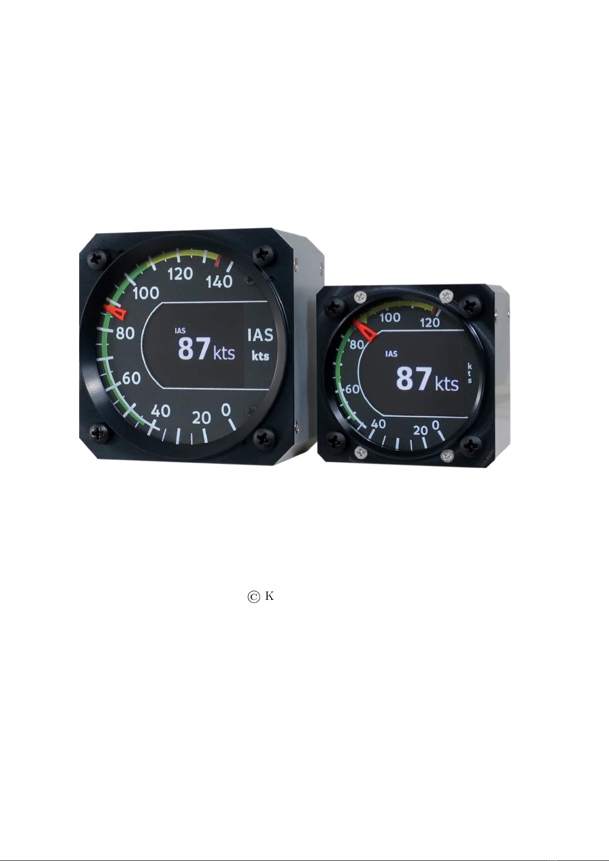
First of all, we would like to thank you for purchasing our device. Indu airspeed is an electronic
device, which mimics classical airspeed construction and combines it with the state of the art
electronics. This results in the best of both worlds; a perfect and intuitive analogue reading
combined with high precision of modern electronics.
This manual describes the technical description of the unit, installation and operation.
1.1 General Description
The airspeed is an electromechanical device. It consists of high precision electronic differen-
tial pressure sensor, which provides dynamic air pressure information in digital form. The
electronics reads the sensor and drives stepper motor turning a needle. Airspeed information
is also shown on a colour LCD display. When connected to a CAN bus the airspeed outputs
airspeed and OAT 1data which can be used by other Kanardia devices.
Display is divided linearly in 230◦scale with colour LCD display in the center. Scale is custom
made and must be specified when ordering the device.
There is a special version1of airspeed indicator that can display true airspeed (TAS) and
outside air temperature (OAT) information on LCD display. This requires an external OAT
probe to be connected to airspeed and an Indu Altimeter to be present on same CAN bus.
1.2 Technical Specification
Table 1 shows some basic technical specification of Indu airspeed.
Description Value
Weight 57 mm: 160 g (cca 210 g with OAT probe)
80 mm: 200 g (cca 250 g with OAT probe)
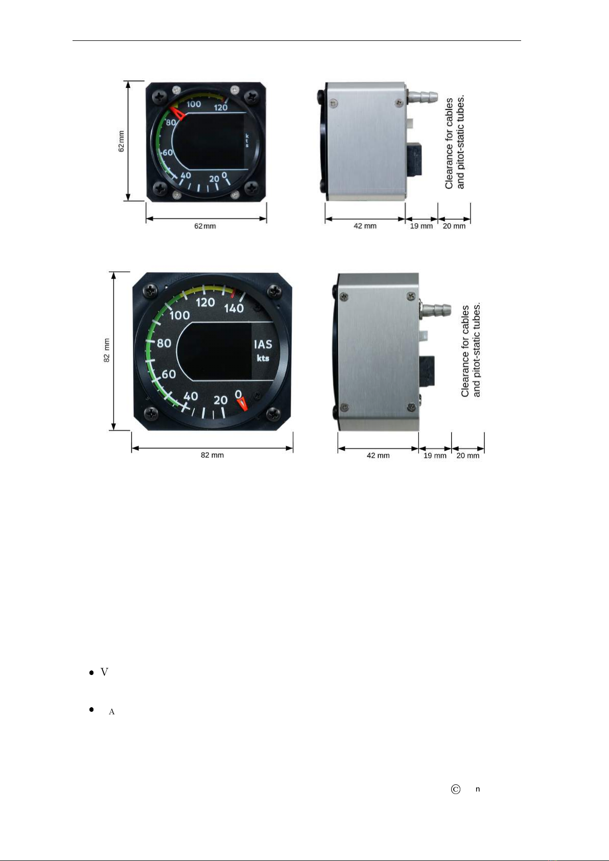
Size 57 mm: 62 x 62 x 42 (61 with connectors) mm
80 mm: 82 x 82 x 42 (61 with connectors) mm
Operational voltage 6 to 32 V
Power consumption 1.26 W
Current 105 mA at 12 V
53 mA at 24 V
Operating temperature -30 ◦Cto +85 ◦C
Humidity 30 % to 90 %, non condensing
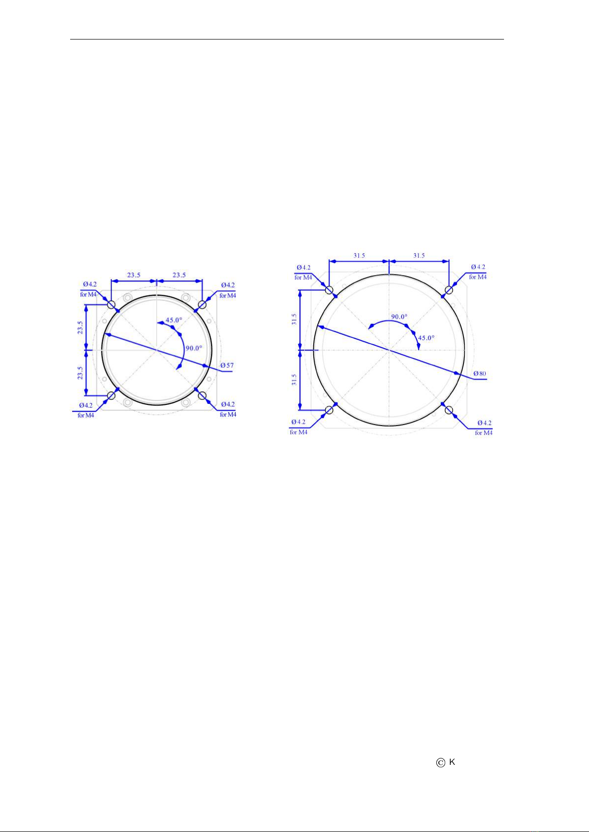
Panel hole 80 mm (3.15 inch) diameter, standard fit
Airspeed sensor 12 bit, 0 to 50 hPa, 325 km/h, resolution less than 0.1 km/h
Option1: 0 to 100 hPa, 460 km/h
OAT 12 bit, range -55 to 125 ◦C, 0.5 ◦Caccuracy
Communication CAN bus, 29 bit header, 500 kbit, Kanardia protocol
Table 1: Basic technical specifications.
1Must be specified at the time of order. Please refer to “INDU Airspeed Ordering Form” for more details.
4
©
Kanardia 2016

INDU Airspeed — Manual 1.3 Options
(a) 57 mm
(b) 80 mm
Figure 1: Front and side view of the airspeed with its principal dimensions.
1.3 Options
1.3.1 Scale
The instrument can be delivered with different scales. Basically, there are no standard scales
and you have to define the scale units and scale markings at the time of order. Scale is then
custom made for each individual order.
Scale holds color-coded markings in order to give the pilot immediate reference. The following
markings are possible:
VNE – Red line on the top of yellow arc. This designates never exceed speed limit.
This is a speed, which should never be exceeded due to the risk of structural failure.
VA– Top of green and bottom of yellow arc. This designates the design maneu-
vering speed. This speed is limited by aircraft structural characteristics at full control
inputs deflecton.
5
©
Kanardia 2016

INDU Airspeed — Manual 1.3 Options
VFE – Top of white arc. This defines maximal extended flap speed. Note that a
different speed limit may be defined for partial extended flap.
VREF – Yellow triangle. The triangle defines the reference speed. This defines the
landing reference speed or threshold crossing speed.
VS1 – Bottom of green arc. Stall speed or minimum steady flight speed for which
the aircraft is still controllable in a specific configuration. This is usually a clean
configuration with flaps retracted. Note that bottom of green arc usually starts at 10%
higher value.
VS0 – Bottom of white arc. Stall speed or minimum flight speed in landing config-
uration. Note that bottom of white arc usually starts at 10% higher value.
Figure 2: A scale example with the markings.
1.3.2 Display
By default instrument displays indicated airspeed information on LCD display. Instruments
with OAT option can be configured to display IAS, OAT and true airspeed2information.
Figure 3 shows all three display configurations. Display configuration must be specified at
the time of order.
2Airspeed instrument must be connected to Indu Altimeter via CAN bus.
6
©
Kanardia 2016

INDU Airspeed — Manual 1.3 Options
(a) Default (b) IAS + OAT (c) IAS + OAT + TAS
Figure 3: Display configurations
1.3.3 Visual Warnings
The instrument can be configured1to show three types of warnings on LCD display:
VAexceeded. Yellow IAS value designates that the IAS value has exceeded the design
maneuvering speed VA(Figure 4a).
VNE exceeded. Red IAS value designates that the IAS value has exceeded the never
exceed speed limit VNE (Figure 4b).
(a) VAexceeded (b) VNE exceeded
Figure 4: Visual warnings
7
©
Kanardia 2016

INDU Airspeed — Manual 2. Installation & Maintenance
2 Installation & Maintenance
The Indu airspeed requires a standard size 57 or 80 mm hole in the instrument panel. The
position of the hole must ensure that the instrument is always visible from the pilot’s per-
spective.
2.1 Mounting Dimensions
The mounting screw holes are located on a circle of 66.5/89 mm diameter. The instrument
is mounted using four screws type M4. To prevent internal stresses, please make sure that
the instrument panel is flat. It is highly recommended that the instrument panel is mounted
using rubber shocks, which reduce the vibrations. Figure 5 illustrates the mounting hole for
both sizes of instrument.
(a) 57 mm
(b) 80 mm
Figure 5: Instrument panel cutout and mounting hole. Note: Figure is not in scale.
2.2 Connections
Figure 6 illustrates all connections at the back side of the instrument.
2.2.1 Static Pressure - Pst
The instrument must be connected to the static pressure source. Static pressure source is
usually obtained from pressure sources located on the fuselage side surfaces or from the static
port on the pitot tube.
Locate the existing tube, cut it at an appropriate place and insert a T junction. Install a
new tube from junction to the instrument.
It is highly recommended to keep the static tubing as short as possible. The tubing must
avoid sharp bends and twists. The tubing must be airtight. Water must not be allowed to
enter the tubing.
It is strongly recommended to label each tube before connecting to instrument. This will
help a lot if you ever have to remove and re-install the instrument.
8
©
Kanardia 2016

INDU Airspeed — Manual 2.2 Connections
(a) 57 mm
(b) 80 mm
Figure 6: Back view of the instrument with connections.
2.2.2 Total Pressure - Ptot
The instrument must be connected to the total pressure source. Total pressure source is
obtained from the total port on the pitot tube.
Same principles as with the static connection apply.
2.2.3 CAN Bus - CAN
Connection to the CAN bus is optional and is not required for the normal operation. When
connected to the bus, airspeed will transmit airspeed and OAT1data to other units connected
to the bus.
Use standard RJ45 ethernet cable to connect it with other Kanardia equipment.
2.2.4 Power - POWER
Connect supplied connector at the back of the airspeed. The connector has a notch on one
side, which protects from wrong orientation.
Connect blue lead to negative (ground) terminal and red lead to positive (+12 to +24 V)
terminal.
2.2.5 Outside Air Temperature - OAT
Outside air temperature (OAT) probe is shipped with airspeed on request. This is a digital
temperature sensor inserted into a threaded aluminium tube. Default OAT cable length is
1.5 meters but other lengths are available on request.
OAT information is required to calculate true airspeed from indicated airspeed and altitude,
as well as to provide you with the outside temperature information.
In order to provide accurate measurements, OAT probe must be installed on a proper place
where the probe is not exposed to the disturbing sources of heat:
9
©
Kanardia 2016

INDU Airspeed — Manual 2.3 Maintenance
engine heat and exhaust heat,
direct sunlight,
heated air exited from cabin.
We also do not recommend installing the probe in the heated cabin area, since the elevated
temperature in the cabin may influence the back side of the probe, though such influence is
usually small.
Please follow these steps to install the OAT probe:
1. Locate a spot in the aircraft taking into account the considerations from above and
drill a φ8 mm hole.
2. Remove the external nut from the probe but keep the washer, internal nut and plastic
insulation tube on the probe.
3. Install the probe into the hole from the interior. Route the cable to the airspeed back
panel.
4. Apply some lock-tight and thread the external nut to the probe. The lock-tight is
necessary to avoid losing the cap due to vibrations.
5. Tighten the internal nut so that the probe sits firmly and apply lock-tight on the nut.
Do not over tight it.
6. Slide the plastic insulation tube over the exposed threads of the probe and cover as
much threads as possible. Shrink the tube using hot air blower. Do not use open flame.
Plastic insulation (shrink) tube also serves as thermal insulation for the sensor located
in the tip.
2.3 Maintenance
No special maintenance is required. A pito-static leak test should be performed annually and
calibration check biannually.
2.4 Repair
The Indu airspeed has no serviceable parts inside. In the case of malfunction, it must be sent
to factory for a repair.
2.5 Sensor Offset
Sensor offset can be tuned with the help of INDU altimeter. Please refer to altimeter manual
for more details.
10
©
Kanardia 2016

INDU Airspeed Ordering Form
2. Scale (refer to section 1.3.1 of INDU Airspeed Manual
3. Optional sensor support
OAT probe, cable length _______________________
kts
IAS
0
40
60
80
100
120
140
160 180
4. Display configuration (select one
IAS:
Default configuration.
IAS + OAT:
Supported only when ordered with OAT probe.
IAS + OAT + TAS:
Supported only when ordered with OAT probe
and the instrument is connected to INDU
Altimeter via CAN bus.
5. Visual warnings (optional
Aircraft type: ___________________ Filled by: _______________________
(name and signature
Red zone:
IAS value on LCD display is colored in red if
the value exceeds V .
Yellow zone:
IAS value on LCD display is colored in yellow
if the value exceeds V (yellow arc .
A
NE
(default length is 150 cm
V
S0
V
S1
V
REF
V
FE
V
AV
NE
km/h
kts
mph
Units:
(red line on the top of yellow arc(top of green and bottom of yellow arc
(top of white arc
(yellow triangle
(bottom of green arc
(bottom of white arc
1. Size (select one
57 mm 80 mm

INDU Airspeed — Manual 3. Limited Conditions
3 Limited Conditions
Although a great care was taken during the design, production, storage and handling, it may
happen that the Product will be defective in some way. Please read the following sections
about the warranty and the limited operation to get more information about the subject.
3.1 Two Years Warranty
Kanardia d.o.o. warrants the Product manufactured by it against defects in material and
workmanship for a period of twenty-four (24) months from retail purchase.
Warranty Coverage
Kanardia’s warranty obligations are limited to the terms set forth below:
Kanardia d.o.o. warrants the Kanardia-branded hardware product will conform to the pub-
lished specification when under normal use for a period of twenty-four months (24) from the
date of retail purchase by the original end-user purchaser (”Warranty Period”). If a hardware
defect arises and a valid claim is received within the Warranty Period, at its option and as the
sole and exclusive remedy available to Purchaser, Kanardia will either (1) repair the hardware
defect at no charge, using new or refurbished replacement parts, or (2) exchange the product
with a product that is new or which has been manufactured from new or serviceable used
parts and is at least functionally equivalent to the original product, or, at its option, if (1) or
(2) is not possible (as determined by Kanarida in its sole discretion), (3) refund the purchase
price of the product. When a refund is given, the product for which the refund is provided
must be returned to Kanardia and becomes Kanardia’s property.
Exclusions and Limitations
This Limited Warranty applies only to hardware products manufactured by or for Kanardia
that have the ”Kanardia” trademark, trade name, or logo affixed to them at the time of man-
ufacture by Kanardia. The Limited Warranty does not apply to any non-Kanardia hardware
products or any software, even if packaged or sold with Kanardia hardware. Manufacturers,
suppliers, or publishers, other than Kanardia, may provide their own warranties to the Pur-
chaser, but Kanarida and its distributors provide their products AS IS, without warranty of
any kind.
Software distributed by Kanardia (with or without the Kanardia’s brand name including,
but not limited to system software) is not covered under this Limited Warranty. Refer to the
licensing agreement accompanying such software for details of your rights with respect to its
use.
This warranty does not apply: (a) to damage caused by use with non-Kanardia products;
(b) to damage caused by accident, abuse, misuse, flood, fire, earthquake or other external
causes; (c) to damage caused by operating the product outside the permitted or intended uses
described by Kanardia; (d) to damage caused by service (including upgrades and expansions)
performed by anyone who is not a representative of Kanardia or an Kanarida Authorized
Reseller; (e) to a product or part that has been modified to significantly alter functionality
or capability without the written permission of Kanardia; (f) to consumable parts, such as
batteries, unless damage has occurred due to a defect in materials or workmanship; or (g) if
any Kanardia serial number has been removed, altered or defaced.
12
©
Kanardia 2016

INDU Airspeed — Manual 3.2 TSO Information — Limited Operation
To the extent permitted by applicable law, this warranty and remedies set forth above are
exclusive and in lieu of all other warranties, remedies and conditions, whether oral or written,
statutory, express or implied, including, without limitation, warranties of merchantability,
fitness for a particular purpose, non-infringement, and any warranties against hidden or
latent defects. If Kanardia cannot lawfully disclaim statutory or implied warranties then to
the extent permitted by law, all such warranties shall be limited in duration to the duration
of this express warranty and to repair or replacement service as determined by Kanardia
in its sole discretion. Kanardia does not warrant that the operation of the product will be
uninterrupted or error-free. Kanardia is not responsible for damage arising from failure to
follow instructions relating to the product’s use. No Kanardia reseller, agent, or employee is
authorized to make any modification, extension, or addition to this warranty, and if any of
the foregoing are made, they are void with respect to Kanardia.
Limitation of Liability
To the extent permitted by applicable law, Kanardia is not responsible for indirect, special,
incidental or consequential damages resulting from any breach of warranty or condition, or
under any other legal theory, including but not limited to loss of use; loss of revenue; loss of
actual or anticipated profits (including loss of profits on contracts); loss of the use of money;
loss of anticipated savings; loss of business; loss of opportunity; loss of goodwill; loss of repu-
tation; loss of, damage to or corruption of data; or any other loss or damage howsoever caused
including the replacement of equipment and property, any costs of recovering, programming,
or reproducing any program or data stored or used with Kanardia products and any failure
to maintain the confidentiality of data stored on the product. Under no circumstances will
Kanardia be liable for the provision of substitute goods or services. Kanardia disclaims any
representation that it will be able to repair any product under this warranty or make a prod-
uct exchange without risk to or loss of the programs or data. Some jurisdictions do not allow
for the limitation of liability for personal injury, or of incidental or consequential damages,
so this limitation may not apply to you.
3.2 TSO Information — Limited Operation
This product is not TSO approved as a flight instrument. Therefore, the manufacturer will
not be held responsible for any damage caused by its use. The Kanardia is not responsible for
any possible damage or destruction of any part on the airplane caused by default operation
of instrument.
13
©
Kanardia 2016
Table of contents
Other Kanardia Avionic Display manuals
Popular Avionic Display manuals by other brands

Garmin
Garmin Cessna Caravan G1000 manual

Nat
Nat RM01-001 Installation and operation manual

BENDIXKing
BENDIXKing KMD 550 Guide

B.F. Goodrich
B.F. Goodrich Stormscope II Series pilot's guide

MGL Avionics
MGL Avionics Stratomaster Smart Single EMS-503 manual

Dynon
Dynon SkyView HDX System System installation manual

Garmin
Garmin Cirrus Perspective SR20 Cockpit reference guide

MGL Avionics
MGL Avionics Stratomaster Maxi Single VSI-2 instructions

NORMARC
NORMARC 7013 operating manual

COBHAM
COBHAM S-TEC Twenty Pilot operating handbook

Aerosonic
Aerosonic OASIS installation manual

NORMARC
NORMARC NM 7000 Series Installation & Commissioning Handbook