K&F SCENA 12 User manual

K&F SCENA 12
Important Information,
Please Read Before Use!
KLING & FREITAG GmbH
Junkersstraße 14
D-30179 Hannover
TEL +49 (0) 511 96 99 70
FAX +49 (0) 511 67 37 94
www.kling-freitag.de
User's Manual
Translation of the original instructions
Version 1.2
Released: 19.07.2018


User's Manual K&F SCENA 12
KLING & FREITAG GMBH © 2018 Version 1.2 Page 3 of 31
Table of contents
1Introduction 5
1.1 Icons Used 5
1.2 About this Manual 5
2Product Description 6
2.1 Intended Use 6
2.2 Items Included 7
2.3 Components 7
2.4 Connector panel 7
2.5 System Requirements for Operation 8
3Safety Instructions 9
3.1 General Safety Instructions 9
3.2 Instructions for Speaker Placement 9
3.3 Protecting the Speakers, Reliability 10
3.4 Preventing Hearing Damage 10
4Placement 11
4.1 Using a Speaker Stand (Optional) 11
4.1.1 Safety Notes When Using a Stand 11
4.1.2 Speaker-stand assembly 11
5Wiring 15
6Initial Operation 15
7Setups and Connection Diagrams 16
7.1 Sample configurations: 17
7.2 Connection 18
7.3 Available presets 18
8Dimensions 19
9Measuring Diagrams 20
9.1 Monitor with SystemAmp 20
9.2 Monitor linear 20
9.3 Topl with SystemAmp 21
9.4 Top linear 21
10 Technical Specifications 22
11 Accessories 23
12 Care and Maintenance 24
13 Transportation and Storage 25
14 Disposal 25
14.1 Germany 25

User's Manual K&F SCENA 12
KLING & FREITAG GMBH © 2018 Version 1.2 Page 4 of 31
14.2 EU, Norway, Iceland, and Liechtenstein 25
14.3 All Other Countries 26
15 Notice 27

User's Manual K&F SCENA 12
KLING & FREITAG GMBH © 2018 Version 1.2 Page 5 of 31
1. Introduction
Thank you for purchasing a KLING & FREITAG product. To guarantee trouble-free operation
and enable your KLING & FREITAG SCENA 12 system to achieve its full potential, please read
this manual carefully before use. You will find that your SCENA 12 is truly a versatile pro-
grade tool that meets all requirements in terms of audio quality and safe installation.
1.1 Icons Used
Warning
This icon indicates a risk of injury or death. Not following these instructions may result in
serious health problems including potentially fatal injuries.
Caution
This icon indicates a possibly dangerous situation. Not following these instructions may cause
minor injuries or damage.
This icon marks instructions for proper use of the described products. Not following these
instructions may cause malfunctions or damage.
Tip
This icon marks information provided for simplified use of the described products.
1.2 About this Manual
© KLING & FREITAG GmbH. All rights reserved.
All specifications regarding the features of the described products and applicable safety
guidelines provided in this manual are based on information available at the time of
publishing.
We assume no responsibility for technical specifications, dimensions, weights, and properties.
All information in this manual is subject to change without notice.
To ensure safe operation, all persons using the system must have access to this guide and all
other relevant material during installation. Don’t set up or operate the system before you
have carefully read and fully understood this manual. Keep the manual readily available on
site at all times.
All KLING & FREITAG manuals are originally authored in German.
KLING & FREITAG spare manuals are separately available for order or can be downloaded
from our website: www.kling-freitag.de.
KLING & FREITAG GMBH, Junkersstr. 14, D-30179 Hannover
Phone +49 511 96 99 70, fax +49 511 67 37 94 (other countries)

User's Manual K&F SCENA 12
KLING & FREITAG GMBH © 2018 Version 1.2 Page 6 of 31
2. Product Description
The K&F SCENA 12 is a compact 2-way coaxial stage monitor. The speaker can be driven
either through separate K&F system amplifiers or linear power amplifiers up to 750 Wrms
per channel (8 ohms). A switch is provided on the connector panel for supporting the use
of 4-wire SpeakOn cables, thus allowing for toggling between two power-amp channels.
Using the K&F SCENA 12 speaker-stand adapter, you can also mount the speaker to a speaker-
stand. Thanks to its 2-handle design and the low weight of just 18.4 kg (40.56 lbs) the speaker
can be carried by a single person. The speaker dimensions are 497 mm × 299 mm × 469 mm
(W × H × D).
2.1 Intended Use
Be sure to use the K&F SCENA 12 speaker system only with approved system amplifiers,
controllers, or linear amplifiers with a at 750 Wrms output (max.) and an impedance of
8 ohm. For audio reproduction only.
In general, this product is designed for indoor use. You can also operate it in an outdoor
setting if it is sufficiently protected against rain, water, winds, etc. This product is not
designed for prolonged use in corrosive environments.
Unless otherwise stated, use only KLING & FREITAG original parts specifically designated for
mounting this system.
To be installed and operated by qualified personnel only.
Any other use not described in this document is not an intended use.

User's Manual K&F SCENA 12
KLING & FREITAG GMBH © 2018 Version 1.2 Page 7 of 31
2.2 Items Included
• (1x) K&F SCENA 12 speaker
• (1x) User manual
2.3 Components
5
4
1
3
2
6
7
1. Enclosure:
2. Front grille (hex hole pattern) backed with an acoustic-foam layer.
3. SpeakOn port (1 on each side)
4. Plastic sliding block (3, for vertical placement)
5. Handle
6. Non-slip rubber feet, (4, for horizontal placement)
7. Connector panel
2.4 Connector panel
1
3
2
1. Speakon port
2. Channel selector
3. Speakon port

User's Manual K&F SCENA 12
KLING & FREITAG GMBH © 2018 Version 1.2 Page 8 of 31
2.5 System Requirements for Operation
Lab.gruppen IPD 2400
or
K&F PLM+ 20k44 (ProRental system amp)
K&F PLM+ 12k44 (ProRental system amp)
K&F PLM+ 5k44 (SystemAmp, ProRental)
with
K&F Connector Panel CP+
(optional)
or
K&F D200:4 (InstallSound system amp)
K&F D120:4 (InstallSound system amp)
K&F D80:4 (InstallSound system amp)
K&F D40:4 (InstallSound system amp)
K&F D20:4 (InstallSound system amp)
K&F D10:4 (InstallSound system amp)
K&F D200:4
or
K&F SystemRack

User's Manual K&F SCENA 12
KLING & FREITAG GMBH © 2018 Version 1.2 Page 9 of 31
3. Safety Instructions
3.1 General Safety Instructions
Warning
The information described here does not relieve the user of the duty to follow the given
safety requirements and legal regulations.
The technicians responsible for installing the system on site are responsible for and
guarantee safe setup and use.
To prevent injury and damage, be sure to securely place or suspend the speaker system as
specified in the DGUV regulations 17 (BGV C1) or similar locally applicable accident-control
standards.
Unless otherwise stated, use only KLING & FREITAG original parts specifically designated
for mounting this system. Never use other parts (in particular, parts not made by KLING &
FREITAG).
Be sure to always visually inspect all accessories and loudspeakers before use. In fixed
installations, regularly check all system components for signs of wear. Visual inspection
includes checking the system components of the speakers as well as the mounting
components. During the inspection, check all mounting components carefully for
deformations, cracks, bolt damage, and corrosion. If there are signs of wear, cracks,
or deformation, etc., replace the affected parts immediately. See also the “Care and
Maintenance” chapter on page 24.
For information on carrying the speaker using the two lateral handles, refer to the Transport
chapter on page 25.
3.2 Instructions for Speaker Placement
Warning
Speakers tipping or falling over impose a deadly risk for people standing near-by!
Always consider potential risks when placing the speakers and perform all appropriate steps
required for safe operation.
Special attention is required when placing the speaker near a stage edge, on a speaker-stand,
or at an elevated place.
Note that the speaker can start moving due to vibrations, in particular, when placed vertically
on the 3 sliding blocks. These sliding blocks are mainly provided for transport purposes.
Therefore, because the speaker is compact and lightweight, sudden lateral forces such as
gusts, bumps, or shocks may affect the speaker’s stability, resulting in falling over. Be sure to
avoid these, in particular, when the speaker has been placed vertically.
When placing the speaker on a speaker stand, be sure to observe the detailed information in
the 'Using a Speaker Stand' chapter on page 11.
At all times, ensure that the speaker cannot fall down or tip over.
When assessing potential risks, also keep the speaker cable in mind. Run the cables in a way
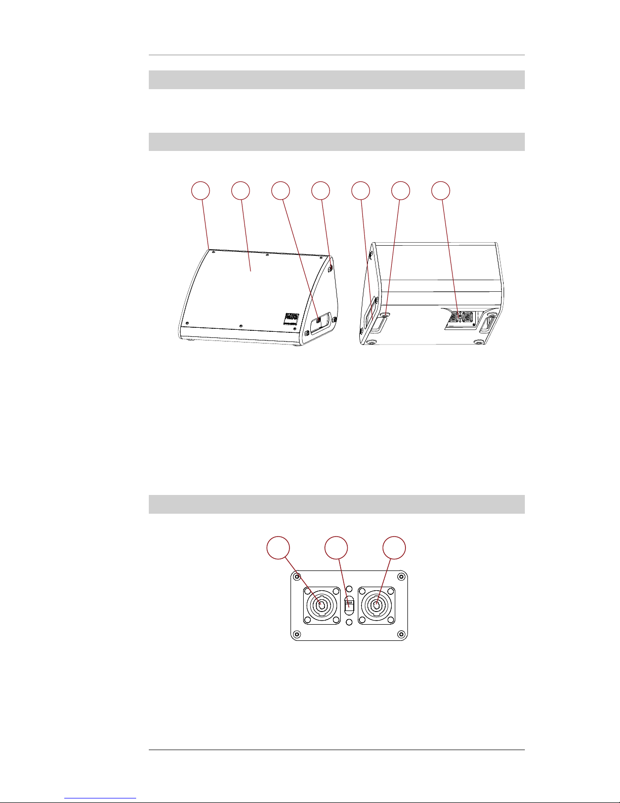
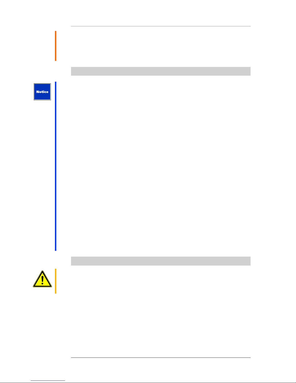
that nobody can trip over them. In addition to the main connector panel at the bottom, the
K&F SCENA 12 speaker provides extra SpeakOn ports on the side panels. Using those lateral
ports increases the risk of tripping.
!

User's Manual K&F SCENA 12
KLING & FREITAG GMBH © 2018 Version 1.2 Page 10 of 31
Unless this is impossible due to speaker placement or the general stage setting, be sure to
take appropriate measures including, for example, using cable bridges in order to avoid
tripping.
If necessary, use the main ports located at the bottom. In this case, too, be sure to avoid any
risk of tripping.
3.3 Protecting the Speakers, Reliability
Be sure to connect the K&F SCENA 12 speaker to a K&F SystemAmp, a K&F SystemRack, or a
linear power amp with up to 750 Wrms per channel (8 ohms) only.
Never feed audio at excessive levels to the speaker. Mixing consoles, equalizers, effect
units, etc. can produce clipping; excessive levels are normally visible on meters and through
indicators. Clipping at the power-amp output is typically shown by a red clipping indicator. In
any case, be sure to lower the signal level once it sounds distorted.
The built-in overload protection serves to protect the loudspeaker in case of high load
on the loudspeaker, such as feedback over a longer period of time. For this purpose, the
loudspeaker is completely separated from the signal. The interruption is cancelled after
about 10 seconds.
In no event, Kling & Freitag will warrant against any damages caused be excessive input levels
and cannot accept liability for any consequential damages.
Signals that may damage the speakers include the following:
• Continuous high-volume signals at high frequencies, continuous audio feedback
• Continuously distorted signals at high levels
• Sounds occurring when connecting, disconnecting, or switching on a device on the
audio system while the speaker is on
Never place your speakers
• where they are permanently exposed to direct sunlight,
• where they are exposed to high moisture,
• where they are exposed to strong vibrations or dust.
Damage Caused by the Speaker’s Magnetic Fields
Even when not connected, loudspeakers continuously produce a magnetic field. Therefore,
when transporting or placing the speaker, be sure to keep a minimum distance of about
1 meter between the speaker and magnetic disks or computer/video displays.
3.4 Preventing Hearing Damage
Caution
Keep your distance from operating speakers. This equipment is capable of delivering sound
pressure levels in excess of 90dB SPL, which may cause permanent hearing damage.

User's Manual K&F SCENA 12
KLING & FREITAG GMBH © 2018 Version 1.2 Page 11 of 31
4. Placement
The K&F SCENA 12 loudspeaker features two different foot types at the bottom and on the
right side panel.
The right-hand side features plastic sliding (1). These are mostly suitable for temporarily
putting the speaker down during transport. When operating the speaker in a vertical
position (i.e. placed on the sliding blocks), it may start moving due to vibration, so be sure to
secure it appropriately.
When using the speaker as a stage wedge, place it horizontally on the non-slipping rubber
feet at the bottom. These compensate vibrations in operation and will keep the speaker in its
position.
4.1 Using a Speaker Stand (Optional)
4.1.1 Safety Notes When Using a Stand
Warning
Place the stand securely on a level surface.
Stands require additional safeguard in the following and similar cases:
• The supporting surface does not allow for secure placement.
• The stability may be affected by the system height.
• Winds may occur.
• Persons may run into the system, causing it to fall down.
Suitable measures for securing stands include, for example:
• Weighting the stand shoes down
• Guying to stable objects
• Blocking access to the standing area
• Assigning security staff
Specific actions might become necessary to prevent threatening audience behavior.
Never place stands on emergency escape routes. Before placing speaker-stands on traffic
routes, make sure the path width is sufficient and all required blocking and marking actions
have been taken.
Remember that placing speakers onto or removing them from speaker-stands poses specific
risks. Be sure to use means suitable for the purpose (for example, platforms).
Warning
Before mounting, make sure the ground is level and will not give way to the speaker system
weight. Use only highly stable speaker stands designed for handling the weight of the K&F
SCENA 12 loudspeaker. Also keep in mind that many stands are not designed to withstand
lateral forces caused by gusts or bumps and might easily fall over. Similarly, the K&F SCENA
12 speaker-stand adapter is not designed for withstanding high lateral forces or shocks.

User's Manual K&F SCENA 12
KLING & FREITAG GMBH © 2018 Version 1.2 Page 12 of 31
4.1.2 Speaker-stand assembly
To mount the K&F SCENA 12 speaker-stand adapter:
1) Remove the 2 filler plugs from the
right side panel of the K&F SCENA
12 speaker.
2) Align the K&F SCENA 12 speaker-
stand adapter.
3) Tighten the K&F SCENA 12 speaker-
stand adapter using the M10 x 80
screws and the Locktix washers
supplied with the speaker stand
adapter.

User's Manual K&F SCENA 12
KLING & FREITAG GMBH © 2018 Version 1.2 Page 13 of 31
4) Check the K&F SCENA 12 speaker-
stand adapter for secure fit.
5) Place the caps onto the screw
heads.
6) Put the K&F SCENA 12 speaker onto
the speaker-stand.
7) Align the speaker.

User's Manual K&F SCENA 12
KLING & FREITAG GMBH © 2018 Version 1.2 Page 14 of 31
8) Check for a secure connection
and fasten the speaker using the
rotary knob on the K&F SCENA 12
speaker-stand adapter.
9) Speaker installation is now
complete, so you can safely wire
the speaker.

User's Manual K&F SCENA 12
KLING & FREITAG GMBH © 2018 Version 1.2 Page 15 of 31
5. Wiring
• Before connecting your K&F SCENA 12 speaker, switch off all devices and turn down all
faders and encoders.
• Be sure to use high-end speaker cables with an appropriate wire gauge. Select the wire
gauge with regard to the cable length.
• To connect the mixing console to the power-amp inputs, use shielded 2-pole balanced
microphone cables equipped with quality connectors.
• Avoid creating ground loops.
• Be sure to follow the pinouts shown in this manual.
• Check for correct polarity of the speaker links to the power amplifier. When using
amplifiers by different manufacturers, make sure the pinout is correct. If necessary,
consider modifying the amplifier or connector pinouts as required.
• Upon completing wiring, ensure that the connected speaker channels are working
in phase, for example, using a phase tester. When the connected channels are used
simultaneously, you can identify out-of-phase statuses by bass cancellation or mid-
frequency signals (e.g. voices) that cannot be located properly.
• When connecting multiple speakers, you can daisy-chain the signal from one speaker to
the next. Make sure that the total impedance of all speakers connected to an amplifier
does not fall below the minimum impedance specified for the amplifier. 1/R1 + 1/R2 + 1/
R3 + … = 1/Rtotal
6. Initial Operation
• Switch off all devices and turn down all volume controls on the mixing console and the
amplifiers.
• Wire your K&F SCENA 12 systems as described in this manual.
• Switch on the devices in the following order: first the mixing console, then the
controller and finally the power amplifiers! Be sure to observe this power-up sequence
at all times. Failing to do so may result in switch-on noise that may damage your
system.
• If you hear noise, turn off all devices in reverse order, then check all cable connections.
• Turn up all amplifier channels one after another and output a low-volume signal to the
system. Check whether the audio is properly routed to the appropriate speakers. Make
sure no noise is heard through those speakers.
• With amplifiers with insufficient input-stage headroom, you may not always be able
to prevent distortion by reducing the power-amp volume controls. In this case, the
clipping indicator may not light when clipping actually occurs! To prevent damage to
the speakers, we recommend fully turning up the power-amp volume controls, then
carefully turn up the volume on the mixing console or controller or reduce the limiter
threshold of the controller as appropriate in order not to overload the amplifiers.
• When turning off the system, first turn down the amplifier input controls. Next, power
down the amplifiers, then turn off the remaining devices.

User's Manual K&F SCENA 12
KLING & FREITAG GMBH © 2018 Version 1.2 Page 16 of 31
7. Setups and Connection Diagrams
The K&F SCENA 12 offers much flexibility in terms of cabling and operation.
You can connect a maximum of six speakers to a 4-wire NL4 cable fed by two amp channels.
For example, the first line could run from the amp to a main-terminal port. Further speakers
can be connected to either a main port or one of the lateral aux ports. The K&F SCENA 12
supports all reasonable connection types.
If you use a four-wire cable fed from two amp channels, you can select the output channel
individually on each K&F SCENA 12 speaker. You can connect up to three speakers per
channel.
If you don’t need to select a specific channel, you can also use a 2-wire NL4 cable.
In that case, be sure to set the channel selector to channel 1. Otherwise, you won’t hear
anything.
Connect the desired number of speakers (up to three channels per speaker, i.e. six in total)
and use the channel selector for setting the actual output channel.
a
b
•a: Playback of channel 1
•b: Playback of channel 2

User's Manual K&F SCENA 12
KLING & FREITAG GMBH © 2018 Version 1.2 Page 17 of 31
7.1 Sample configurations:
All wires of the following examples are 'Speakon NL4'.
Example 1:
122
1
Example 2:
1
2
2
2
1
1
Example 3:
11
22
1
2
Example 4:

User's Manual K&F SCENA 12
KLING & FREITAG GMBH © 2018 Version 1.2 Page 18 of 31
7.2 Connection
7.3 Available presets
There are four different presets for the K&F SCENA 12 speaker. They are divided into
'Monitor' and 'Top' and whether subwoofers are connected or not.
From the following table you can see for each application the intended preset.
If necessary, adjust the correct level balance with the output gain of the subwoofer on the
K&F systemamp or systemrack.
Overview LS-blocks:
Use as stage monitor Use as front loudspeaker/
top
without subwoofer SCENA 12 Monitor FR SCENA 12 Topteil FR
with subwoofer
(in standard-preset)
SCENA 12 Monitor LCut SCENA 12 Topteil LCut
with subwoofer,
(in 60 Hz Preset)
SCENA 12 Monitor FR SCENA 12 Topteil FR

User's Manual K&F SCENA 12
KLING & FREITAG GMBH © 2018 Version 1.2 Page 19 of 31
8. Dimensions
Weight: 18.4 kg

User's Manual K&F SCENA 12
KLING & FREITAG GMBH © 2018 Version 1.2 Page 20 of 31
9. Measuring Diagrams
9.1 Monitor with SystemAmp
Frequenzgang 'on axis'
FR mode
LCut mode
9.2 Monitor linear
Frequenzgang 'on axis'
Frequency response
Impedance
Frequenzgang 'on axis'
160
140
120
100
80
60
40
20
0
110
100
90
80
70
Table of contents
Other K&F Speakers manuals
Popular Speakers manuals by other brands

Denver
Denver BTG-615 instruction manual

Beta Three
Beta Three BS2002 user manual

KINGTA TECHNOLOGY
KINGTA TECHNOLOGY H2-6067V1S user manual

musikelectronic geithain
musikelectronic geithain TS30 Series Instructions for installation and use

Elipson
Elipson planet M quick guide

Steren
Steren BOC-1110BL user manual