Oilon ECO Inverter+ 7 Guide

M8003 2219EN
24 May 2022
INSTALLATION AND
COMMISSIONING
ECO Inverter+ 7-25


Contents
1 Introduction
1.1 Heat pumps covered in this manual...........................................................3
1.2 Instructions and diagrams...........................................................................3
1.3 Safety notice and warnings........................................................................ 3
1.4 Transportation and storage.........................................................................5
1.5 Scope of delivery........................................................................................ 6
1.6 Accessories................................................................................................. 8
2 Installation
2.1 Installation site.......................................................................................... 11
2.2 Dimensions, connections, and components............................................. 12
2.3 Outdoor temperature sensor.....................................................................14
2.4 In-line heater............................................................................................. 14
2.5 Change-over valve (optional)....................................................................16
2.6 DHW tank sensor......................................................................................17
2.7 Electrical connections, covers, and cable management...........................17
3 Heating circuits
3.1 Buffer tank.................................................................................................19
3.2 Buffer tank sensor.....................................................................................19
3.3 Flow temperature sensor for heating circuit 1.......................................... 20
3.4 Heating water temperature, return to condenser......................................22
3.5 Heating circuit’s control valve................................................................... 22
3.6 Heating circuit pump................................................................................. 25
3.7 Heating circuits 2 and 3............................................................................27
4 Commissioning
4.1 General......................................................................................................28
4.2 Signing in as a service level user............................................................ 28
4.3 Initial setup settings.................................................................................. 29
4.4 Design outdoor temperature..................................................................... 35
5 Operation
5.1 Heat pump operation................................................................................ 36
6 Technical data
6.1 Heat pump technical data.........................................................................38
6.2 Compressor units......................................................................................38
6.3 Performance data......................................................................................39
6.4 Technical data sheet (EN 14825)............................................................. 47
6.5 Operating conditions................................................................................. 48
6.6 Pumps and earth probe data....................................................................49
M8003 2219EN 1 (54)

1 Introduction
1.1 Heat pumps covered in this manual
Heat pump models
with EasyAce control
Designation Refrigerant
ECO Inverter+ 7–25 EasyAce 07 ECOINVERTER7-2507 R-410A
1.2 Instructions and diagrams
Document Designation
ECO Inverter+
Installation and commissioning
M8008 (34793615)
This manual
ECO Inverter+ 7-25
Electric diagram
34793613 (110894)
ECO Inverter+ 7-25
Piping diagram
34793614
EasyAce
Quick guide
M8007
(34793602)
EasyAce
Installation and initial setup
M8005
(34793601)
EasyAce
User manual
M8004
(34793603)
1.3 Safety notice and warnings
Read these instructions carefully before installation, commissioning, operation, or
maintenance of the device. The given instructions must be followed. Throughout this
manual, the following symbols are used to point out very important information:
Use special caution. The DANGER symbol indicates an immediate
hazard that will result in serious injury or death.
Use special caution. The WARNING symbol indicates a hazard that
may result in serious injury or death.
Use caution. The CAUTION symbol indicates a hazard that may result
in an injury.
M8003 2219EN 3 (54)

Pay attention. The NOTICE symbol indicates a risk of damage to the
equipment, components, or surroundings.
The ‘i’ (info) symbol indicates important information as well as useful
tips and hints.
Keep these instructions as well as the electrical diagrams available near the device.
Installation, commissioning, or service of the appliance is to be carried
out by authorized and trained personnel only, adhering to all local
regulations and requirements.
Wear proper personal protective equipment, such as protective
footwear, gloves, and safety goggles when necessary.
Electrical safety
Once powered on, some of the unit’s components carry a hazardous
voltage. Always pay attention to electrical safety when working with or
near electrical components.
Before any maintenance or servicing, switch off electricity using the
main switch and ensure that there is no voltage present in the unit’s
components.
Refrigerant
Refrigerant leaking from an open or broken circuit may cause
asphyxiation, severe frost damage, arrhythmia, or neurological
symptoms. If you suspect a refrigerant leak, leave the area immediately,
and seek fresh air. Help and warn others.
The unit includes a hermetically sealed refrigerant circuit filled with refrigerant R-410A.
Refrigerant R-410A is a mixture of two refrigerants: HFC-32 (R-32, difluoromethane)
and HFC-125 (R-125, pentafluoroethane).
Refrigerant R-410A is a fluorinated greenhouse gas and, consequently, subject to the
EU F-gas Regulation. Please recover the refrigerant as required by law, and transfer
the refrigerant for recycling or disposal as required by applicable laws, rules and
regulations.
The refrigerant is heavier than air. The refrigerant may accumulate in enclosed spaces,
especially at or below the floor level (for example, in basements). Ventilate the spaces
by opening the space’s doors and windows from the outside. Use fans, if necessary. Do
not enter any space where you suspect there to be leaked refrigerant present.
4 (54) M8003 2219EN

Safety devices
Do not bypass, disable, or damage any of the unit’s pressure switches
or other safeguards with tools, by accessing the system’s software, or
by any other means.
Bypassing the unit’s safeguards may lead to equipment failure, damage to property or
injury to people.
Lifting and handling
The weight of the unit presents a crush hazard. Use safe work methods
when lifting and handling the unit.
During lifting, do not walk or work under the heat pump or any other
suspended load.
Wireless touch screen
Use the wireless touch screen provided with the unit only for operating
the heat pump.
Using the touch screen for any other purpose may cause slowdowns or interference
in the use of the unit’s automation system, or prevent the system from being used
altogether.
Other considerations
To avoid slipping, keep floor surfaces dry, and seal off or report any
leaks that you detect.
1.4 Transportation and storage
Storage
Store the unit upright in a warm, dry place. Protect the device against water and dust.
Do not stack goods on the unit.
M8003 2219EN 5 (54)

Transportation
Transport the unit upright and protected against water and dust. Do not stack goods
on the unit. Use only safe lifting and handling methods when moving or lifting the
unit. After lifting, lower the unit carefully down onto the floor. Hard impacts can cause
equipment damage.
The compressor unit can be tilted up to 45 degrees from horizontal.
If the unit is tilted beyond 45 degrees, the compressor may not receive proper
lubrication at startup. As a result, the compressor may become damaged.
● If the unit has been accidentally tilted beyond 45 degrees, leave the unit in vertical
position for at least three hours before starting the compressor.
1.5 Scope of delivery
Equipment and components
Item PCS Oilon
designation
Wireless touch screen
● For using the EasyAce control
app to control the heat pump’s
automation system
1 378810400
Wireless touch screen ver. 1
Outdoor temperature sensor
● Sensor ID is TE0.
● Connect the sensor to the
cable TE0–W1.
1 36217543
Outdoor temperature sensor ver. 1
Condenser pump 1 34023129 Grundfos UPMXL GEO 25-125 180 PWM
Evaporator pump 1 34023075 Wilo-Stratos PARA 25/1-12 T16 180 mm 6h
Buffer tank temperature sensor 1
DHW storage tank temperature 1
Heating circuit 1 flow temperature
sensor
1
Connected to the heat pump’s control
cabinet, cable length approximately 4 m.
Torx T25 key
● Provided for opening the
device’s Torx T25 screws.
1 34798044
Torx T25 ver. 1
6 (54) M8003 2219EN

Sensors and actuators
EasyAce 7–25+
BRINE CIRCUIT
TE101 Brine circuit in (evaporator in) S
TE102 Brine circuit out (evaporator out) S
P101 Brine pump (evaporator circuit pump) S
HEATING
TE201 Heating water in (condenser in) S
TE202 Heating water flow (condenser out) S
P201 Heating pump (condenser circuit pump) S
EB203 In-line heater, condenser circuit O
TE255 Buffer tank temperature (tank upper section) S
TE266 Domestic hot water tank temperature (tank lower
section)
S
FV202 Change-over valve O
TE0 Outdoor temperature S
HEATING CIRCUIT 1*
TE212 Heating circuit 1 flow temperature S
P221 Heating circuit 1 pump O
FV222 Heating circuit 1 control valve O
TE213 Room temperature 1 OA**
HEATING CIRCUIT 2*
TE222 Heating circuit 2 flow temperature OA
P221 Heating circuit 2 pump OA
FV222 Heating circuit 2 control valve OA
TE223 Room temperature 2 OA
HEATING CIRCUIT 3
TE232 Heating circuit 3 flow temperature OA
P231 Heating circuit 3 pump OA
FV232 Heating circuit 3 control valve OA
TE233 Room temperature 3 OA
REFRIGERANT CIRCUIT
COMP1 Compressor S
TE2 Hot gas temperature S
PS1 Low pressure switch S
PS2 High pressure switch S
DATA HUB
HUB Connection device for the EasyAce system
(EasyAce Hub)
S
*If an auxiliary controller is not installed, one heating circuit can be regulated by a control valve, while the
second one does not have a control valve. The circuit controlled by the valve can be either heating circuit
1 or 2. Heating circuit 3 is always regulated by a control valve and requires an auxiliary controller.
**If the heating circuit does not have a control valve, the room temperature sensor can be installed without
auxiliary equipment.
S: Standard equipment
O: Optional accessory, can be connected to the heat pump’s automation system and enabled without
additional equipment.
OA: Optional equipment that requires an auxiliary controller kit (controller + enclosure) for installation.
M8003 2219EN 7 (54)

1.6 Accessories
For a full list of available accessories, please refer to brochures and price lists. Storage
tanks are presented in a separate storage tank brochure.
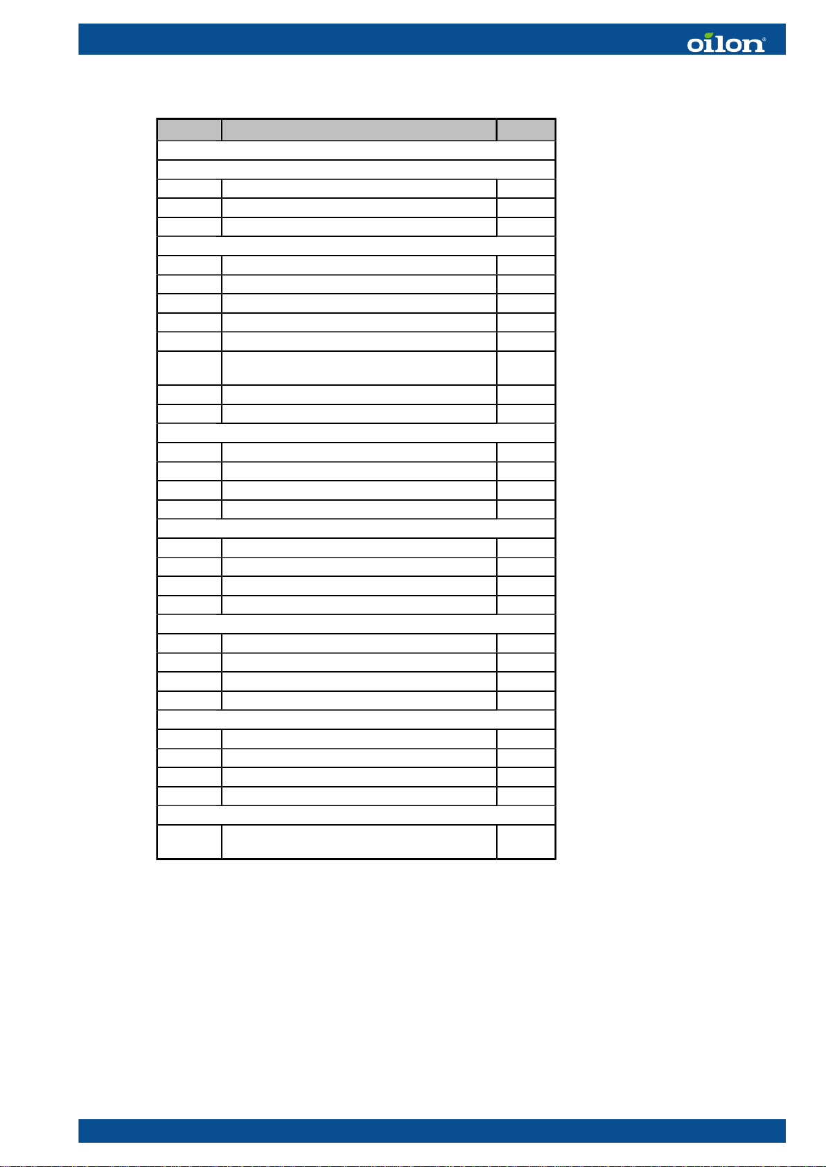
Accessories
Accessory Auxiliary controller with enclosure
Designation 32586192
Description An enclosure containing an auxiliary controller for regulating heating circuit 2 and
3 or increasing the number of I/O slots for different functions. Installed on top of
the heat pump unit. 24 V input from the heat pump, 230 V input from the building’s
distribution board.
Documents Electric diagram: 34793611 (110992), manual 34793612
Accessory Temperature sensor NTC10k 5 m
Designation 36217266
Description Sensor with flexible cable (length: 5 m), metallic probe (diameter: 6 mm, length: 50
mm), 1xNTC 10 kOhm, 2 wires, B(25/85)=3976, t0.97 s
Intended use Buffer tank temperature TE255
Heating circuit flow temperature TE212, TE222, TE232
Accessory Sensor pocket 6x200 G1/2
Designation 34021268
Description For 6 mm sensor probes, with cable gland, depth: 200 mm, G1/2" outer thread,
brass
Intended use Sensor pocket for buffer tanks and heating circuits
Compatible
equipment
36217266
Accessory Heating circuit control valve actuator, 3-point, 230 V
Designation 36962089
Description Esbe ARA651 12101200, 3-point SPDT, 230 V, 3 wires, 60 s 90°
Valve 34034065, 34034067, 34034068, 34034467
Accessory Heating circuit control valve actuator, 0–10 V 24 V
Designation 36962220
Description Esbe ARA639 12520100 (12520117 OEM), 0–10 V, 4–20 mA, 24 V AC/DC, 3 wires,
15/30/60/120 s 90°, pre-set to 60 s (DIP switch 2 ON), pre-set to OPEN (with
increasing signal) counterclockwise CCW (DIP switch 6 ON)
Valve 34034065, 34034067, 34034068, 34034467
Accessory 3-way control valve for heating circuit, DN 20-6.3
Designation 34034068
Description Esbe VRG131 11600900, DN20, Kvs 6.3, Rp 3/4"
Actuator 36962089, 36962220
8 (54) M8003 2219EN

Accessory 3-way control valve for heating circuit, DN25-10
Designation 34034065
Description Esbe VRG131 11601100, DN25, Kvs 10, Rp 1"
Actuator 36962089, 36962220
Accessory 3-way control valve for heating circuit, DN25-6.3
Designation 34034067
Description Esbe VRG131 11601100, DN25, Kvs 6.3, Rp 1"
Actuator 36962089, 36962220
Accessory 3-way control valve for heating circuit, DN20-4
Designation 34034467
Description Esbe VRG133 11602900, DN20, Kvs 4, 22 mm crimped connection
Actuator 36962089, 36962220
Accessory 3-way control valve for heating circuit, DN32-16
Designation 1154330
Description Esbe VRG131 11601200, DN32, Kvs 16, Rp 1 1/4"
Actuator 36962089, 36962220
Accessory 3-way control valve for heating circuit, DN40-25
Designation 1154332
Description Esbe VRG131 11603400, DN40, Kvs 25, Rp 1 1/2"
Actuator 36962089, 36962220
Accessory Change-over valve kit 1
Designation GEOEXCV1
Description Includes a change-over valve and valve actuator (designation: 34034063 and
34034064).
Accessory Change-over valve kit 2
Designation GEOEXCV2
Description Includes a change-over valve and valve actuator (designation: 34034205 and
34034204).
Accessory Change-over valve 1
Designation 34034063
Description LK 525 MultiZone 3V 0661109, 28 mm compression fitting, Kvs 8, B: space heating;
A: domestic hot water heating
Actuator 34034064
Accessory Change-over valve 2
Designation 34034205
Description Esbe 3F 40 11100400, DN 40, Kvs 44, flange connection
Actuator 34034204
M8003 2219EN 9 (54)

Accessory Change-over valve actuator
Designation 34034064
Description LK EMV 110-K 066062, SPST, 230 V, 3 m. Not energized: B (space heating);
energized: A (domestic hot water heating).
Valve 34034063
Accessory Change-over valve actuator
Designation 34034204
Description Esbe 90 series, 2-point 230 V AC, model 97, 12052500, running time 15 s
Valve 34034205
Accessory Thermostatic mixing valve assembly
Designation 34034069
Description Thermostatic mixing valve for domestic hot water LK 545-22 AquaMix 090195;
domestic cold water inlet, shut-off and non-return valve LK 508 AquaNode 22
090025; fill valve LK 536 ThermoFill EA EN 1717; safety valve LK 514 MultiSafe
090116 10 bar
Intended use Thermostatic mixing valve assembly with fill connection.
Accessory In-line heater, 6 kW
Designation 37069089
Description 3 x 2 kW (230 V L–N), connection box, thermostat 25–85 °C, overheat protection
110 °C (manual reset), 28 mm steel pipes
Intended use Electric in-line heater for installation in a heat pump’s condenser line. Option for
ECO Inverter+ heat pumps.
Accessory Heating circuit pump
Designation 34023128
Description Grundfos UPM3 AUTO 25–70 130 12h
Cable 34023128
Accessory Supply cable for Grundfos UMP3
Designation 1150078
Compatible
equipment
34023128
10 (54) M8003 2219EN

2 Installation
2.1 Installation site
Site planning and selection
● Install the unit and the associated equipment in a warm, dry place.
● The installation site’s ambient temperature must be within +5...+40 °C (non-
condensing).
● No condensate should accumulate onto the unit’s components from ambient air
(non-condensing atmosphere).
● The air at the installation site should be free of harmful quantities of dust or other
substances that may influence the heat pump’s performance, durability, or safety.
Unit base and leveling feet
Place the unit on a stable, steady base that can carry its entire weight. Mount the unit
securely in a vertical position onto its own leveling feet. Level the machine using the
machine’s leveling feet.
Maintenance and access clearance
The system must include shut-off valves that allow the unit to be isolated from the brine
circuit, heating circuit, and the domestic water system.
The unit should be easy to access for servicing from all sides. For ease of access:
● leave a sufficient clearance on all sides of the unit, or
● ensure that the heat pump or the compressor unit can be detached and moved to a
location that has enough space for servicing.
● Leave at least 80 cm of clearance in front of the unit.
● Leave at least 2 cm of clearance between the unit and any surrounding walls.
Access clearance ver. 1
Pos. Item
HP Heat pump
ACupboard, appliance, or
other object
M8003 2219EN 11 (54)

Floor drain
The unit’s installation site must have a floor drain. The site’s floor should be inclined so
that any runoff from the unit leads towards the drain.
2.2 Dimensions, connections, and components
Components, ECO Inverter+
ECO Inverter+ main patrs ver. 2
Pos. Item Description
Brine circuit side (evaporator) In from the top, out from the bottom.
Heating side (condenser) In from the bottom, out from the top.
WI Heating water in (condenser in) 1 1/4" outer thread
WO Heating water out (condenser out) 1 1/4" outer thread
BI brine circuit in (evaporator in) 1 1/4" outer thread
BO brine circuit out (evaporator out) 1 1/4" outer thread
AF Leveling feet M10, DIN/ISO 17/16 mm
TC Switchboard cover (Torx T25) The unit’s fuses and some of its terminal
blocks are located under this cover.
FC Compressor unit front panel (Torx T25) The unit’s switchboard is located behind this
cover.
HUB EasyAce data hub Behind a transparent panel (Torx T25)
12 (54) M8003 2219EN

Dimensions, ECO Inverter+
D077614revd ECO Inverter+ ver. 1
Heat pump L1 L2 L3 H1 H2 H3 H4 B1 B2
ECO Inverter+ 7–25 525 407 83 674 659 598 122 590 33
Heat pump BI/BO Ø WI/WO LF BF Ø DF
ECO Inverter+ 7–25 ISO 228/1-G1 1/4 B ISO228/1-G 1 1/4 B 425 522 35
M8003 2219EN 13 (54)

Fuses, ECO Inverter+
ECO Inverter+ 7–25Marking Function
Default Upon
delivery
F1 Compressor fuse ON ON
F2 In-line heater fuse N/A OFF
F3 Control fuse (automation system fuse) ON ON
F4 Condenser circuit pump and heating circuit 1 pump ON ON
F5 Evaporator circuit pump ON ON
2.3 Outdoor temperature sensor
The outdoor temperature sensor (TE0) is supplied already connected to its sensor
cable (TE0–W1). Install the sensor during the heat pump’s installation.
Extend the cable if necessary.
● Use a regular insulated copper twin cable for connecting the cable and extending
the cable.
● Select the cross-sectional area of the wires by consulting the table below.
● Join or splice the cable ends in a way that causes no additional electrical resistance
in the wires. Protect the joint against moisture and oxidation.
Cable length (m) 40 60 80 120
Wire cross-sectional area (mm2)0.50 0.75 1.0 1.5
Outdoor installation
Install the sensor outside the building with the sensor cable gland pointing downwards.
● Place the sensor in a position where the prevailing outdoor temperature can be
measured as accurately as possible.
● Make sure that the sensor is not exposed to solar radiation or heat from the
building.
Even though the sensor housing is protected against dust and water spray (IP65,
provided that the cable gland is pointed downwards), it is advisable to install the unit in
a location that is covered from rain. A good place for the sensor would be, for example,
under the eaves in a shady spot on the north wall of the building.
The type of the outdoor sensor is NTC 10 kΩ. The sensor’s β value is 3,435 K. Any
corresponding 10 kΩ NTC sensor can be used as an alternative. The sensor’s β value
can be changed from the unit’s automation settings.
2.4 In-line heater
An inline heater (label: EB203) can be installed in the heat pump’s condenser line.
14 (54) M8003 2219EN

Accessory In-line heater, 6 kW
Designation 37069089
Description 3 x 2 kW (230 V L–N), connection box, thermostat 25–85 °C, overheat protection
110 °C (manual reset), 28 mm steel pipes
Intended use Electric in-line heater for installation in a heat pump’s condenser line. Option for
ECO Inverter+ heat pumps.
Installation
Enable the heater from Initial setup settings (see chapter Commissioning).
The switchboards in ECO Inverter+ heat pumps have the electrical equipment
necessary for connecting an additional in-line heater (EB203), which is available as an
optional accessory.
1. Connect the heater to the switchboard as indicated in the unit’s electrical diagram.
2. Install the heater in the heating water flow line (from the condenser) as indicated in
the piping diagram.
3. Set the heater’s internal thermostat to its highest setting (85 °C).
4. Reset the heater’s overheat protection during installation.
The heater has either 28 mm stainless steel pipes or 1" threaded connections.
1. Before tightening any compression fittings, lubricate the inner surface of the ferrule.
2. Mount the fitting into position.
3. Tighten the fitting with your fingers until it is as tight as you can get it, then tighten
another 1/2 turns with a wrench.
General instructions
When an in-line heater has not been installed and enabled in the automation system,
the standard position for fuse F2 is OFF.
If an in-line heater has been installed and it needs to be disabled, disable the heater
from the heat pump’s settings. If an in-line heater has been installed and enabled in the
settings, do not set the heater’s fuse to the OFF position, unless there is a fault in the
heater.
In units that come with the in-line heater preinstalled, the heater’s internal
thermostat should not be adjusted. The thermostat has been set to its highest
setting (approximately 85 °C) at the factory. The thermostat will shut off power to the
immersion heater only if there is a malfunction in the heat pump’s automation system.
If you have accidentally turned the thermostat knob, turn the knob back to its highest
setting.
The in-line heater is equipped with an internal overheat protection device. The device
shuts the heater’s power off when the internal temperature of the immersion heater
cartridge exceeds 110 °C. To reset the switch, press the button on the black connection
box on top of the heater. The button is under a transparent plastic lid. Remove the
plastic lid with a slot-head screwdriver. Before resetting the overheat protection device,
determine what caused the device to trip and address the issue. The device may have
tripped due to vibration during transport or relocation.
M8003 2219EN 15 (54)

The electric immersion heater cartridge contains three 2-kW heating elements. The
combined power rating for the heating elements is 6 kW. The heating elements are
controlled in three stages. Stage 1 is connected to contactor K2. Its capacity is 2 kW.
Stage 2 is connected to contactor K3. Its capacity is 4 kW. When the third stage is
active, stages 1 and 2 are energized simultaneously.
In-line heater ver. 2
Pos. Item
1 Thermostat
2 Overheat protection reset
3 Power connection
In-line heater
2.5 Change-over valve (optional)
Accessory Change-over valve kit 1
Designation GEOEXCV1
Description Includes a change-over valve and valve actuator (designation: 34034063 and
34034064).
Accessory Change-over valve kit 2
Designation GEOEXCV2
Description Includes a change-over valve and valve actuator (designation: 34034205 and
34034204).
Install the change-over valve as indicated in the electric diagram and the piping
diagram. When the valve is not energized, the valve is in position B (for ‘building’),
which is used for space heating. When the valve is energized, the valve position is A
(for ‘aqua’), which is used for heating domestic hot water.
● Lubricate the inner surface of the ferrule before installation.
● Tighten the joint with your fingers until it is as tight as you can get it, then tighten
with a wrench.
● Tighten copper pipe joints 1/2 of a turn and steel pipe joints 1/2 of a turn. Use pipe
support sleeves in soft and half-hard copper pipes.
● Tighten plastic pipes using pipe support sleeves as indicated in the manufacturer’s
instructions. As a general rule, plastic pipes should be tightened 1 1/2 turns.
16 (54) M8003 2219EN

2.6 DHW tank sensor
The heat pump comes with the DHW storage tank temperature sensor (TE266) already
connected. The sensor cable is approximately 4.5 m long. The sensor probe’s diameter
is 6 mm and length 50 mm.
Install the sensor in the domestic hot water tank’s sensor pocket as specified in the
piping diagram.
● If a dedicated tank is used, install the sensor in the lower section of the tank.
● If a combined storage tank is used, install the sensor in the upper section of the
tank.
● Install the sensor probe (supplied with the unit) into a sensor pocket designed for
6 mm probes. The sensor pocket needs to extend into the interior of the tank by at
least 150 mm.
Install the sensor in a way that allows it to measure the temperature of the fluid in the
storage tank as accurately as possible. The sensor pocket needs to extend far enough
into the interior of the tank, and the sensor pocket’s internal diameter must be suitable
for the sensor probe’s diameter.
● Use only metallic sensor pockets that won't corrode to any significant degree (from
the outside or the inside) over time.
● The air gap between the probe and the pocket wall should be as small as possible.
If necessary, use thermal paste between the sensor probe and the pocket walls.
● To ensure that the sensor probe remains firmly seated at the bottom of the sensor
pocket, secure the sensor cable with a cable gland.
The cable can be extended if required. Use a regular insulated copper twin cable for
connecting the cable and extending the cable (0.5 mm2, length < 40 m).
● Join or splice the cable ends in a way that causes no additional electrical resistance
in the wires.
● Protect the joint against moisture and oxidation.
2.7 Electrical connections, covers, and cable management
Electrical connections
To access the unit’s switchboard, detach the cover on top of the compressor unit
(TC) and the compressor unit front panel (FC). Note that you can make most of the
connections by removing the top cover. Check the electrical connections from the unit’s
electric diagrams.
Switchboard cover and cable entries
Keep the switchboard cover (TC) closed and the screws fastened at all times. Remove
the cover (TC) only when performing electrical installation work.
Keep the cover closed and the screws fastened when filling or bleeding the system’s
circuits (brine circuit, heating circuit, or domestic water circuit). This will prevent leaking
water from entering the compressor unit and spilling over the switchboard. Water can
damage the switchboard.
M8003 2219EN 17 (54)

Thread the cables through the gland plate on the switchboard cover, ensuring that the
glands are properly sealed. Ensure that no leaks or condensate can travel along cables
or through or along insulation onto the switchboard behind the panel.
18 (54) M8003 2219EN
This manual suits for next models
1
Table of contents
Popular Inverter manuals by other brands

Galletti
Galletti MPI DC 10 Installation, use and maintenance manual

Steca
Steca StecaGrid 8 000+ 3ph Installation and operating instructions

GE
GE GEP3.5-1-10 user manual

ring
ring RSP500 manual

YASKAWA
YASKAWA varispeed G7 CIMR-G7B series instruction manual

Mecc Alte
Mecc Alte ECP3 Series Operating and maintenance instructions