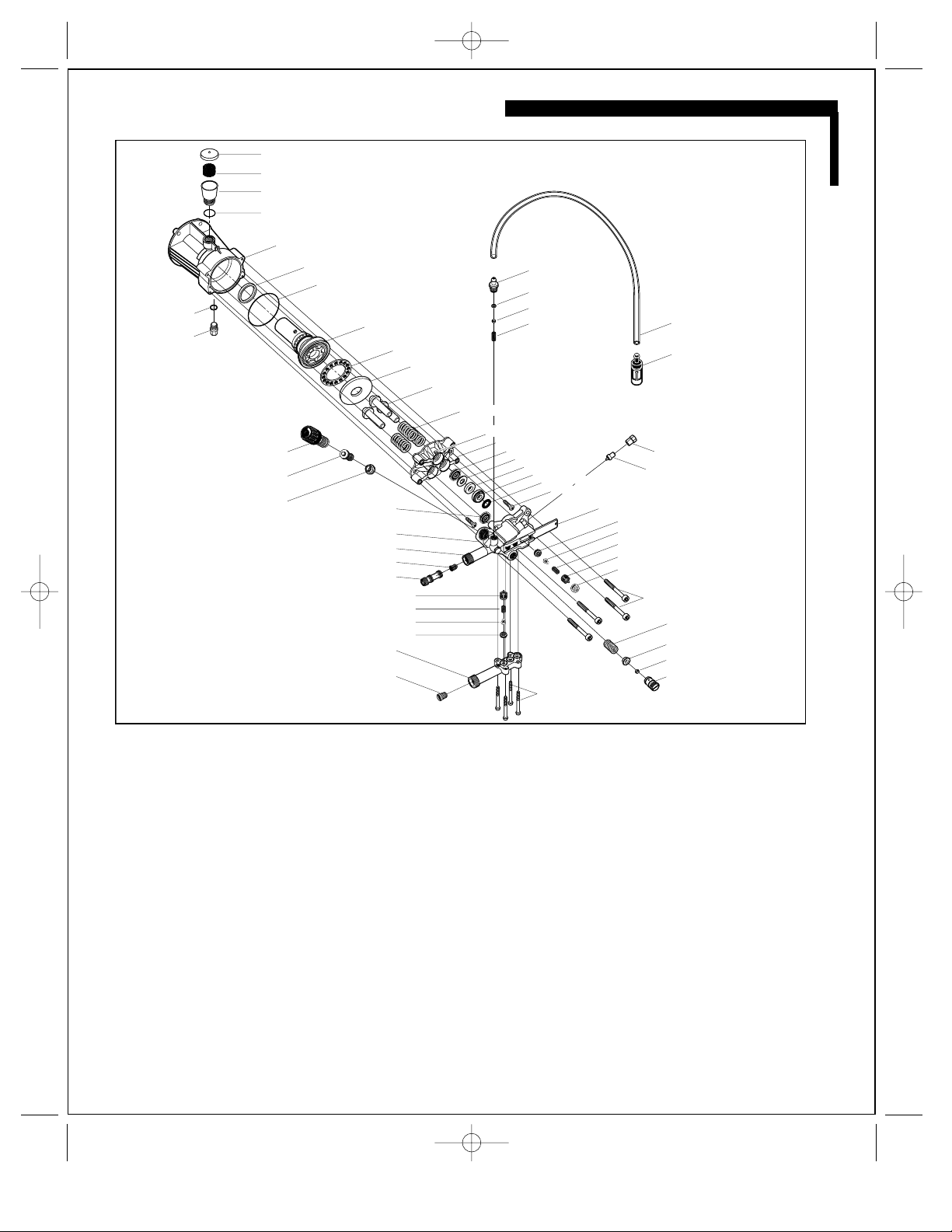
K&T 3.532-757.0 How to use

Service Handbook
High-Pressure
Washer Pump
3.532-785.0
10.00
Pump 785 9/28/01 3:06 PM Page 1
www.mymowerparts.com
For Karcher Pressure Washer Parts Call 606-678-9623 or 606-561-4983

Pump 785 9/28/01 3:06 PM Page 2
www.mymowerparts.com
For Karcher Pressure Washer Parts Call 606-678-9623 or 606-561-4983

TROUBLESHOOTING OVERVIEW
Tools Necessary to Service the
KARCHER®High-Pressure Washer Pump
Part 3.532-757.0
Special Tools
•Valve pliers . . . . . . . . . . . . . . . . . . . . . . . . . 4.901-062
•Installation tool . . . . . . . . . . . . . . . . . . . . . . 2.901-034
(HP seal, oil seal)
•Silicon grease . . . . . . . . . . . . . . . . . . . . . . . 6.288-044
(for packing and O-rings)
•Lithium grease . . . . . . . . . . . . . . . . . . . . . . 6.288-079
(for O-rings on bypass valve)
•Non-detergent pump oil . . . . . . . . . . . . . . . .6.288-050.0
Generic Tools
•Allen Wrench 8mm
•Allen Wrench 6mm
•Torx TX30 Socket Wrench
•Needle Nose Pliers
•Rubber Mallet
•Pliers
•Flat Head Screwdriver
•Phillips Head Screwdriver
•Hammer
•Safety Goggles
How to Use This Manual
It is not necessary to read this entire manual to find a solution
to a problem. This manual identifies four basic ways the pump may
malfunction. Find the section that defines the malfunction
of the pump. Turn to that section's overview page and identify
the specific problem. Then go to the solutions page for that
specific problem. If you don't know what the problem is, work your
way through the problems listed until you find and correct the
problem.
Low Water Pressure . . . . . . . . . . Section 1
Water Leaks . . . . . . . . . . . . . . . . . Section 2
Oil Leaks . . . . . . . . . . . . . . . . . . . Section 3
Detergent Delivery Failure . . . . . Section 4
Always wear safety rated eye protection and clothing.
For any other problems contact KARCHER®technical support
at 1-800-877-2424.
3
Pump 785 9/28/01 3:06 PM Page 3
www.mymowerparts.com
For Karcher Pressure Washer Parts Call 606-678-9623 or 606-561-4983

MASTER DIAGRAM
12...Swash
10...Swash assembly
9...Forward O ring
8...Pump shaft seal
7...Oil bath housing
4...O-ring
3...Oil reservoir
2...Oil filter
1...Oil reservoir vent cap
31...Detergent check valve
32...O-ring
33...Ball bearing
34...Spring
17...Pressure/volume control knob
18...Bypass valve
19...Bushing
30...Water inlet filter
25...Low pressure check valve basket (3)
56...Water outlet bolt (4)
13...Piston (3)
46...High pressure valve seat (3)
38...Thermal relief valve
20...High pressure seal (3)
6...Oil drain
plug
39...Low pressure oil seal (3)
40...Seal retaining ring (3)
41...Bushing seal (3)
42...Bushing (3)
45...High pressure valve slide
55...Safety relief valve
54...Ball bearing
53...Ball bearing seat
52...Spring
51...Pump head bolt (4)
50...High pressure valve cap (3)
37...Retainer nut
47...High pressure valve plate (3)
48...High pressure valve spring (3)
49...High pressure valve basket (3)
26...Low pressure check valve spring (3)
27...Low pressure check valve plate (3)
28...Low pressure check valve seat (3)
44...Piston guide retaining screw (2)
22...Water outlet
43...Scraper ring (3)
35...Detergent tube
36...Detergent filter
5...Oil drain
plug ring
11...Swash plate ball bearings
29...Water inlet
23...Non-return check valve
24...Nozzle insert
21...Pump head
14...Piston spring (3)
16...Piston housing
15...Weep holes (3)
Pump 785 9/28/01 3:06 PM Page 4
www.mymowerparts.com
For Karcher Pressure Washer Parts Call 606-678-9623 or 606-561-4983

KARCHER OVERVIEW
When the piston (13) is pushed forward by the swash assembly (10),
the low-pressure check valve (25-28) closes and water is conveyed
through the open high-pressure check valve (46-49) to the water
outlet (22). The pressure that is generated is dependent upon the flow
rate and the orifice diameter of the high-pressure nozzle.
Bypass Valve with Pressure Adjustment
When the trigger of the spray gun is pulled, the entire pump capacity
flows through the nozzle insert (24) to the water outlet (22). At this
time, the bypass valve (18) remains in the upper position and closes
off the path between the pressure chamber and the suction chamber.
When the trigger of the spray gun is released, water ceases to flow
through the nozzle insert (24). The non-return check valve (23) closes,
and the pressure in the high-pressure hose is maintained between the
trigger-actuated valve in the spray gun and the non-return check valve
(23). The pressure instantly rises in a surge, which causes the bypass
valve (18) to be pressed downwards. This opens the path between the
pressure chamber, located above the bypass valve (18), and the water
inlet housing (29). The pump continues to run only in bypass mode.
The safety relief valve (55) will open if the bypass valve (18) fails to
activate.
When the trigger of the spray gun is again pulled, the pressure in the
high-pressure hose drops suddenly. The spring inside the bypass valve
(18), together with the restricted pressure at the entrance to the
nozzle insert (24), pushes the bypass valve upwards. This causes the
circulation between the pressure chamber and the water inlet (29) to
close, and the pump builds up pressure once more.
This pump has a pressure/volume control (17) that enables you to
adjust the pressure and water flow at the pump. Other pumps have a
fixed pressure rating and are non adjustable. The pump shown in the
diagram is adjustable. This adjustment is made by turning the
pressure/volume control (17) downwards. This causes the bypass
valve (18) to be pushed open in a continuous movement. A part of the
pump’s capacity then flows from the pressure chamber into the water
inlet housing (29) and the operating pressure drops to the amount that
has been set by turning the pressure/volume control (17).
Thermal Protection Device
If the pump should continue to run in the bypass mode for an
extended amount of time (max 5 min.), the water circulating within the
pump will reach a temperature level that will cause internal damage.
This is prevented by the thermal relief valve (38). The thermal relief
valve will release the hot water and then automatically reset itself.
Detergent Delivery System
In this system there is a nozzle insert (24) in the water outlet (22). The
entire pump capacity flows through the nozzle insert to the spray gun.
Detergent can only be drawn in by the nozzle insert (24) if the nozzle
of the spray wand has been set to low pressure. This causes the pump
pressure to fall to approximately 435 PSI (low pressure), and the
greatest degree of negative pressure (11.6 PSI) is generated at the
lateral hole in the nozzle insert so that detergent can be drawn into
the unit via the detergent suction tube (35) and detergent filter (36).
If the spray nozzle on the spray wand is set for high-pressure
operation, the hole in the nozzle insert (24) does not create any
Swash Plate Assembly
The three pistons (13) are driven by the swash plate assembly (10),
which is mounted to the engine shaft. In the case of a vertically
configured machine, a drive bolt is screwed into the engine shaft and
then inserted into the pump shaft. As soon as the engine shaft rotates,
the swash assembly (10) rotates as well. This causes the pistons (13)
to move backwards and forwards. The piston stroke depends upon the
angle of the swash assembly (10). The greater the angle of the swash
plate, the longer the piston stroke. One revolution of the swash plate
gives the pistons one suction stroke and one pressure stroke.
Oil Bath
The swash plate assembly and pistons are bathed in oil (oil type
15W40 non-detergent). The oil level should be just above the high side
of the swash plate (12). It is important that the machine is on level
ground when checking the oil level.
In order to drain the oil, the drain plug (6), located beneath the oil bath
housing (7) will have to be removed. To add oil, remove the vent cap
(1) from the oil reservoir (3) and add to the required level.
Note: Some pumps do not have a drain plug, or oil reservoir. In order
to add oil in this case, the pump head (21) and piston housing (16) will
have to be removed.
Pistons With Seals
The three pistons (13) are pressed against the swash plate (12) of the
swash plate assembly (10) by powerful springs (14). These three
pistons are manufactured from tempered, surface-hardened steel and
are non-corrosive with regards to detergents and rust.
The pump delivery capacity is determined by
- the rotational speed of the motor
- the diameter of the pistons
- the length of the piston stroke.
The pistons (13) in industrial units are fitted with a high-pressure seal
(20) and a low-pressure seal (39). Non-industrial units have only a
high-pressure seal (20).
The three pistons each have an oil seal (39) mounted in the piston
housing (16). These three oil seals, along with the shaft seal (8), retain
the oil in the oil bath housing. The weep holes (15) are in the piston
housing (16) and allow water or oil to drip out into the open.
A water leakage rate of one drop per piston per minute is allowable
during high-pressure operation. If oil is leaking from the weep holes
(15), there is either a leak in the oil seals or there is piston damage.
Low-Pressure and
High-Pressure Check Valves
Each piston works with one low-pressure check valve (25-28) and one
high-pressure check valve (46-49). Each of these check valves is
constructed of the same basic components: the valve cage, spring,
valve plate with guide shaft and the valve seat with O-ring.
The sealing surface between the valve plate (27 & 47) and the valve
seat (28 & 46) is conical. The valve plate and valve seat are
manufactured from either plastic or stainless steel depending upon the
particular unit involved.
When the piston (13) is forced backwards by the spring (14) in the oil
bath housing (7), the high-pressure check valve (46-49) closes and
water is drawn in through the supply line / suction chamber at the
water inlet (29), through the inlet filter (30), and through the open low-
pressure check valve (25-28).
5
Pump 785 9/28/01 3:06 PM Page 5
www.mymowerparts.com
For Karcher Pressure Washer Parts Call 606-678-9623 or 606-561-4983

negative pressure, and no detergent can be drawn into the unit.
The detergent check valve consists of a small spring (31) with a ball,
O-ring and nipple. When operating in the detergent mode, the negative
pressure created by the nozzle insert causes the ball to be drawn
away from the O-ring, against the tension of the spring. Detergent can
then be drawn into the unit.
When operating in the high-pressure mode, the ball seals off the
detergent connection so that no water can flow into the container of
detergent.
6
KARCHER OVERVIEW
PART NUMBERS
High Pressure Washer Pump 3.532-785.0
ITEM #(S)
DESCRIPTION PART # QTY. IN
PUMP
1 Oil reservoir cap 5.063-651.0 1
2 Oil filter 5.132-107.0 1
3 Oil reservoir 5.070-194.0 1
4 O-ring 6.362-168.0 1
5 Oil drain plug ring 7.362-003.0 1
6 Oil drain plug 7.382-085.0 1
7 Oil bath housing 5.093-207.0 1
8 Pump shaft seal 7.387-018.0 1
9 Forward o-ring 6.363-067.0 1
10 Swash plate assembly with 5.120-326.0 1
Cylinder bearing 7.401-027.0 1
Coupling element 4.120-192.0 1
Spring 7.318-002.0 1
11 Swash plate ball bearings 6.401-185.0 1
12 Swash plate 5.120-326.0 1
13 Piston 5.553-434.0 3
14 Piston spring 6.332-427.0 3
15 Piston housing 5.060-677.0 1
16 Pressure/volume control knob with 5.321-307.0 1
Spindle 4.401-079.0
17 Bypass valve (multiple numbers)
top o-ring set 6.362-454.0 1
piston 5.553-383.0 1
spring 5.332-425.0 1
valve seat 5.581-242.0 1
valve seat o-ring 6.362-169.0 1
threaded spindle 5.305-274.0 1
18 Bushing 5.110-630.0 1
19 High-pressure seal 6.365-432.0 3
20 Pump head 5.550-266.0 1
21 Water outlet 5.063-897.0 1
22 Non-return check valve 5.584-091.0 1
23 Nozzle insert 5.769-138.0 1
24, 25 Low-pressure check valve basket, 4.580-371.0 3
26, 27 spring, plate and seat
ITEM #(S)
DESCRIPTION PART # QTY. IN
PUMP
28 Water inlet housing 5.063-897.0 1
29 Water inlet filter 6.414-252.0 1
30 Detergent check valve 5.443-448.0 1
31 O-ring 6.362-175.0 1
32 Ball-bearing 7.401-909.0 1
33 Spring 5.332-258.0 1
34 Detergent tube 6.388-216.0 1
35 Detergent filter 4.862-032.0 1
36 Retainer nut 5.411-150.0 1
37 Thermal relief valve 5.413-067.0 1
38 Low pressure oil seal 6.365-340.0 3
39 Seal retaining ring 5.115-465.0 3
40 Bushing seal 6.365-434.0 3
41 Bushing 5.112-576.0 3
42 Scraper ring 5.115-744.0 3
43 Piston guide retaining screw 7.303-047.0 2
44 High pressure valve slide 5.003-983.0 1
45,46 High-pressure valve cage, spring, 4.580-371.0 3
47,48 plate and seat
50 Pump head bolts 7.306-047.0 4
51 Spring 5.332-446.0 1
52 Ball-bearing seat 5.411-070.0 1
53 Ball-bearing 7.401-909.0 1
54 Safety relief valve 5.583-164.0 1
55 Water outlet bolt 7.306-105.0 4
NOT PICTURED IN DIAGRAM
Garden hose connection 9.154-009.0 1
Piston spring retaining clip 7.343-478.0 3
Pump 785 9/28/01 3:06 PM Page 6
www.mymowerparts.com
For Karcher Pressure Washer Parts Call 606-678-9623 or 606-561-4983

SECTION 1 / LOW WATER PRESSURE
7
Problems That Cause Low Water Pressure
A. Water Supply
A problem with the water supply. Use cold water only.
B. Worn Nozzle
A worn nozzle on the spray wand.
C. Water Inlet Filter
A clogged water inlet filter (30).
D. Bypass Valve
Worn O-rings on the bypass valve (18) or the bypass valve is hanging up.
E. Safety Relief Valve
The safety relief valve (55) opens if the bypass valve (18) is not working.
Low water pressure can result if the valve (55) does not seal or does not reseat.
F. Low-Pressure Check Valve
Low-pressure check valve (26-28) fails to function properly.
G. High-Pressure Check Valve
High-pressure check valve (46-49) fails to function properly.
H. Water Leaks – See Section 2 / Water Leaks
Water leaks.
I. Pump is Cycling – See Section 4 / Detergent Delivery Failure
Non-return check valve (23) or Nozzle insert (24) is damaged and must be replaced.
12...Swash
10...Swash assembly
9...Forward O ring
8...Pump shaft seal
7...Oil bath housing
4...O-ring
3...Oil reservoir
2...Oil filter
1...Oil reservoir vent cap
31...Detergent check valve
32...O-ring
33...Ball bearing
34...Spring
17...Pressure/volume control knob
18...Bypass valve
19...Bushing
30...Water inlet filter
25...Low pressure check valve basket (3)
56...Water outlet bolt (4)
13...Piston (3)
46...High pressure valve seat (3)
38...Thermal relief valve
20...High pressure seal (3)
6...Oil drain
plug
39...Low pressure oil seal (3)
40...Seal retaining ring (3)
41...Bushing seal (3)
42...Bushing (3)
45...High pressure valve slide
55...Safety relief valve
54...Ball bearing
53...Ball bearing seat
52...Spring
51...Pump head bolt (4)
50...High pressure valve cap (3)
37...Retainer nut
47...High pressure valve plate (3)
48...High pressure valve spring (3)
49...High pressure valve basket (3)
26...Low pressure check valve spring (3)
27...Low pressure check valve plate (3)
28...Low pressure check valve seat (3)
44...Piston guide retaining screw (2)
22...Water outlet
43...Scraper ring (3)
35...Detergent tube
36...Detergent filter
5...Oil drain
plug ring
11...Swash plate ball bearings
29...Water inlet
23...Non-return check valve
24...Nozzle insert
21...Pump head
14...Piston spring (3)
16...Piston housing
15...Weep holes (3)
Pump 785 9/28/01 3:06 PM Page 7
www.mymowerparts.com
For Karcher Pressure Washer Parts Call 606-678-9623 or 606-561-4983

A. Water Supply
1. Check faucet. 4.0 gpm is required.
2. Outside diameter of hose should be 3/4”.
3. Maximum length of hose should be 50’.
4. The inlet water pressure should not exceed 90 psi.
5. Hose should not be kinked or damaged.
B. Nozzle
1. Check function and setting of original nozzle by using an in-house
nozzle. If pump functions properly with in-house nozzle but
malfunctions with original nozzle, replace nozzle.
C. Water Inlet Filter
1. Remove filter with pair of valve pliers. (figure 1)
2. Clean filter.
3. Replace filter if it is torn, bent or missing.
4. Reinstall filter.
Note: If water inlet filter is missing or damaged, further damage
may have occurred inside the pump.
D. Bypass Valve
1. Unscrew pressure volume control assembly. (figure 2)
2. Remove brass bushing. (figure 3)
Note that bushing is positioned with large side down.
3. Pull out bypass valve. (inset figure 3)
4. Inspect bypass valve for damage and lubrication.
Inadequate lubrication will cause valve to hang up.
5. Inspect O-rings for nicks or cuts. Replace if necessary.
6. Grease only large O-rings with lithium grease. (figure 4)
7. Replace bypass valve if necessary.
E. Safety Relief Valve
1. Unscrew the safety relief valve screw cap. (figure 5)
2. Remove spring, valve seat and ball. (inset figure 5)
3. Check for wear or pitting.
4. Replace valve if necessary.
5. If valve seat in the cylinder head is defective, the entire
safety relief valve must be replaced.
6. Reassemble and replace screw cap making sure ball is in seat.
Note: Pitting will occur if inlet filter is damaged or missing.
8
SECTION 1 / LOW WATER PRESSURE SOLUTIONS
A. Water Supply
B. Nozzle
C. Water Inlet Filter
D. Bypass Valve
E. Safety Relief Valve
figure 5
figure 1
figure 4
figure 2
figure 3
Large O-ring
Small O-ring
Pump 785 9/28/01 3:06 PM Page 8
www.mymowerparts.com
For Karcher Pressure Washer Parts Call 606-678-9623 or 606-561-4983

SECTION 1 / WATER PRESSURE SOLUTIONS
2. Remove 3 plastic valve caps.
3. Check the valve for wear, debris and pitting. Replace if necessary.
4. Grease O-rings lightly with
silicone grease and reassemble.
(figure 10)
H. Water Leaks – See Section 2 / Water Leaks
I. Pump is Cycling –
See Section 4 / Detergent Delivery Failure
F. Low-pressure Check Valve
1. Remove water inlet housing with torx TX30 bit (5 bolts). (figure 6)
2. Remove low-pressure check valve, including valve disk and spring,
with special valve pliers. (figure 7)
3. Check the valve for wear, debris and pitting.
Note: If any one low-pressure valve is damaged, all three valves
should be replaced.
4. Lightly grease O-rings with silicone grease.
5. Reassemble and reinstall.
Note: Low-pressure check valves must be ordered as a unit.
Individual check valve parts cannot be ordered separately.
G. High-pressure Check Valve
1. Remove valve plate in tapping plate with screw driver.
9
F. Low-Pressure Check Valve
G. High-Pressure Check Valve
H. Water Leaks
I. Pump Cycling
figure 7
figure 10
figure 6
O-ring
O-ring
figure 8
figure 9
Pump 785 9/28/01 3:06 PM Page 9
www.mymowerparts.com
For Karcher Pressure Washer Parts Call 606-678-9623 or 606-561-4983

10
Problems That Cause Water Leaks
A. Thermal Relief Valve
The thermal relief valve (38) protects the pump from hot water temperatures in bypass mode.
If the thermal relief valve is damaged or does not reset, there will be a continual leak.
Check thermal relief valve (38).
Note:
It is normal for the thermal relief valve to release hot water, if the pump continues to run in the
bypass mode for an extended amount of time, which causes the water circulating within the
pump to reach a temperature level that will cause internal damage. Once the valve releases
the hot water, it will automatically reset itself.
B. weep holes – High-Pressure Seals
Water leaking from the weep holes (15) can indicate a leak in the high-pressure seals.
Check seals for damage.
C. weep holes – Low-Pressure Seals
Water leaking from the weep holes (15) can indicate a leak in the low-pressure seals (39).
Check the seals for damage.
12...Swash
10...Swash assembly
9...Forward O ring
8...Pump shaft seal
7...Oil bath housing
4...O-ring
3...Oil reservoir
2...Oil filter
1...Oil reservoir vent cap
31...Detergent check valve
32...O-ring
33...Ball bearing
34...Spring
17...Pressure/volume control knob
18...Bypass valve
19...Bushing
30...Water inlet filter
25...Low pressure check valve basket (3)
56...Water outlet bolt (4)
13...Piston (3)
46...High pressure valve seat (3)
38...Thermal relief valve
20...High pressure seal (3)
6...Oil drain
plug
39...Low pressure oil seal (3)
40...Seal retaining ring (3)
41...Bushing seal (3)
42...Bushing (3)
45...High pressure valve slide
55...Safety relief valve
54...Ball bearing
53...Ball bearing seat
52...Spring
51...Pump head bolt (4)
50...High pressure valve cap (3)
37...Retainer nut
47...High pressure valve plate (3)
48...High pressure valve spring (3)
49...High pressure valve basket (3)
26...Low pressure check valve spring (3)
27...Low pressure check valve plate (3)
28...Low pressure check valve seat (3)
44...Piston guide retaining screw (2)
22...Water outlet
43...Scraper ring (3)
35...Detergent tube
36...Detergent filter
5...Oil drain
plug ring
11...Swash plate ball bearings
29...Water inlet
23...Non-return check valve
24...Nozzle insert
21...Pump head
14...Piston spring (3)
16...Piston housing
15...Weep holes (3)
SECTION 2 / WATER LEAKS
Pump 785 9/28/01 3:06 PM Page 10
www.mymowerparts.com
For Karcher Pressure Washer Parts Call 606-678-9623 or 606-561-4983

SECTION 2 / WATER LEAK SOLUTIONS
• Place seal, flat side down, on installation tool.
• Fill groove with silicone grease.
(figure 14)
• Place brass sleeve in
pump head.
• Put installation tool into sleeve and press until seal pops
into place. (figure 15)
• Remove tool and then remove sleeve.
(inset figure 15)
A. Thermal Relief Valve
1. Remove thermal relief valve screw cap. (figure 11)
2. Disassemble thermal relief valve.
(inset figure11)
3. Inspect and replace with new valve if necessary.
B. weep holes - High-Pressure Seals
1. Remove 4 pump head bolts using 6mm allen wrench. (figure 12)
2. Remove pump head.
3. Carefully remove the 3 high-pressure seals. (figure 13)
4. Check seals and pistons for wear and tear and replace if necessary.
See Section 3 / Oil Leaks, D. weep holes for piston replacement.
5. Replace all three seals using installation tool.
11
A. Thermal Relief Valve
B. weep holes – High-Pressure Seals
C. weep holes – Low-Pressure Seals
figure 12
figure 13
figure 14
figure 11
figure 15
Brass Sleeve
Pump 785 9/28/01 3:06 PM Page 11
www.mymowerparts.com
For Karcher Pressure Washer Parts Call 606-678-9623 or 606-561-4983

C. weep holes - Low-Pressure Seals
1. Remove low-pressure bushing from piston.
(figure 17)
2. Remove washer from bushing.
(figure 17)
3. Remove low pressure seal.
(figure 18)
4. Inspect scraper ring. Replace if damaged.
5. Inspect O-ring on bushing.
6. Apply silicone grease to seal
7. Place bushing back on piston.
Circulation holes must line up with weep holes.
(figure 19)
12
SECTION 2 / WATER LEAK SOLUTIONS
C. weep holes – Low Pressure Seals
figure 17
figure 18
figure 19
Scraper Ring
Washer
Bushing
Seal
Circulation
Holes
Pump 785 9/28/01 3:06 PM Page 12
www.mymowerparts.com
For Karcher Pressure Washer Parts Call 606-678-9623 or 606-561-4983

SECTION 3 / OIL LEAKS
13
Problems That Cause Oil Leaks
A. Drain Plug
A loose drain plug (6) or damaged drain plug ring (5).
B. Oil Reservoir
A damaged oil reservoir (3), missing oil reservoir filter (2), or damaged O-ring (4).
If the oil bath housing (7) is overfilled, oil will leak from vent cap (1).
C. Weep holes
If oil is leaking from the weep holes (15), there is either a leak in the low-pressure
seals (39) or the high-pressure seals (20); or there is piston (13) damage.
D. Pump Shaft Seal
A damaged or worn pump shaft seal (8).
12...Swash
10...Swash assembly
9...Forward O ring
8...Pump shaft seal
7...Oil bath housing
4...O-ring
3...Oil reservoir
2...Oil filter
1...Oil reservoir vent cap
31...Detergent check valve
32...O-ring
33...Ball bearing
34...Spring
17...Pressure/volume control knob
18...Bypass valve
19...Bushing
30...Water inlet filter
25...Low pressure check valve basket (3)
56...Water outlet bolt (4)
13...Piston (3)
46...High pressure valve seat (3)
38...Thermal relief valve
20...High pressure seal (3)
6...Oil drain
plug
39...Low pressure oil seal (3)
40...Seal retaining ring (3)
41...Bushing seal (3)
42...Bushing (3)
45...High pressure valve slide
55...Safety relief valve
54...Ball bearing
53...Ball bearing seat
52...Spring
51...Pump head bolt (4)
50...High pressure valve cap (3)
37...Retainer nut
47...High pressure valve plate (3)
48...High pressure valve spring (3)
49...High pressure valve basket (3)
26...Low pressure check valve spring (3)
27...Low pressure check valve plate (3)
28...Low pressure check valve seat (3)
44...Piston guide retaining screw (2)
22...Water outlet
43...Scraper ring (3)
35...Detergent tube
36...Detergent filter
5...Oil drain
plug ring
11...Swash plate ball bearings
29...Water inlet
23...Non-return check valve
24...Nozzle insert
21...Pump head
14...Piston spring (3)
16...Piston housing
15...Weep holes (3)
Pump 785 9/28/01 3:06 PM Page 13
www.mymowerparts.com
For Karcher Pressure Washer Parts Call 606-678-9623 or 606-561-4983

A. Drain Plug (figure 20)
1. Check drain plug. Tighten or replace if necessary.
2. Inspect drain plug seal. Replace if necessary.
3. Reassemble and reinstall the drain plug.
B. Oil Reservoir (Figure 21)
1. If oil is spurting from oil reservoir vent cap, the oil level is too high.
Drain to specified level. (See note in Section 2.)
2. Inspect oil reservoir, seal and filter for damage.
3. Replace if necessary.
4. Check that vent nipple is cut.
5. Check O-ring under oil reservoir. If pitted or deformed, replace.
C. weep holes – Oil Seals
1. Unscrew the oil drainage plug and drain the oil into
a suitable container.
2. Remove piston housing.
(figure 22)
• Remove four pump head bolts
with an allen wrench and remove the pump head.
(See Section 2, figure 12)
• Re-install two of the pump head bolts with a 1/2” shim
composed of washers or a metal sleeve about 3/8”
in diameter into two diagonally opposing weep holes of
piston guide housing.
(figure 22)
• Remove the two piston guide retaining screws.
• Back off the housing by loosening up on the two pump
head bolts until spring tension in the piston guide housing
is relieved.
(inset figure 22)
• Alternate between nuts after every few turns
to keep housing level.
• Remove the two pump head bolts and shim when spring
tension is relieved.
14
SECTION 3 / OIL LEAK SOLUTIONS
A. Drain Plug
B. Oil Reservoir
C. weep holes / Oil Seals
figure 20 figure 22
Drain Plug
Seal
Drain Plug
figure 21
Oil Vent Cap
Oil Vent
Nipple
Piston
Housing
Retaining
Screws
O-ring
Pump 785 9/28/01 3:06 PM Page 14
www.mymowerparts.com
For Karcher Pressure Washer Parts Call 606-678-9623 or 606-561-4983

SECTION 3 / OIL LEAK SOLUTIONS
• Soak new oil seals in water
for 10 minutes. (inset figure 25)
• Make sure housing is clean and dry.
• Place oil seal into recessed end of installation tool.
Sleeve is not used. Groove in seal should face oil.
• Place seal in housing using installation tool.
(figure 25)
• Do not grease groove in oil seal.
• Push until seal hits bottom.
D. Pump Shaft Seal
1. Remove swash plate assembly.
(figure 26)
2. If oil seal on shaft is worn out call 1-800-KARCHER.
3. To remove oil seal, push shaft through swash plate.
3. Pull out piston guide assembly.
(figure 23)
4. Inspect forward O-ring and seal. Replace if necessary.
5. Remove and inspect pistons for wear or scoring.
Replace if necessary.
7. Remove the 3 oil seals with flat head screwdriver.
(figure 24)
8. Inspect and replace oil seals if necessary.
15
D. weep holes / Oil Seals
E. Pump Shaft Seal
figure 26
figure 25
figure 23
Forward O-ring
figure 24
Forward O-ring
Pump 785 9/28/01 3:06 PM Page 15
www.mymowerparts.com
For Karcher Pressure Washer Parts Call 606-678-9623 or 606-561-4983

16
Detergent Delivery Failure
A. Pump Not Drawing Detergent or Water Exiting Detergent Tube
Detergent filter (36) or Detergent non-return check valve (31) may be clogged or damaged.
Nozzle insert (24) may be worn.
Nozzle of the spray wand has been set to high pressure
B. Pump Is Cycling
Non-return check valve (23) or Nozzle insert (24) is damaged and must be replaced.
12...Swash
10...Swash assembly
9...Forward O ring
8...Pump shaft seal
7...Oil bath housing
4...O-ring
3...Oil reservoir
2...Oil filter
1...Oil reservoir vent cap
31...Detergent check valve
32...O-ring
33...Ball bearing
34...Spring
17...Pressure/volume control knob
18...Bypass valve
19...Bushing
30...Water inlet filter
25...Low pressure check valve basket (3)
56...Water outlet bolt (4)
13...Piston (3)
46...High pressure valve seat (3)
38...Thermal relief valve
20...High pressure seal (3)
6...Oil drain
plug
39...Low pressure oil seal (3)
40...Seal retaining ring (3)
41...Bushing seal (3)
42...Bushing (3)
45...High pressure valve slide
55...Safety relief valve
54...Ball bearing
53...Ball bearing seat
52...Spring
51...Pump head bolt (4)
50...High pressure valve cap (3)
37...Retainer nut
47...High pressure valve plate (3)
48...High pressure valve spring (3)
49...High pressure valve basket (3)
26...Low pressure check valve spring (3)
27...Low pressure check valve plate (3)
28...Low pressure check valve seat (3)
44...Piston guide retaining screw (2)
22...Water outlet
43...Scraper ring (3)
35...Detergent tube
36...Detergent filter
5...Oil drain
plug ring
11...Swash plate ball bearings
29...Water inlet
23...Non-return check valve
24...Nozzle insert
21...Pump head
14...Piston spring (3)
16...Piston housing
15...Weep holes (3)
SECTION 4 / DETERGENT DELIVERY FAILURE
Pump 785 9/28/01 3:06 PM Page 16
www.mymowerparts.com
For Karcher Pressure Washer Parts Call 606-678-9623 or 606-561-4983

SECTION 4 / DETERGENT DELIVERY FAILURE SOLUTIONS
5. Remove tube from nipple
• Remove detergent non-return check valve.
(figure 29)
• Inspect non-return check valve for clogs.
Note: Leaving detergent in pump will cause ball to stick.
6. Reinstall non-return check valve, nipple, metering knob and hose.
B. Nozzle Insert
1. Remove nozzle insert with a
screwdriver.
2. Pull out nozzle insert. (figure 34)
3. Check nozzle for wear and damage.
4. Check that opening through nozzle is not clogged.
Clear opening if necessary.
A. Pump Not Drawing Detergent
or Water Exiting Detergent Tube
1. Check that nozzle is in low/chemical position.
(figure 27)
2. Check that metering valve on pickup filter is open.
(figure 28)
3. Check pickup filter for clog.
4. Check detergent tube for holes and kinks.
17
A. Pump Not Drawing Detergent or Water
Exiting from Detergent Tube
B. Nozzle Insert
figure 28
figure 29
figure 34
figure 27
Pump 785 9/28/01 3:06 PM Page 17
www.mymowerparts.com
For Karcher Pressure Washer Parts Call 606-678-9623 or 606-561-4983
Table of contents
Popular Water Pump manuals by other brands

Central Pneumatic
Central Pneumatic 67697 Set up and operating instructions

Oleo-Mac
Oleo-Mac WP 30 Operators instruction book

Blue Wave
Blue Wave SANDMAN NE6150 instruction manual

Water Furnace
Water Furnace Envision installation manual

Gema
Gema OptiSpray AP01.1 operating instructions

red lion
red lion RL-MP16 instruction sheet