© 2003 D 360e - 06/03 8 of 20
BOILER OPERATION
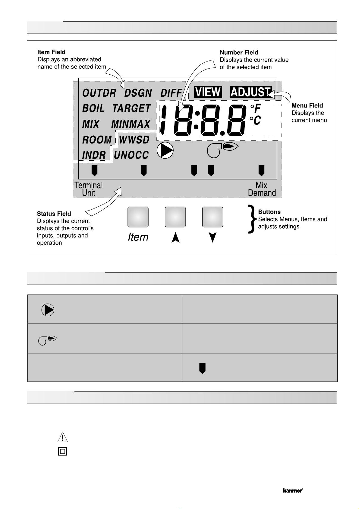
When the 360e determines that boiler operation is required, the Boiler contact terminals (7 and 8) close. While the Boiler con-
tact is closed, the burner segment in the LCD is displayed.
BOILER MINIMUM (BOIL MIN)
Most boilers require a minimum water temperature in order to prevent flue gas condensation. The BOIL MIN adjustment is set
to the boiler manufacturer’s minimum recommended operating temperature. Only when the boiler temperature is measured by
a boiler sensor can the 360e provide boiler protection. In this case when the boiler is firing and the boiler temperature is below
the BOIL MIN Setting the 360e turns on the MIN segment and reduces the heating load on the boiler by limiting the output of
the mixing valve. If the installed boiler is designed for low temperature operation, set the BOIL MIN adjustment to OFF.
BOILER PROTECTION
Refer to section A for a description of boiler protection.
BOILER SENSOR ON THE SUPPLY (Boiler Sensor DIP switch = Supply)
The boiler sensor can be located on the boiler supply if the 360e is the only control that
is operating the boiler. When in the supply mode, the 360e determines the required
operating temperature of the boiler using Boiler Load Reset. With Boiler Load Reset,
the 360e operates the boiler at the lowest possible supply temperature that is sufficient
to satisfy the requirements of the mixing valve. If this mode of operation is selected,
the boiler pump should either operate continuously, or be operated in parallel with the
system pump contact (Sys Pmp).
Note:T h e b o i l e r p u m p s h o u l d n o t b e o p e r a t e d b y t h e b o i l e r ’s a q u a s t a t , a s t h i s m a y l e a d t o
improper cycling of the boiler because of inconsistent flow past the boiler supply sensor.
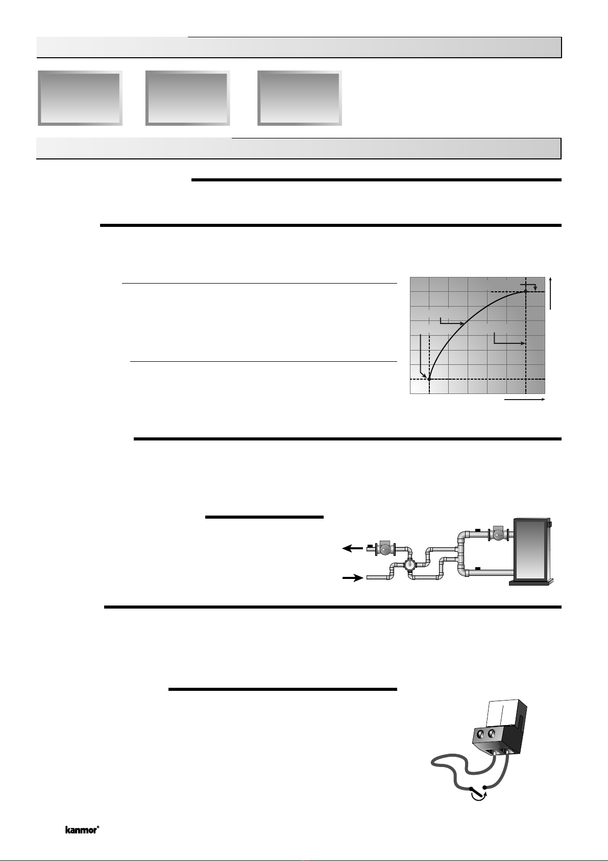
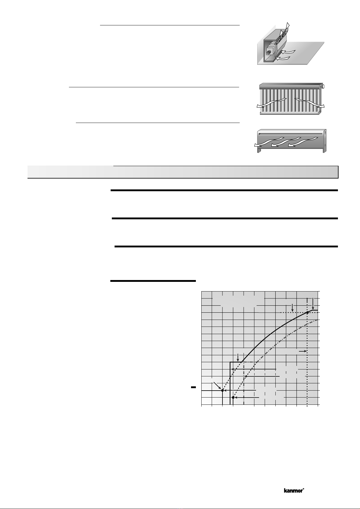
BOILER DIFFERENTIAL (BOIL DIFF)
An on / off heat source such as a boiler must be operated with a
differential in order to prevent short cycling. When the boiler supply
temperature drops below the bottom rail of the differential, the 360e
closes the Boiler contact to fire the boiler. When the boiler supply
temperature rises above the top rail of the differential, the 360e
opens the Boiler contact to turn off the boiler. With the 360e, either
a fixed or automatic differential setting is selected. If automatic dif-
ferential (Ad) is selected, the 360e automatically adjusts the boiler
differential under the current load conditions to avoid short cycling.
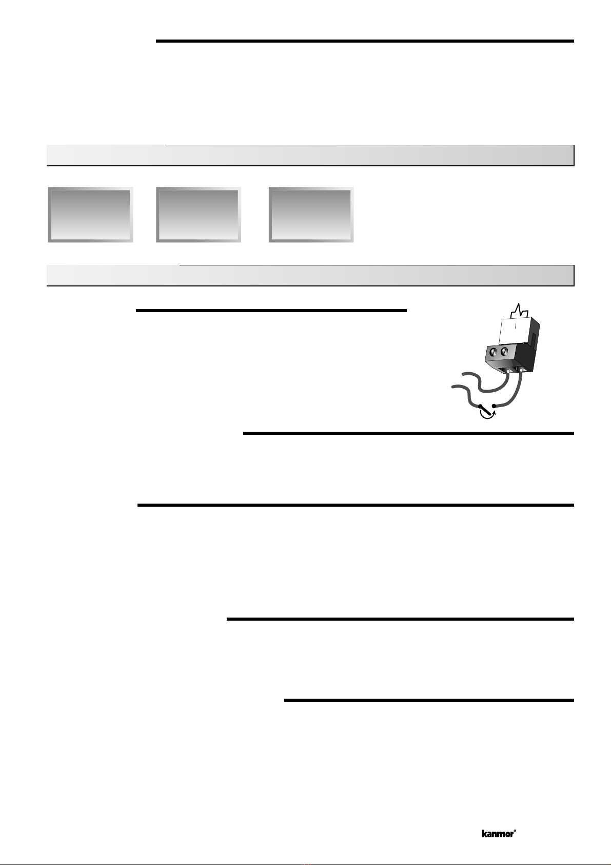
BOILER SENSOR ON THE RETURN (Boiler Sensor DIP switch = Return)
The boiler sensor should be located on the boiler return if the 360e is one of many
controls that can call for boiler operation. When in the return mode, the 360e provides
a boiler enable as described in the BOILER ENABLE section. The 360e no longer tries
to control the boiler supply water temperature directly but allows the boiler to operate
at its operating aquastat setting when required. If this mode of operation is selected,
the boiler pump should either operate continuously or be operated in parallel with the
system pump contact (Sys Pmp).
Note:T h e b o i l e r p u m p s h o u l d n o t b e o p e r a t e d b y t h e b o i l e r ’ s a q u a s t a t , a s t h i s m a y l e a d t o
improper cycling of the boiler because of inconsistent flow past the boiler return sensor.
NO BOILER SENSOR
The 360e is capable of operating without a boiler sensor if desired. Without a boiler
sensor, the 360e provides a boiler enable as described in the BOILER ENABLE section,
but is unable to provide boiler protection. This type of application is typical if the 360e is
drawing heat from a heat source t h a t a l re a d y i n c o r p o r a t e s s o m e f o r m o f b o i l e r p r o t e c t i o n .
Section C: Boiler Operation
Section C1: General Operation
Section C1
General
Operation
Section C2
Boiler Sensor
Placement
Section C2: Boiler Sensor Placement
Boiler Supply
Sensor
B
o
i
l
e
r
O
n
B
o
i
l
e
r
O
n
Time
Supply Water Temperature
Differential = 10˚F (6˚C)
165˚F (74˚C)
160˚F (71˚C)
155˚F (68˚C)
Boiler Return
Sensor
No Boiler
Sensor