Kannad aviation CS144 User manual

FAU27
Revision : 05 First Issue : JAN 14/2003
25-63-50
© Orolia S.A.S.
REF.: DOC02373G Page 1
AUG 12/2013
CS144 INTERFACE MODULE
PART NUMBER
S1825501-01 / S1825501-02
ABBREVIATED COMPONENT MAINTENANCE MANUAL
Description and Operation
TASK 25-63-50-870-801A01
1. Description and Operation
A. General
(1) Purpose
(a) The purpose of the CS144 Interface module is to combine the aircraft identification with the
aircraft position to generate the appropriate long message.
(b) The CS144 Interface module is designed to be connected between the ELT and the dongle
(that is part of the wiring to the RCP).
(c) The CS144 Interface module is compatible with all 3-Frequencies KANNAD 406 ELTs
except KANNAD 406 AS.
NOTE: 2-Frequencies KANNAD ELTs, KANNAD 406 AF-COMPACT, P/N S1840501-01,
KANNAD 406 AF-COMPACT (ER), P/N S1840501-04 and INTEGRA ELTs families P/N
S185X501-XX are not compatible with CS144 Interface module.
(d) Two versions are available:
1 CS144-RS connected to a NAV equipment by RS232, RS422 or RS485 link,
2 CS144-A connected to the NAV equipment of the aircraft via an ARINC 429 link.
(c) The CS144 Interface module is designed to be mounted on a mounting bracket 1 strap,
P/N S1820511-01.

25-63-50
© Orolia S.A.S.
Abbreviated Component Maintenance Manual
S1825501-01 / S1825501-02
Page 2
AUG 12/2013
Figure 1 / 25-63-50-991-01
General View
(2) Description (Refer to Figure 1)
Item Description
1 Housing
2 Red LED
3 J1: Female DIN 12 receptacle
4 ON/OFF switch (2 locked positions)
5 J2: Male DIN 12 receptacle
6 J3: Male 19 receptacle
7
Name Plate with the following information:
• P/N
• amendment
• serial number (S/N)
• qualification
• manufacturer name, code and details
8 Mounting bracket 1 strap (not supplied)
12
3
4
5
6
7
8

25-63-50
© Orolia S.A.S.
Abbreviated Component Maintenance Manual
S1825501-01 / S1825501-02
Page 3
AUG 12/2013
B. Technical Data
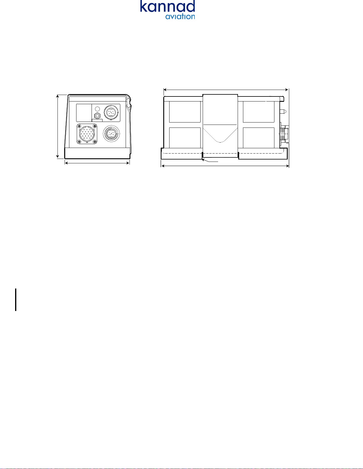
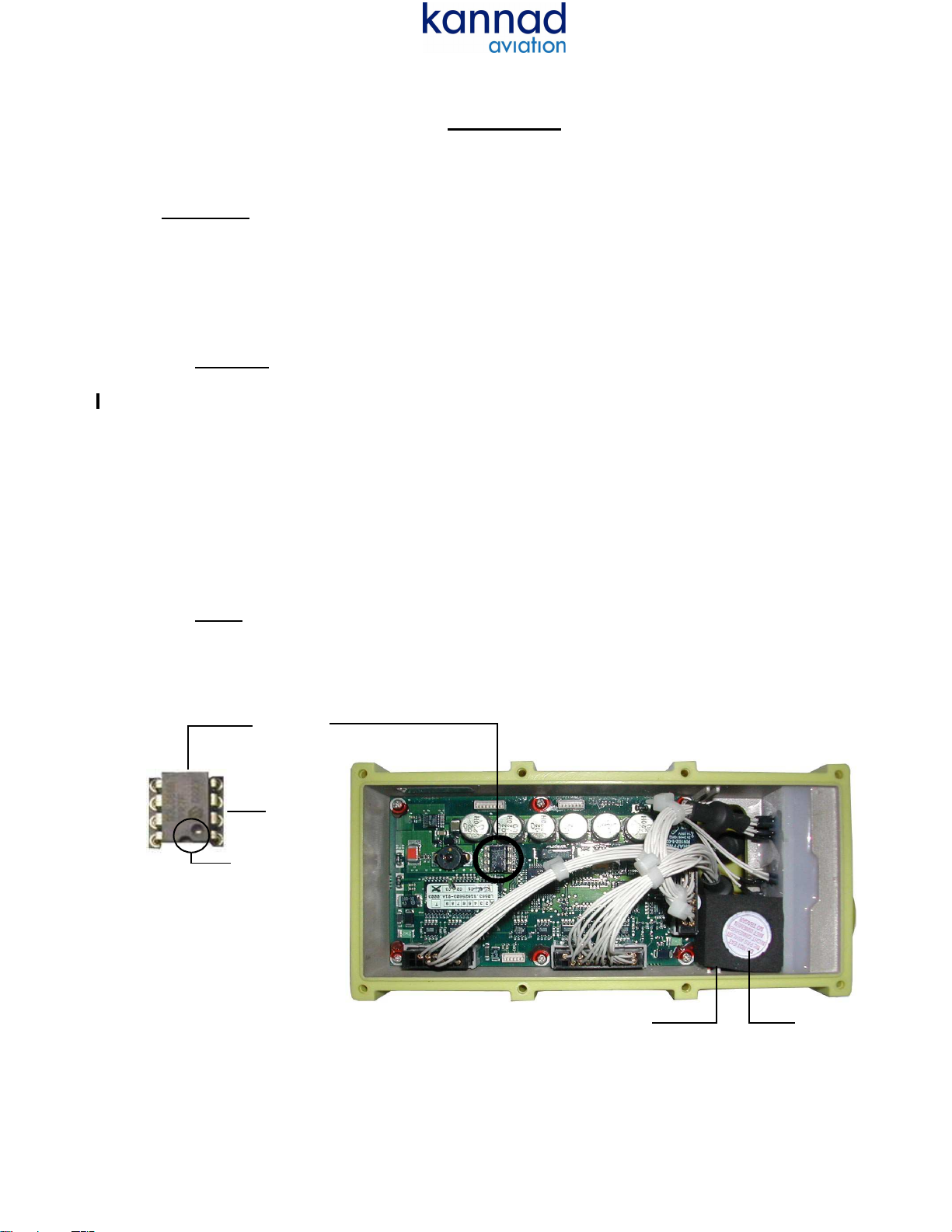
(1) Overall dimensions:Refer to Figure 2
Figure 2 / 25-63-50-991-02
CS144, overall dimensions
(2) Weight
• Typical: 650 g. (1.433 lbs).
• Maximum: 700 g. (1.543 lbs).
(3) Environmental characteristics
• Operating temperature: -55 Degrees Celsius to +70 Degrees Celsius.
• Storage temperature: -55 Degrees Celsius to +85 Degrees Celsius.
• Magnetic effects: DO 160D / ED14D Section 15 Category Z.
• Induced signal susceptibility: not applicable, length less than 1.5 m.
• Radio frequency signal susceptibility: 20 V/m CW and SW.
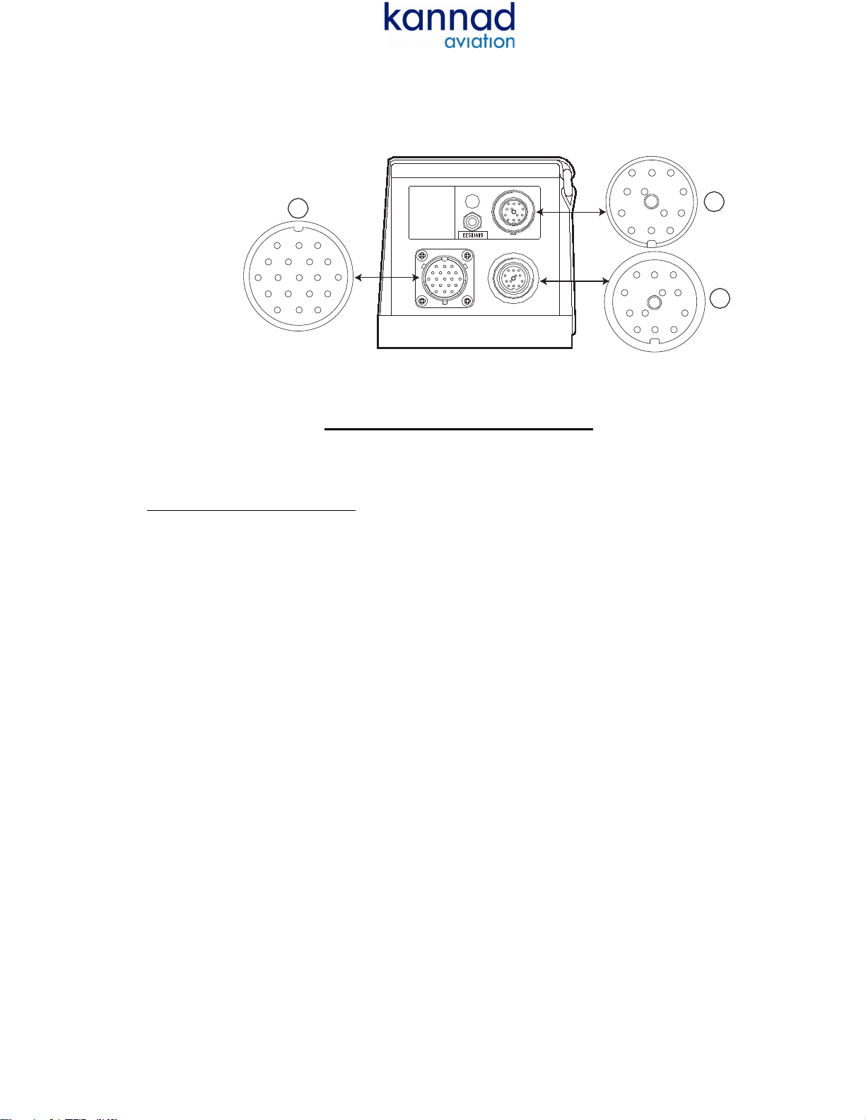
(4) Compatibility list
• The CS144 is compatible with:
- All KANNAD 406 ELTs except SURVIVAL versions, KANNAD 406 AF-COMPACT,
KANNAD 406 AF-COMPACT (ER) and INTEGRA ELTs families P/N S185X501-XX .
- All remote control panels supplied by Orolia S.A.S. (RC1xx, RC200, RC300, RC400,
RC500, RC600, RC800, RC810).
- Programming dongles, Programming dongles A320 and A320 340, Programming
dongle ASSY
- Tested with the following GPS: HONEYWELL KLN90/KLN94, GARMIN GNS430/
GNS530, TRIMBLE TNL2101 I/O Approach Plus (CS144-RS),
- NMEA 0183 or ARNAV labels A/B (CS144-RS),
- ARINC 429 labels 310/311(CS144-A).
C. Operation
(1) The CS144 Interface module constantly computes a long message by combining the short
message (identification information available in the dongle) and the aircraft position available
from the NAV equipment installed on board the aircraft.
(2) Monitoring is done through a red LED:
(a) Permanently ON when the CS144 is ON and not faulty.
(b) Fast blinking if the CS144 Interface module is faulty.
94 (3.7)
97 (3.82)
180 (7.086)
186 (7.32)
Bracket
Note: all dimensions are in millimeters
(inches in brackets)
OFF ON

25-63-50
© Orolia S.A.S.
Abbreviated Component Maintenance Manual
S1825501-01 / S1825501-02
Page 4
AUG 12/2013
D. Memory replacement
Replacement of the memory (See TASK 25-63-50-000-801A01, para D and TASK 25-63-50-400-
801A01, para B) is mandatory every 16000 flight hours or 10 years whichever comes first.
The manpower estimated time is 20 minutes.
Necessary parts to perform this task are available in an EEPROM replacement Kit, S1825515-01:
E. Upgrade
(1) CR12 replacement
Operation troubles have been identified with CS144 interface modules when connected to an ELT
with a new battery:
- the test of the ELT by RCP via CS144 may be faulty,
- the ON position of RCP may trigger a self-test on the ELT.
This is due to a battery with a high nominal voltage with regards to the clamping voltage of the CR12
protection: the CR12 protection (LCDA05) must be replaced by a protection with a higher clamping
voltage (LCDA12).
This replacement (See TASK 25-63-50-000-801A01, para E and TASK 25-63-50-400-801A01, para
C) should be performed if this failure occurs or during maintenance.
The manpower estimated time is 20 minutes
Necessary parts to perform this task are available in a CR12 replacement Kit, S1825515-02:
PART NUMBER NOMENCLATURE
1 2 3 4 5 6 7
UNIT
PER
ASSY
S1825515-01 KIT, EEPROM REPLACEMENT 1
0123841 . WEDGE, FOAM 1
0123831 . CAPSULE, DESICCANT 1
0124115 . O-RING SIL 2.4
DIA 138 1
0125267 . MEMORY CIRCUIT
93C66 DIP 8 1
0123305 . LABEL, MEMORY
(EES01670) 1
PART NUMBER NOMENCLATURE
1 2 3 4 5 6 7
UNIT
PER
ASSY
S1825515-02 KIT, CR12 REPLACEMENT 1
0123831 . CAPSULE, DESICCANT 1
0124115 . O-RING SIL 2.4
DIA 138 1
0135639 . CHIP, CIRCUIT PROTECTION
LCDA12. TB 1

25-63-50
© Orolia S.A.S.
Abbreviated Component Maintenance Manual
S1825501-01 / S1825501-02
Page 5
AUG 12/2013
Testing and Fault Isolation
TASK 25-63-50-700-801A01
1. Testing and Fault Isolation
A. General
For necessary tools and equipment, Refer to Table 9001.
B. Test after CR12 replacement
(1) Electrical test on PCB, Refer to Figure 1001.
With an ohmmeter, check that the resistor is less than 10 ohms between:
(a) R18 and pin 1 of CR12 (85),
(b) R18 and pin 2 of CR12 (85),
(c) R22 and pin 3 of CR12 (85),
(d) R22 and pin 4 of CR12 (85),
(e) the ground of PCB and pin 5, 6, 7 and 8 of CR12.
Figure 1001 / 25-63-50-991-03
Check of CR12 connections
(2) Test of LRU (housing closed), Refer to Figure 1002.
With an ohmmeter, check that the resistor is less than 10 ohms between:
(a) J1-K (RCP ON) and J2-K (RCP ON),
(b) J1-A (RCP TEST/RESET) and J2-A (RCP TEST/RESET),
(c) J1-L (DONGLE GND) and J3-D (PWR GND).
R18 R22
234
8765
CR12
Ground
To 1 & 2 of CR12
1
To R18
To 3 & 4 of CR12
To R22

25-63-50
© Orolia S.A.S.
Abbreviated Component Maintenance Manual
S1825501-01 / S1825501-02
Page 6
AUG 12/2013
Figure 1002 / 25-63-50-991-04
Check of connectors
Schematics and Wiring Diagrams
TASK 25-63-50-995-801A01
1. Schematics and Wiring Diagrams
A. General
The following abbreviations are used in the tables hereunder:
- I: Input.
- O: Output.
- N/C: not connected.
(1) J1 pin assignment
J1
J2
J3
BAM
CPNL
DRVUK
HF
G
ESTJ
A
K
B
J L C
H
M
D
G
F
E
A
K
B
J
L
C
HM
D
G
F
E
Note: Front view of connectors

25-63-50
© Orolia S.A.S.
Abbreviated Component Maintenance Manual
S1825501-01 / S1825501-02
Page 7
AUG 12/2013
Table 2001 / 25-63-50-992-01
J1 PIN Signal name Destination I/O
Viewed from
back face of mating connector
J1-A RCP TEST/RESET RCP I
J1-B DONGLE Rx DONGLE I
J1-C DONGLE Cs DONGLE O
J1-D DONGLE SK DONGLE O
J1-E DONGLE Tx DONGLE O
J1-F DONGLE ALE2P DONGLE O
J1-G RCP COMMON RCP O
J1-H RCP BUZZER RCP O
J1-J RCP LED RCP O
J1-K RCP ON RCP I
J1-L DONGLE GND DONGLE O
J1-M N/C - -
A
K
B
JL C
HM
D
G
F
E

25-63-50
© Orolia S.A.S.
Abbreviated Component Maintenance Manual
S1825501-01 / S1825501-02
Page 8
AUG 12/2013
(2) J2 pin assignment Table 2002 / 25-63-50-992-02
J2 PIN Signal name Destination I/O
Viewed from
back face of mating connector
J2-A RCP TEST/RESET ELT O
J2-B DONGLE Rx ELT O
J2-C DONGLE Cs ELT I
J2-D DONGLE SK ELT I
J2-E DONGLE Tx ELT I
J2-F DONGLE ALE2P ELT I
J2-G RCP COMMON ELT I
J2-H RCP BUZZER ELT I
J2-J RCP LED ELT I
J2-K RCP ON ELT O
J2-L DONGLE GND ELT I
J2-M N/C - -
A
K
B
J
L
C
H M
D
G
F
E

25-63-50
© Orolia S.A.S.
Abbreviated Component Maintenance Manual
S1825501-01 / S1825501-02
Page 9
AUG 12/2013
(3) J3 pin assignment Table 2003 / 25-63-50-992-03
(1)RS version
• RS232: PROTOCOL (J3-F) is strapped to PROTOCOL GND (J3-E). Data are received on RS Rx1
(J3-S) and transmitted on RS Tx1 (J3-A). The reference ground is RS GND (J3-C).
• RS422: PROTOCOL (J3-F) and PROTOCOL GND (J3-E) are not strapped. Data are received on RS
Rx1 (J3-S) / RS Rx2 (J3-T) and transmitted on RS Tx1 (J3-A) / RS Tx2 (J3-B).
(2)I1: ELT activation (when grounded).
(3)I3: ELT test or reset (when grounded).
(4)Parity check:
Without parity: strap between J3- P and J3-R.
With odd parity: no strap.
J3 PIN Signal name Destination I/O
Viewed from
back face of mating
connector
J3-A RS Tx1 Nav equipment O
J3-B RS Tx2 Nav equipment O
J3-C RS GND Nav equipment O
J3-D PWR GND A/C PS I
J3-E PROTOCOL GND
(1)
J3-F
J3-F PROTOCOL
(1)
J3-E
J3-G I1
(2)
Not used I
J3-H I2 Not used I
J3-J I3
(3)
Not used I
J3-K ARINC Rx1 (Positive input) Nav equipment I
J3-L ARINC Rx2 (Negative input) Nav equipment I
J3-M PWR Vdc Nav equipment I
J3-N I4 Not used I
J3-P ARINC PARITY
(4)
J3-R I
J3-R ARINC PARITY GND
(4)
J3-P I
J3-S RS Rx1 Nav equipment I
J3-T RS Rx2 Nav equipment I
J3-U TER RS41 Nav equipment I
J3-V TER RS42 Nav equipment I
BAM
CPNL
DRVUK
HF
G
ESTJ

25-63-50
© Orolia S.A.S.
Abbreviated Component Maintenance Manual
S1825501-01 / S1825501-02
Page 10
AUG 12/2013
Disassembly
TASK 25-63-50-000-801A01
1. Disassembly
A. General
Desiccant capsule and O-ring shall be replaced each time the CS144 is opened.
For necessary tools and equipment, Refer to Table 9001.
Refer to Figure 10001 to locate the under mentioned parts.
Refer to Figure 3001 to locate memory, desiccant capsule and foam wedge.
CAUTION: THE USE OF AN EQUIVALENT OR SIMILAR MEMORY CAN RESULT IN
MALFUNCTION (FALSE MEMORY READING BY ELT).
ONLY USE MEMORIES SUPPLIED BY OROLIA S.A.S.
B. Opening the electronic compartment
(1) Unscrew the 8 TORX screws (50) of upper lid (40),
(2) Remove the upper lid (40),
(3) Discard O-ring (90).
C. Desiccant capsule removal
(1) Remove desiccant capsule (100),
(2) Remove foam wedge (110).
D. Memory disassembly.
NOTE: To ease its replacement, the memory is not soldered but mounted on a special socket.
(1) On board I402 (70), extract the memory (80) from its socket with an extractor.
Figure 3001 / 25-63-50-991-05
Internal View
Memory
Indexing slots
Socket
DesiccantFoam Wedge
The internal memory must be
MemoryMemory

25-63-50
© Orolia S.A.S.
Abbreviated Component Maintenance Manual
S1825501-01 / S1825501-02
Page 11
AUG 12/2013
E. CR12 disassembly
(1) Disconnect connector J3.
(2) On board I402 (70), unsolder and remove CR12 (85).
Figure 3002 / 25-63-50-991-06
CR12 removal
Cleaning
TASK 25-63-50-100-801A01
1. Cleaning
A. General
(1) Clean the housing with absorbent cotton-wool (C01) soaked in alcohol (C02).
(2) Clean the connectors with a soft brush (C03) or a lint-free rag (C04). If necessary, blow them out
with low pressure dry compressed air.
Check
TASK 25-63-50-200-801A01
1. Check
A. General
(1) Make sure there is no oxidation on the pins of connectors.
Dessicant Foam wedge CR12 J3I402 Label

25-63-50
© Orolia S.A.S.
Abbreviated Component Maintenance Manual
S1825501-01 / S1825501-02
Page 12
AUG 12/2013
Repair
TASK 25-63-50-300-801A01
1. Repair
A. General
(1) Not applicable
Assembly
TASK 25-63-50-400-801A01
1. Assembly
A. General
Necessary tools and equipment: Refer to Table 9001.
Refer to Figure 10001 to locate the under mentioned parts.
B. Memory assembly
NOTE: Necessary parts to perform this task are included in "EEPROM replacement kit" (See TASK
25-63-50-870-801A01, para D, Memory replacement).
CAUTION: INSERT CAREFULLY THE LEADS OF THE MEMORY IN THE SOCKET CHECKING
THAT THE LEADS ARE CORRECTLY INTRODUCED AND NOT FOLD UP.
(1) Check the position of the indexing slots before positioning the memory on its socket (Refer to
Figure 3001).
(2) On the I402 board (70), insert the memory (80) onto its socket.
(3) Fill the memory replacement label (120) with the date of memory replacement and stick it on the
identification label (60) as shown Figure 10001 / 25-63-50-991-09 CS144 Interface module,
Illustrated Parts.
C. CR12 assembly
NOTE: Necessary parts to perform this task are included in "CR12 replacement kit" (See TASK 25-
63-50-870-801A01, para E, Upgrade).
(1) Check the position of the indexing slot before positioning CR12 (85) as shown Figure 7001 detail
A.
(2) Solder CR12 (85) on I402 board.
(3) Connect J3.
(4) As indicated Figure 7001, blacken the box B on I402 label.
(5) Carry-out the electrical test of PCB (refer to TASK 25-63-50-700-801A01, para B (1)) before
closing the CS144.
(6) As indicated Figure 7001 detail B, blacken the box B on label EES01610 stuck on the upper
cover.
(7) Carry out the LRU test (refer to TASK 25-63-50-700-801A01 para B (2)).

25-63-50
© Orolia S.A.S.
Abbreviated Component Maintenance Manual
S1825501-01 / S1825501-02
Page 13
AUG 12/2013
Figure 7001 / 25-63-50-991-07
CR12 position and labelling
D. Desiccant capsule reassembly
(1) Insert the new desiccant capsule (100) into the foam wedge (110)
(2) Install the foam wedge into the housing as shown Figure 3001 / 25-63-50-991-05 Internal View.
E. Closing the electronic compartment
Refer to Figure 7002.
CAUTION: TIGHTENING TORQUE FOR EIGHT TORX SCREWS (50): 0.9 +0, -0.1 NEWTON X
METER.
BEFORE TIGHTENING A SCREW, TURN IT COUNTER-CLOCKWISE TO FIND THE
START OF THE HOUSING THREAD (AUDIBLE CLICK).
(1) Install a new O-Ring (90) on the upper lid (40).
(2) Install the upper lid (40) in the correct assembly direction and install the eight TORX screws (50)
(3) Tighten the 8 TORX screws (50) in the sequence shown below.
Figure 7002 / 25-63-50-991-08
Cover screw tightening
64
1
7
82
3
5
FRONT

25-63-50
© Orolia S.A.S.
Abbreviated Component Maintenance Manual
S1825501-01 / S1825501-02
Page 14
AUG 12/2013
Special Tools, Fixtures, and Equipment
TASK 25-63-50-940-801A01
1. Special Tools, Fixtures, Equipment and Consumables
A. Special tools, Fixtures and Equipment
NOTE: You can use alternative tools from other suppliers if the tools has equivalent properties.
Table 9001 / 25-63-50-992-04
List of Standard Tools
NOTE: The meanings of the numbers in the USE column are as follows:
2: TESTING AND FAULT ISOLATION, 3: DISASSEMBLY, 4: CLEANING, 5: CHECK, 6: REPAIR,
7: ASSEMBLY
B. Consumables
NOTE: You can use alternative consumable from other suppliers if the consumable has equivalent
properties. Table 9002 / 25-63-50-992-05
List of Consumables
NOTE: The meanings of the numbers in the USE column are as follows:
2: TESTING AND FAULT ISOLATION, 3: DISASSEMBLY, 4: CLEANING, 5: CHECK, 6: REPAIR,
7: ASSEMBLY.
DESIGNATION CHARACTERISTICS USE
2 3 4 5 6 7
Dynamometric screwdriver FACOM A.312 or equivalent X
TORX bit (size 10) Commercially available X X
PLCC type Housing
Extractor Radiospares 424-030 or
equivalent X X
ALPHANUM.
CODE DESIGNATION SUPPLIER TRADE NAME,
ADDRESS AND FSCM USE
2 3 4 5 6 7
C01 COTTON - WOOL Commercially available X
C02 ISOPROPYL ALCOHOL PROLABO SA
54 rue Roger Salengro
94126 Fontenay sous bois
CEDEX
FRANCE
F0619
X
C03 SOFT BRUSH Commercially available X
C04 LINT-FREE RAG Commercially available X

25-63-50
© Orolia S.A.S.
Abbreviated Component Maintenance Manual
S1825501-01 / S1825501-02
Page 15
AUG 12/2013
Illustrated Parts List
TASK 25-63-50-950-801A01
1. Illustrated Parts List
A. Introduction
(1) The IPL contains a list of components used in the equipment:
• Figure items proceed by"-": Item not illustrated.
• NP: Not procurable.
• Items 80 and 120 are only procurable as part of EEPROM replacement kit S1825515-01
(see Description and Operation , para D Memory replacement).
• Item 85 is only procurable as part of CR12 replacement kit S1825515-02 (see Description
and Operation , para E Upgrade).

25-63-50
© Orolia S.A.S.
Abbreviated Component Maintenance Manual
S1825501-01 / S1825501-02
Page 16
AUG 12/2013
Figure 10001 / 25-63-50-991-09
CS144 Interface module, Illustrated Parts
NAV TO ELT INTERFACE
CS144 - RS
CAUTION :
The position of the aircraft is only
updated every 60 seconds.
This position is transmitted by the
ELT after activation.
First power up:
refer to installation - operation manual
LED Sequence
Short flash every second
Short message available
Long flash every second
Acquiring position from NAV equipment
Series of short flashes
Error
Permanent ON
Idle during 60 sec
The internal memory must be replaced every
16000 flight hours or 10 years whichever first.
Date of last memory replacement :
Database version (when applicable)
1610D
FAU27
JTSO-2C91a & JTSO-2C126
P/N :
AMDT :
S/N :
KANNAD
Z.I des Cinq Chemins - BP 23
56520 GUIDEL
FRANCE
OFF ON
40
Front view
40
50
60
View from above
120
70 Inside view from above
Cross sectional view
90
100
110
1670B
30
80
85
Date of last memory replacement :

25-63-50
© Orolia S.A.S.
Abbreviated Component Maintenance Manual
S1825501-01 / S1825501-02
Page 17
AUG 12/2013
Table 10001 / 25-63-50-992-06
Parts List
FIGURE
ITEM PART NUMBER AIRLINE
STOCK
NO.
NOMENCLATURE
1 2 3 4 5 6 7
EFF.
CODE UNIT
PER
ASSY
1- 1A S1825501-01 ASSY, ELT-NAV INTERFACE
CS144-RS RF
2-1B S1825501-02 ASSY, ELT-NAV INTERFACE
CS144-A RF
-10A S1825502-01 . UNIT, ELT-NAV INTERFACE.........................NP
CS144-RS 1A 1
-10B S1825502-02 . UNIT, ELT-NAV INTERFACE.........................NP
CS144-A 1B 1
-20A S1825503-01 . CABLE, CS144 TO ELT 1
30A 0133910 . CAP, PROTECTIVE 1
40A 0131948 . . LID 1
50A 1452K30X14 . . SCREW, SST A2 TORX SELF THR...... VF9213
(0137375) 8
60A 0123248 . . LABEL, IDENTIFICATION..................................
CS144 RS (EES01610) 1
60B 0123249 . . LABEL, IDENTIFICATION..................................
CS144 A (EES01611) 1
70A S1825603-01 . . PC BOARD, I402...........................................NP
RS 10A 1
70B S1825603-02 . . PC BOARD, I402...........................................NP
ARINC 10B 1
80A 0125267 . . . MEMORY CIRCUIT
..
.....................................NP
93C66 DIP 8 10AB 1
85A 0135639 . . . CHIP, CIRCUIT PROTECTION..................NP.
LCDA12. TB 10AB 1
90A 0124115 . . O-RING, SIL 2.4
DIA 138 1
100A 0123831 . . CAPSULE, DESICCANT 1
110A 0123841 . . WEDGE, FOAM 1
120A 0123305 . . LABEL, MEMORY.........................................NP
(EES01670) 1

25-63-50
© Orolia S.A.S.
Abbreviated Component Maintenance Manual
S1825501-01 / S1825501-02
Page 18
AUG 12/2013
TASK 25-63-50-500-801A01
1. Storage and Transportation
(1) Storage temperature: -55°C to +85°C.
PAGE INTENTIONALLY LEFT BLANK
This manual suits for next models
2
Table of contents
Popular Recording Equipment manuals by other brands

Weinzierl
Weinzierl KNX IP Interface 740.1 wireless Operation and installation manual

IK Multimedia
IK Multimedia iRig HD2 user manual

Avid Technology
Avid Technology Dock Setup

PRESONUS
PRESONUS FIREPOD - V1.0 Manual Del Usuario

Korg
Korg D16 Guide

Intelligent
Intelligent time-lapse recorder instruction manual