32
READ THIS INSTALLATION MANUAL COMPLETELY
AND CAREFULLY BEFORE ATTEMPTING
INSTALLATION
This CD- W&DVD+ W/+ drive together with software is a
product for utilizing CD- W&DVD+ W/+ recording media
with rewriting, erasing and readout capabilities, as an external
computer memory device. Except in the case where copying of
CD- OMs/DVD- OMs or me like is especially recognized under
the copyrights laws as being for the purpose of individual use by
the customer or the like, or in the case where the customer has
obtained permission to make copies from the rights holder,
reproduction of CD- OMs/DVD- OMs and copyright laws. Take
notice that unauthorized copying may be subject to claims for
damages and to Penalties.
WARNING: YOU MUST USE THE CORRECT DVD
RECORDABLE MEDIA WITH THIS DRIVE. YOU HAVE
PURCHASED A DVD+RW/R DRIVE. THIS DRIVE ONLY
RECORDS ON DVD+R AND DVD+RW MEDIA.
For CD- and CD- W recording use good quality media that
supports the maximum drive recording speed as outlined on the
drive specification page in this manual.
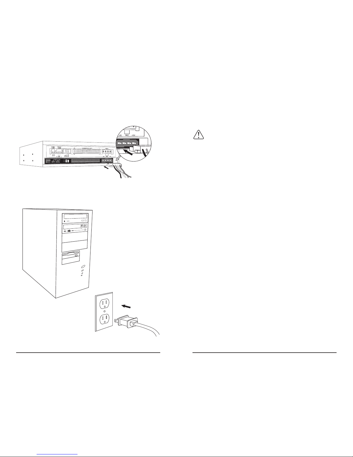
Follow the instructions in this manual and install your
DVD+ W/ Drive. Only after you have completing the drive
installation should you install any bundled software or other after
market software. When selecting DVD recording software you
must make sure that the software supports DVD+ W/ drives
and format.
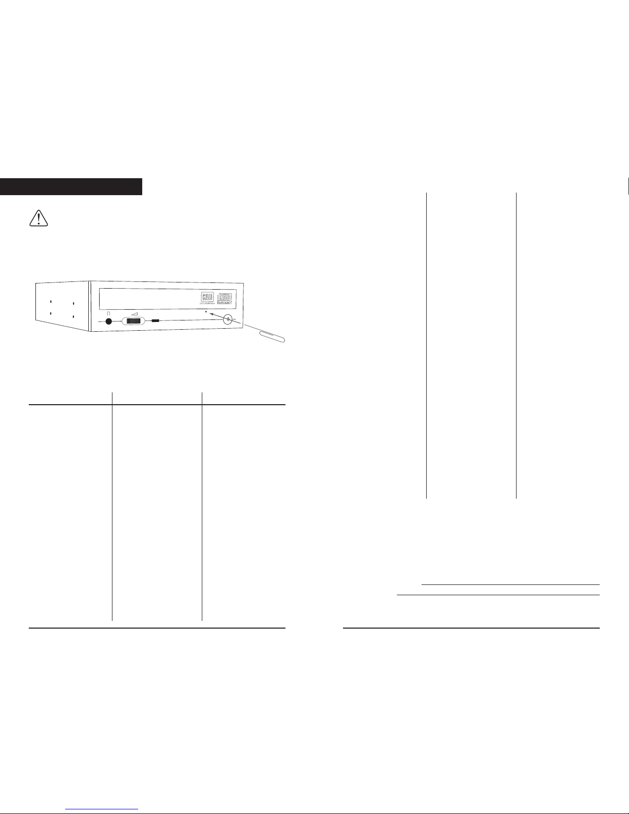
SAFETY PRECAUTIONS
PLEASE READ CAREFULLY BEFORE PROCEEDING
These precautions explain how to use the device correctly and
safely, thereby helping to prevent injury to yourself or to others
and also helping you minimize the risk of damaging the device.
Please read these sections carefully before proceeding.
WARNING
Always follow the basic precautions listed below to avoid the
possibility of serious injury or even death from electrical shock,
short-circuiting, damages, fire or other hazards. These precautions
include, but are not limited to, the following:
• Do not open the device or attempt to disassemble or modify it,
otherwise there is an increased risk of electrical shock or fire.
The device contains no user-serviceable parts. If it appears to be
malfunctioning, contact The Technical Support Department for
assistance.
• Do not look inside the device. If you expose your eyes to the
laser inside the device, you risk damage or loss of your vision.
• Do not insert fingers or foreign objects into the device,
otherwise there is an increased risk of personal injury, electrical
shock, and damage to the device or fire. Please take particular
care if small children are present.
• Do not expose the device to rain, use it near water or in damp or
wet conditions or place containers on it that contain liquids
which might spill into any openings. Otherwise, there is an
increased risk of electrical shock, fire or personal injury.
• Follow the Owner's Manual carefully otherwise, there is an
increased risk of personal injury, electrical shock, fire or damage
of the unit. Follow the correct procedure when setting up the
device.
• If unusual smells, sounds or smoke emanate from the device or
if liquids enter the device, switch the computer off immediately
and unplug it from the power outlet. Otherwise, there is an
increased risk of electrical shock, fire or damage to the device.
Call Technical Support immediately for assistance.
Read Me First