Kantronics KAM User manual

KAM
KPC-4
KPC-2400
KPC-2
KPC-1
Installation
Manual
Version 3.0 Sept. 12, 1991
RF Data Communications Specialists
1202 E. 23rd Street, Lawrence, Kansas 66046
Order number (913) 842-7745
Service number (913) 842-4476
9 am - noon, 2 pm - 5 pm Central Time, Monday-Friday

The KAM, KPC-4, KPC-2400, KPC-2 and KPC-1 are Kantronics hardware and software designs incor-
porating the AX.25 Version 2 Level 2 Packet protocol as adopted by the American Radio Relay
League. This manual contains information from earlier KPC-1, KPC-2, KPC-2400, KPC-4 and KAM
manuals and addendums, modified as appropriate. In addition, Kantronics acknowledges the use
of material from the original Tucson Amateur Packet Radio Corporation (TAPR) TNC-1 manual
granted by OEM agreement.
We have attempted to make this manual technically and typographically correct as of the date of
the current printing. Production changes to the TNC may add errata or addendum sheets. We so-
licit your comments and/or suggested corrections. Please send to Kantroncis Inc., 1202 E 23rd
Street, Lawrence, KS 66046.
Printed in the U. S. A.
© Copyright 1989 by Kantronics Inc., 1202 E. 23rd Street, Lawrence, KS 66046
All rights reserved.
Contents of this publication or the firmware described herein may not be reproduced in any form
without the written permission of the copyright owner.
NET/ROM is a registered trademark of SOFTWARE 2000
Commodore, C-64, C-128 and VIC-20 are trademarks of Commodore Business Machines, Inc.
TRS-80 Color Computer and TRS Model-100 are trademarks of Radio Shack, a division of Tandy
Corporation
Atari 850 is a trademark of Atari Inc., a Warner Communications Company
IBMPCjr is a trademark of International Business Machines Corporation
Apple and Macintosh are registered trademarks of Apple Computer, Inc.

Installation Manual
Table of Contents
Page
Radio Frequency Interference Statement .............................................. 1
RFI Suppression ....................................................................................... 1
Precautions .............................................................................................. 2
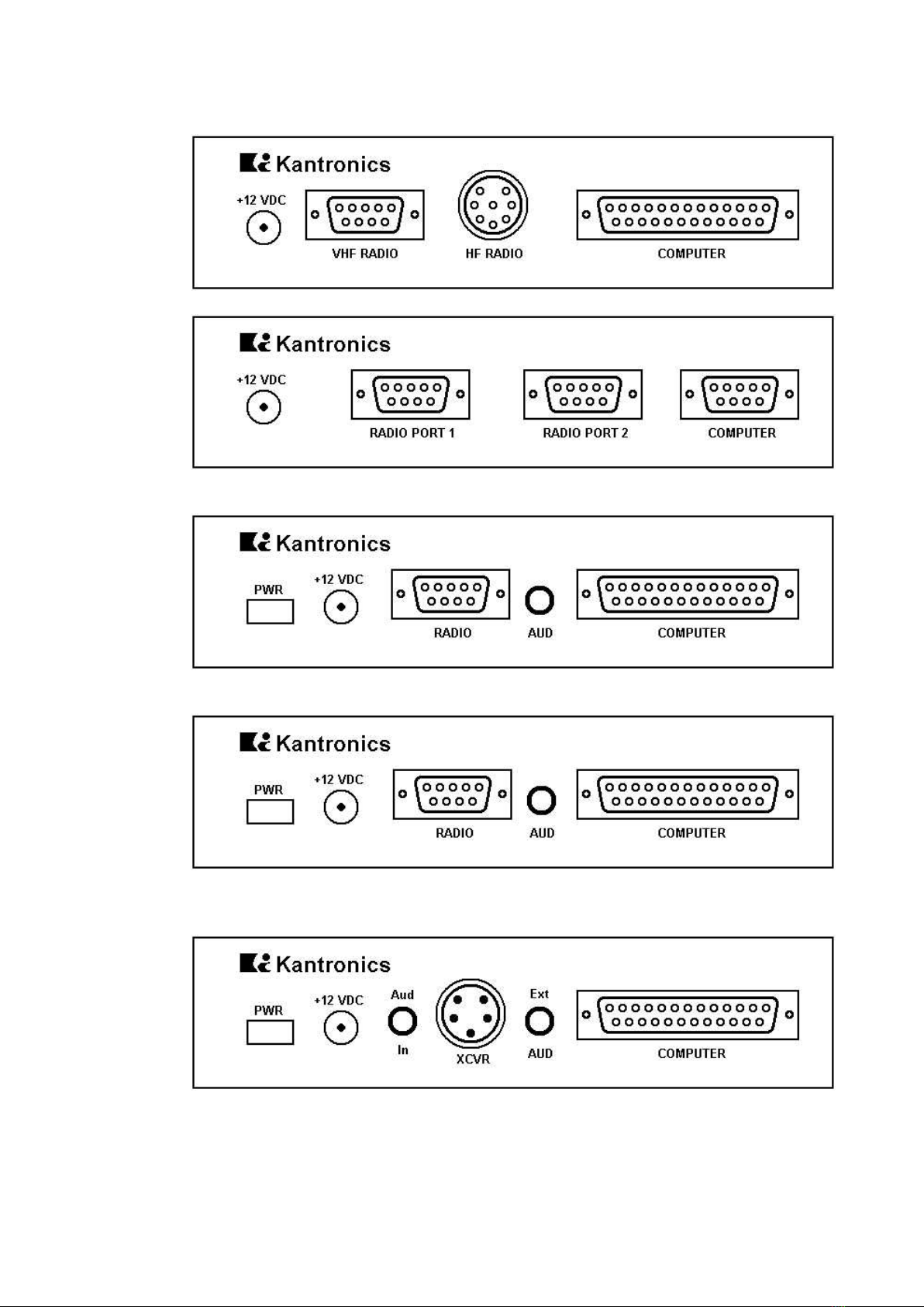
Back Panels .............................................................................................. 3
Connecting the TNC to Your Computer
RS-232/TTL Jumper .......................................................................... 4
TNC to Computer Connection ............................................................. 4
Cable Wiring ..................................................................................... 4
Other Common Computers ................................................................ 8
Commodore C-64, C-128 or VIC-20 .......................................... 8
PCjr ....................................................................................... 8
Radio Shack Color Computers .................................................. 9
TRS Model-100 ....................................................................... 9
Atai 850 Interface ................................................................... 10
Connecting Your Radios .......................................................................... 11
DB-9 Radio Connector ....................................................................... 11
8-Pin DIN Radio Connector ................................................................ 12
5-Pin DIN Radio Connector ................................................................ 14
AFSK Output Level ................................................................................... 15
KAM – AFSK Output - VHF ................................................................. 15
KAM – AFSK Output - HF ................................................................... 15
KPC-4 – AFSK Output ........................................................................ 16
KPC-2 – AFSK Output ........................................................................ 16
KPC-1 – AFSK Output ........................................................................ 16
KPC-2400 – AFSK Output ................................................................... 17
Interfacing Hand-Held Radios ................................................................. 18
In Case of Difficulty ................................................................................. 22
TNC Does Not "Sign-On" to Computer ................................................ 22
You Are Unable to Make a "Connect" .................................................. 22
Cannot Transmit on Any Port .............................................................. 22
Cannot Return to Command Mode ...................................................... 22
Kanterm Program Problems ............................................................... 23
TNC Won't Transmit on HF – VHF is OK ............................................... 23
Assembly and Disassembly of the TNC ................................................... 24
Hard Reset ............................................................................................... 25
Calibration/Equalization ......................................................................... 26
Watch Dog Timer ..................................................................................... 28

Scope Monitoring (KAM only) .................................................................... 29
Dumb Modem Mode (KPC-1, KPC-2 and KPC-2400 only) .............................. 30
Performing a Loop-Back Test (KPC-4 only) ............................................... 31
Modem Disconnect (KAM and KPC-4 only) ................................................. 32
SWDETLED Modification (KPC-1 only) ....................................................... 33
Sample Terminal Programs ..................................................................... 34
Specifications ........................................................................................... 36
Part Lists, Parts Location Diagrams, Schematics
KAM ................................................................................................. 37
KPC-4 ............................................................................................... 42
KPC-2 ............................................................................................... 45
KPC-2400 ......................................................................................... 48
PACTOR Option Addendum ..................................................................... 51

RFI
1
Radio Frequency Interference Statement
This equipment complies with the limits for a class B computing device in accordance with the
specifications in Subpart J of Part 15 of the FCC rules. These specifications are designed to mini-
mize radio frequency interference in a residential installation; however, there are no guarantee that
radio or television interference will not occur in any particular installation. If this equipment does
cause interference to radio or television reception, which can be determined by turning the equip-
ment off and on when the radio or television is on, the user encouraged to try to correct the inter-
ference by one of the following measures:
Reorient the radio or TV receiving antenna
Relocate the computer with respect to the receiver
Move the computer away from the receiver
Plug the computer into a different outlet, so that the computer and the receiver are on diffe–
rent branch circuits
If necessary the user should contact the dealer or an experienced radio/TV technician for addi-
tional suggestions. The user may find the following booklet prepared by the FCC helpful:
How to Identify and Resolve Radio-TV Interference Problems
This booklet is available from the U.S. Government Printing Office, Washington, D.C., 20402 by or-
dering Stock No. 004-00000345-4.
RFI Suppression
In moving to the world of digital communications via computer, a new dimension of RFI may be
encountered. In spite of the equipment manufactures' diligence, each new piece of electronic
equipment will react differently in each separate environment. Every amateur station will have irs
own unique layout, equipment variation and antenna installations. Experience has shown that
these differences are related to the total RF environment and my be causative factors in RFI in-
duced problems. The suggestions given here may assist in resolving RFI problems you may en-
counter in your "unique" station.
1. Use shielded cable for all connections between equipment.
2. Make all interconnecting cables as short as practical. A balance should be maintained between
cable length and equipment proximity. At times simply moving the video monitor one foot fur-
ther from an interface or other device will solve the "screen hash" problem.
3. Antenna runs should be kept away from equipment control lines and/or interconnecting cables.
If it is necessary for such lines to cross each other, they should do so at 90 degree angles.
4. Ground leads should be as short as possible and go to a GOOD EARTH GROUND.
5. Interconnecting cables appearing to act as radiators or antennas should be looped through a
toroid. Be certain toroids, if used, are designed for the frequency in use.

PRECAUTIONS
2
PRECAUTIONS
The TNC is grounded through its connections to your transceiver. Make sure your trans-
ceiver is properly grounded and your computer has equal ground potential. Follow the
grounding instructions in your transceiver manual.
Cables provided with the TNC are shielded. If you decide to use other cabling, be certain it
is also shielded. We do not recommend the use of unshielded RS-232 ribbon cable in the
ham shack environment.
Pin 25 of the DB-25 connector on the KAM, KPC-2 and KPC-2400 has 12 volts and should
never be connected to your terminal or computer port. Pin 18 in the KPC-2 is used by fac-
tory personnel only. Under no circumstances should you connect this pin to your terminal
or computer output port.

BACK PANELS
3
Back Panels
KAM
KPC-4
KPC-2
KPC-2400
KPC-1

CONNECT COMPUTER
4
Connecting the TNC to Your Computer
RS-232/TTL Jumper
Jumpers are appropriately labeled on the PC board. Refer to the parts location diagram for help in
locating them. Also refer to the Assembly and Disassembly section for information on obtaining ac-
cess to the interior of the TNC.
KAM Jumper K7
KPC-4 Jumper K10
KPC-2 Jumper K2
KPC-2400 Jumper K2
KPC-1 Jumper K2
This jumper is provided to change the TNC from RS-232 to TTL operating voltage levels. All TNCs
are shipped from the factory in the RS-232 position. If your computer operates at TTL level volt-
ages, reposition this jumper prior to placing the TNC in service.
TNC to Computer Connection
The TNC is connected to the serial data port of your computer and a terminal program must be
loaded into your computer. The serial port provides a place for data to be sent to or received from
the TNC. The terminal program is the software which runs in the computer, allowing it to commu-
nicate with the TNC. This is also sometimes called a communication program.
A few computer systems include a terminal program on the system diskette or in the initial soft-
ware package, usually named COMM, TERM or a similar name which conveys the idea of communi-
cating. Some computer system require that a terminal program be obtained separately. Several
simple terminal programs have been included in the Sample Terminal Programs section to assist
you. In general, any program which allows telephone modem communications with the computer
will be suitable for use with the TNC. A special program will be needed for the display of WEFAX
pictures.
There are generally four variables to be set in your terminal program. These are baud rate, parity,
word length (also called data bits) and the number of stop bits. If your terminal program provides
for these variables, use the following settings to talk to the TNC:
Baud rate: 300, 600, 1200, 1800, 2400, 4800 or 9600
Parity: None
Data bits: 8
Stop bits: 1
The 25-pin connector on the back panel of the TNC is for connecting to the computer. (The KPC-4
has a 9-pin connector.) When facing the back of the back of the TNC the connector on the right
side is labeled COMPUTER. See page 3 for back panel diagrams.
Cable Wiring
A cable is provided with five pre-wired lines for the connector. You must provide the connector to
attach these lines to your computer serial port. In most cases, unless the terminal program you
use requires hardware flow control, you need only connect three of these lines – Transmit Data,
Receive Data and Signal Ground. For hardware flow control, also called RTS/CTS handshaking, all
five wires in the provided cable are required.

CONNECT COMPUTER
5
Since there are so many computers on the market, it is impossible to provide interfacing informa-
tion on all of them. The following chart shows what pins are used in the TNC by name and number
and the corresponding pin to connect to for the most commonly used computer connectors. A
general rule, if you have a computer not covered here that has a serial data port, wire pins of the
same name together. Limited information on some of the other common computers will follow.
Transmit Data (TXD), Receive Data (RXD) and Signal Ground (SG) must always be
wired in order for the TNC and the computer to exchange any data. Many terminal pro-
grams also require the use of hardware flow control from the TNC. For hardware flow
control Request To Send (RTS) and Clear To Send (CTS) must also be wired. Check the
documentation toyour terminal program to see if any other wires are required. DO NOT
CONNECT ALL 25 (9) WIRES.
Some programs want to see Data Set Ready (DSR) to know that the TNC is there before operating.
If this is the case, wire both DSR and Data Terminal Ready (DTR). Or sometimes you can satisfy
the program's need by jumpering these two pins at the computer end of the cable. Data Carrier
Detect (DCD) is needed by some BBS software to know that a connection has taken place. This
would require wiring DCD. Some phone modem programs also want to see a connection before al-
lowing you to even talk to the TNC. This case can usually be solved by jumpering DCD to DTR at
the computer end of the cable. If your computer requires DSR and also DCD, it is perfectly accept-
able to jumper all three pins (DTR, DSR and DCD) together on the computer end of the cable.
Note: DCD, DSR and DTR connections are not pre-wired in the provided cable.
The TNC is wired as DCE (Data Communication Equipment). DCE equipment always send its data
on the RXD wire. DTE (Data Terminal Equipment) talks on TXD. This means that, if a computer is
wired internally as DCE and attached to the TNC, it will need to have TXD from the computer
wired to RXD on the TNC and RXD from the computer wired to TXD of the TNC. Otherwise they
will both be talking on the same wire and never hear what is said. If properly implemented by the
DCE computer, hardware flow control may be used by connecting RTS from each device to CTS on
the other device.
Caution: Make sure the power to the transceivers, computer and TNC is OFF before connecting
any cables.

CONNECT COMPUTER
6
DB-25 Connector
Male (Looking at Pins)
Female (Looking at Holes)
DB-9 Connector
Male (Looking at Pins)
Female (Looking at Holes)
TNC (DCE)
Prewired
RS-232
Computer (DTE)
Pin Name
DB-25
Pin No.
DB-9
Pin No.
Cable
Color
Direction
DB-25
Pin No.
DB-9
Pin No.
FG*
TXD
RXD
SG*
RTS
CTS
DCD
DSR
DTR
1
2
3
7
4
5
8
6
20
N/A
3
2
5
7
8
1
6
4
black
white
red
orange
green
brown
yellow
blue
purple
1
2
3
7
4
5
8
6
20
N/A
3
2
5
7
8
1
6
4
mark
space
test
+12 V
11
18
18
25
(KAM) To external scope, if desired
(KPC-2) DO NOT CONNECT TO COMPUTER
DO NOT CONNECT TO COMPUTER
*FG (Frame Ground) and SG (Signal Ground) are tied together in the TNC. The shield is on pin 1
of the DB-25 and on pin 5 of the DB-9. The black wire is not connected in the KPC-4 serial cable.
The functions of these lines are explained below:
DB-25 Pin 2
TXD
DB-9 Pin 3
Transmit Data. This line is the serial data from the terminal which is to be transmitted to the other
station by the TNC. It is this line which is used for all communication from your terminal to the
TNC, including commands.
DB-25 Pin 3
RXD
DB-9 Pin 2
Receive Data. This line is used by the TNC to send the data it receives from the other station to
your terminal. This line is also used to send TNC messages to your terminal.

CONNECT COMPUTER
7
DB-25 Pins 7 and 1
SG
DB-9 Pin 5
Signal Ground. This line establishes the common reference potential for all circuits except Protectiv
Ground.
DB-25 Pin 4
RTS
DB-9 Pin 7
Request To Send. This line tells the TNC that the terminal is ready to receive data. An ON level
tells the TNC it ma send data while an OFF level tells it to stop sending data. If the terminal for
any reason is unable to accept data from the TNC, it will cause this line to change to an OFF state,
providing that the terminal supports hardware flow control. For instance, buffer is full, terminal is
turned off and so on.
DB-25 Pin 5
CTS
DB-9 Pin 8
Clear To Send. This line is used by the TNC to tell the terminal whether or not it may send data to
the TNC. AN ON level tells the terminal it may send data while an OFF level tells it to stop sending
data. This pin is the complement to the RTS pin, implementing hardware flow control in the other
direction.
DB-25 Pin 8
DCD
DB-9 Pin 1
Data Carrier Detect. This line is an output from the TNC indicating connected status of the TNC.
When a connection exits on the current stream, this line will be true. (When using TTL levels, DCD
at +5 V indicates connected status.) This pin has no function on the KPC-1.
DB-25 Pin 6
DSR
DB-9 Pin 6
Data Set Ready. Some terminal programs look at this pin to see that the TNC is operating before
allowing you to talk to the TNC. This pin is pulled true and is common with DTR, as shipped from
the factory. In the KPC-1 DSR is jumpered to DTR and is not connected to any internal circuitry.
DB-25 Pin 20
DTR
DB-9 Pin 4
Data Terminal Ready. This pin is common with DSR in the TNC. The TNC assumes the terminal is
operating and does not require the terminal to pull this pin true. This pin may be isolated from
DSR if desired. In the KPC-1 DTR is jumpered to DSR and is not connected to any internal circuitry.
DB-25 Pins 11/18
Mark/Space
KAM ONLY
Mark/Space. These signals are available for connecting an external scope if desired. Refer to the
Scope Monitoring section for instructions.
DB-25 Pin 18
Test
KPC-2 ONLY
Processor Test Input. This is used by factory personnel only in repair and service operations. UN-
DER NOR CIRCUMSTANCES should you connect this pin to your terminal or computer output port.
DB-25 Pin 25
Plus 12 Volts
KAM, KPC-2 and KPC-2400
+12 V. This is an alternate input pin for supplying power to the TNC if desired. If the normal
+12 VDC input jack is used, this pin will be HOT. BE CERTAIN THIS PIN IS NOT CONNECTED TO
YOUR COMPUTER!
Other Common Computers

CONNECT COMPUTER
8
If you have a C-64, C-128, VIC-20, PCjr, Radio Shack Color Computer, TRS Model 100 or an Atari
850, some limited information follows. For a description of the functions of the TNC pins refer to
the previous information.
Commodore C-64, C-128 or VIC-20
If you are using an RS-232 adapter follow the previous instructions for Cable Wiring. If you are not
using an RS-232 adapter, remember to change the TNCs RS-232/TTL Internal Jumper from
RS-232 to TTL (see beginning of this chapter). Many programs will only require TXD, RXD and SG.
If using hardware flow control, RTS and CTS will also be required.
Commodore User Port
24 pin Double-Sided Card Edge Connector
Looking at Back of computer or Back (wiring side) of connector
TNC (DCE)
Prewired
Commodore
Pin Name
DB-25
Pin No.
DB-9
Pin No.
Cable
Color
Direction
User Port (TTL)
Pin ID
TXD
RXD
SG*
RTS
CTS
DCD
DSR
DTR
2
3
7
4
5
8
6
20
3
2
5
7
8
1
6
4
white
red
orange
green
brown
yellow
blue
purple
M
B & C
N
D
K
H
L
E
mark
space
test
+12 V
11
18
18
25
(KAM) To external scope, if desired
(KPC-2) DO NOT CONNECT TO COMPUTER
DO NOT CONNECT TO COMPUTER
PCjr
The IBM PCjr has a built-in terminal program in the basic cartridge. The terminal mode is started
by typing TERM. Consult the PCjr Technical Reference Manual for pin-out requirements for the PCjr
serial port. You will have to buy a special connector from your computer dealer for the PCjr.

CONNECT COMPUTER
9
Radio Shack Color Computers
The serial port of the color computer uses a 4-pin DIN plug. Pin connections at the port are shown
in the pin table below:
Pin Name
TNC DB-25
KPC-4 DB-9
Cable Color
TRS CoCo
TXD
RXD
SG
2
3
7
3
2
5
white
red
orange
4
2
3
This is known as a three-wire interface and therefore requires the use of software flow control.
This cabling supports the TRS VIDTEX program. If you have a micro-color computer, such as the
MC-10, cabling is different; consult your computer reference manual.
You may also use the Radio Shack Deluxe RS-232 Program Pak. This is a plug-in module for the
TRS-80 Color Computer line which is available from Radio Shack Stores.
The Deluxe RS-232 Pak has a standard DB-25 serial port connector to which you connect the TNC
using the following configurations:
Pin Name
TNC DB-25
KPC-4 DB-9
Cable Color
TRS RS-232
TXD
RXD
SG
2
3
7
3
2
5
white
red
orange
2
3
7
You must also install a jumper between pin 8 and pin 20 on the DB-25 connector of the Deluxe
RS-232 Pak. It is not necessary to connect RTS/CTS lines. Since these lines are not connected, you
must use software flow control. Configure the Deluxe RS-232 Pak as outlined in its operation man-
ual, select the Terminal Mode and you will be ready for Packet operation.
TRS Model-100
This computer has a standard RS-232 serial port using a DB-25 connetor wired as DTE. The inter-
nal modem program DOES NOT support CTS/RTS hardware flow control. Be sure to have the TNC
command XFLOW ON so that software flow control (XON/XOFF) will be used. You should make a
three-wire cable as follows:
Pin Name
TNC DB-25
KPC-4 DB-9
Cable Color
TRS-100
TXD
RXD
SG
2
3
7
3
2
5
white
red
orange
2
3
7

CONNECT COMPUTER
10
Atari 850 Interface
Looking at socket from outside of Interface
Pin functions of Serial Port No. 1 in 850 Interface Module 9-pin female connector:
Pin Name
TNC DB-25
KPC-4 DB-9
Cable Color
Atari 850
Interface
TXD
RXD
SG
RTS
CTS
2
3
7
4
5
3
2
5
7
8
white
red
orange
green
brown
3
4
5
7
8

CONNECT RADIOS
11
Connecting Your Radios
The TNC is attached to your transceiver(s) via the radio Connector(s) on the back panel. (See
page 3 for back panel diagrams.) The KPC-2 and KPC-2400 each have one DB-9 connector labeled
RADIO, which is used for either VHF or HF. The KPC-1 has one 5-pin DIN connector labeled RA-
DIO, which is used either for VHF or HF. The KAM has a DB-9 connector labeled VHF RADIO and
an 8-pin DIN connector labeled HF RADIO. The KPC-4 has two DB-9 connectors for VHF/UHF radio
connections labeled PORT 1 and PORT 2.
Pre-wired cables are provided with the appropriate connector for the TNC port. Two cables come
out of the connector. One with a speaker plug attached, to be plugged into the transceivers exter-
nal speaker jack. You will need to provide the mic-jack connector for your transceiver and wire the
connector to the other cable. Lines from this connector are used to control the PTT function of the
transceiver, input AFSK tones from the TNC and provide other alternate Inputs/Outputs as
described. The KPC-1 comes with two separate cables. One for audio with speaker plugs on both
ends. The other cable has a 5-pin DIN connector on the end for the KPC-1 and you will need to
provide the mic-jack connector for your transceiver and wire it to the other end of this cable.
Some rados may require adjustment of the AFSK Output Levels or Equalization of the received sig-
nals. See the AFSK Output Level and Calibration/Equalization sections for information.
Caution: Check your transceiver manual to correctly wire the corresponding pins of the transceiver
mic-jack.
DB-9 Radio Connector
Male (Looking at Pins)
Female (Looking at Holes)
Pins 1, 3, 5 and 6 must be connected to your radio.
Pin 1 – AFSK Out – white lead
This lines carries the AFSK tones generated by the TNC to the Audio Input (microphone) line of
your transceiver. If your transceiver provides a DC voltage on its microphone input, you must iso-
late this voltage from the TNC. This is normally true for hand-held radios. (See the Interfacing
Hand-Held Radio section.)
Pin 2 – XCD – yellow lead
This line may be used to connect the squelch line from your VHF transceiver if desired. This con-
nection will not normally be required, nor used, unless operating on a shared voice channel. Nor-
mally the TNC detects other signals by using its internal software to determine if data is present. If
this pin is connected, a ground potential on this pin will tell the TNC that a signal is present (even
if there is no data) and therefore prevent the TNC from transmitting until the signal is no longer
present. (See the CD parameter in the Commands Manual.)
Pin 3 – Push-To-Talk – brown lead
This line controls the PTT line in your transceiver, allowing the computer to switch the transceiver
from/to transmit or receive. Connect directly to the PTT line of the mic-jack connector (See the
section on Interfacing Hand-Held Radios for special notes concerning this pin.)

CONNECT RADIOS
12
Pin 4 – Blue lead – KAM same as pin 5
KPC-4, both ports, same as pin 5
KPC-2 same as pin 6
KPC-2400 has no connection
Pin 5 – Audio Signal – 2 conductor audio cable, center conductor and 9-wire cable, purple conduc-
tor
This line is prewired for your use as the audio input from your transceiver external speaker jack.
Do not use a headphone output from the transceiver. If you use an accessory or phone patch out-
put, it may be necessary to provide a padding network to reduce amplitude of the signal being fed
to the TNC. High level fixed outputs may have a tendency to "swamp" the TNC input circuits. Fixed
output signals in excess of 50 mV should be padded.
For the KAM and KPC-4 you can plug this lead into one leg of the Y-connector cable provided in
the TNC accessory bag. Plug the Y-connector cable into the external speaker jack of the trans-
ceiver. The remaining female connector on the Y-connector cable may be used for an external
speaker. For the KPC-2 and KPC-2400 the audio jack on the back panel remains available for at-
tachment of an external speaker.
Pin 6 – Ground/Shield – shield of 9-wire cable and shield of audio cable
Connect the push-to-talk ground and AFSK shield to this line. With some transceivers which do not
reference PTT and audio shielding to a common ground, it may be necessary to leave the AFSK
shield (braided wire) disconnected. NOTE: All TNC grounds are common.
Pin 7 – KPC-4 Radio Port 1 External Reset – red lead
An external reset line is provided on this pin. Applying a ground, either from a local or remote
source is the same as turning on the TNC. This is only on the KPC-4 Radio Port 1.
Pin 8 – Green lead – KAM same as pin 6
KPC-4, both ports, same as pin 6
KPC-2 no connection
KPC-2400 no connection
Pin 9 – Ground – Black lead – same as pin 5
8-Pin DIN Radio Connector (KAM HF)
Female (Looking at Holes)
Pins 1, 2, 3 and 6 must be connected to your radio.
Pin 1 – AFSK Out – white lead
This lines carries the AFSK tones generated by the KAM to the Audio Input (microphone) line of
your transceiver.

CONNECT RADIOS
13
Pin 2 – Ground/Shield – black and shield of 9-wire cable and shield of audio cable
Connect the push-to-talk ground and AFSK shield to this line. With some transceivers which do not
reference PTT and audio shielding to a common ground, it may be necessary to leave the AFSK
shield (braided wire) disconnected. NOTE: All TNC grounds are common.
Pin 3 – Push-To-Talk – brown lead
This line controls the PTT line in your transceiver, allowing the computer to switch the transceiver
from/to transmit or receive. Connect directly to the PTT line of the mic-jack connector.
Pin 4 – Key Out – orange lead
This line may be used to control CW keying on your transceiver. Separate a small length of this
lead and attach a lead with the appropriate plug for your transceiver key jack, where you would
normally connect a straight key.
Pin 5 – FSK Out – red lead
This line is for use if your transceiver provides FSK keying for RTTY operation. Separate a small
length of this lead and attach a lead with the appropriate plug for your FSK input connector on the
transceiver. It will also be necessary to provide for PTT keying via the mic jack, accessory port or
other method specified by your transceiver manual.
Pin 6 – Audio signal – 2 conductor audio cable, center conductor and 9-wire cable, purple conduc-
tor
Plug this lead to one leg of the Y-connector cable provided in the KAM accessory bag. Plug the Y-
connector cable into the external speaker jack of the transceiver. The remaining female connector
on the Y-connector may be used for an external speaker. Do not use a headphone output from the
transceiver. If you use an accessory or phone patch output, it may be necessary to provide a pad-
ding network to reduce amplitude of the signal being fed to the KAM. High level fixed outputs may
have a tendency to "swamp" the KAM input circuits. Fixed output signals in excess of 50 mV
should be padded.
Pin 7 – Blue lead
This pin is not connected in the KAM but the blue conductor of the 9-wire cable is attached to this
pin.
Pin 8 – XCD – yellow lead
This line may be used to connect the squelch line from your HF transceiver if desired. This connec-
tion will not normally be required, nor used, unless operating on a shared voice channel. (See the
CD parameter in the Commands Manual.)

CONNECT RADIOS
14
5-Pin DIN Radio Connector (KPC-1 Packet Communicator)
Female (Looking at Holes)
Pins 1, 2, 3 and Audio In must be connected to your radio.
Pin 1 – AFSK Out – white lead
This lines carries the AFSK tones generated by the TNC to the Audio Input (microphone) line of
your transceiver. If your transceiver provides a DC voltage on its microphone input, you must iso-
late this voltage from the TNC. This is normally true for hand-held radios. (See the Interfacing
Hand-Held Radio section.)
Pin 2 – Ground/Shield – black and stranded lead
Connect the push-to-talk ground and AFSK shield to this line. With some transceivers which do not
reference PTT and audio shielding to a common ground, it may be necessary to leave the AFSK
shield (braided wire) disconnected. NOTE: All TNC grounds are common.
Pin 3 – Push-To-Talk – brown lead
This line controls the PTT line in your transceiver, allowing the TNC to switch the transceiver
from/to transmit or receive. Connect directly to the PTT line of the mic-jack connector (See the
section on Interfacing Hand-Held Radios for special notes concerning this pin.)
Audio in
Attach a cable from the external speaker jack of the transceiver to the Audio In jack on the rear
panel of the Packet Communicator. Do not use a headphone or phone patch output from your
transceiver.
External Speaker Jack
This jack can be used to loop the audio through the Packet Communicator. Use a 3.5 mm plug and
shielded audio cable to connect to an external speaker.

AFSK OUTPUT LEVEL
15
AFSK Output Level
Audio Frequency Shift Keying
Jumpers are appropriately labeled on the PC board. Refer to the parts location diagram for help in
locating them. Also refer to the Assembly and Disassembly section for information on obtaining ac-
cess to the interior of the TNC.
KAM – AFSK Output – VHF – Jumper K2
This jumper is provided to alter the VHF AFSK output level. The KAM is shipped from the factory
with the jumper in the LO position. The LO position sets an AFSK output level from the KAM at
10 mV. The HI position sets an AFSK output level of 50 mV. Both levels are peak-to-peak values. In
general, transceivers requiring a pre-amplified microphone will also require the HI level AFSK out-
put from the KAM. Removing the jumper entirely will provide the maximum possible output level of
approximately 1.7 Vpp. Should you require an intermediate value of AFSK modulation signal, it
may be obtained by replacing resistor R12 with the appropriate value chosen from the following
chart. If you change R12 to obtain an intermediate value, place K2 in the HIGH position.
R12 Value
AFSK Output Level
470 Ω
2.2 kΩ
6.8 kΩ
22 kΩ
47 kΩ
24 mV
106 mV
290 mV
680 mV
1000 mV
KAM – AFSK Output – HF – Jumper K5
This jumper is provided to alter the HF AFSK output level. The KAM is shipped from the factory
with the jumper in the LO position. The LO position sets an AFSK output level from the KAM at
100 mV. The HI position sets an AFSK output level of 500 mV. Both levels are peak-to-peak values.
In general, transceivers requiring a pre-amplified microphone will also require the HI level AFSK
output from the KAM. Removing the jumper entirely will provide the maximum possible output
level of approximately 1.6 Vpp. Should you require an intermediate value of AFSK modulation sig-
nal, it may be obtained by replacing resistor R25 with the appropriate value chosen from the fol-
lowing chart. If you change R25 to obtain an intermediate value, place K5 in the HIGH position.
R25 Value
AFSK Output Level
680 Ω
3.3 kΩ
4.7 kΩ
6.8 kΩ
22 kΩ
48 mV
209 mV
282 mV
377 mV
800 mV

AFSK OUTPUT LEVEL
16
KPC-4 – AFSK Output – Jumpers K3 and K4
These jumpers are provided to alter the HF AFSK output level. The KPC-4 is shipped from the fac-
tory with the jumper in the LO position. The LO position sets an AFSK output level from the KPC-4
at 10 mV. The HI position sets an AFSK output level of 50 mV. Both levels are peak-to-peak values.
In general, transceivers requiring a pre-amplified microphone will also require the HI level AFSK
output from the KPC-4. Removing the jumper entirely will provide the maximum possible output
level of approximately 1.7 Vpp. Should you require an intermediate value of AFSK modulation sig-
nal, it may be obtained by replacing resistor R23 or R29 with the appropriate value chosen from
the following chart. If you change R25 to obtain an intermediate value, place the appropriate
jumper in the HIGH position.
K3 Port 1
R23 Value
K4 Port 2
R29 Value
AFSK Output Level
470 Ω
2.2 kΩ
6.8 kΩ
22 kΩ
47 kΩ
470 Ω
2.2 kΩ
6.8 kΩ
22 kΩ
47 kΩ
24 mV
106 mV
290 mV
680 mV
1000 mV
KPC-2 – AFSK Output – Jumper K1
KPC-1 – AFSK Output – Jumper K3
This jumper is provided to alter the AFSK output level. The TNC is shipped with this jumper in the
HI position. The HI position output level is 21 mVpp. In the LO position output is 4.5 mVpp. If a
higher output level is required for your radio, it may be obtained by changing the resistor (R14 in
KPC-2, R37 in KPC-1). The chart below gives the output levels for different values of the resistor
with the jumper in the HI position.
KPC-2
R14 value
KPC-1
R37 value
AFSK level
100 Ω
220 Ω
470 Ω
1 kΩ
1.5 kΩ
2.2 kΩ
8.2 kΩ
100 Ω
220 Ω
470 Ω
1 kΩ
1.5 kΩ
2.2 kΩ
8.2 kΩ
4.5 mV
10 mV
21 mV
44 mV
65 mV
94 mV
298 mV
Should you require a still higher AFSK output level, the value of the resistor may be increased fur-
ther to provide incremental increases in the same approximate ratio as that shown in the table. For
maximum output level the HI LO jumper can be removed entirely. In this case, AFSK output level
will be approximately 1.5 Vpp.
Other manuals for KAM
3
This manual suits for next models
4
Table of contents
Other Kantronics Modem manuals