Kärcher WATERCLEAN 600 CD How to use

Service Handbook
5.905-521
08.2004
Waterclean 600 CD,
LP/MP, PI
1.024-...

2
FOREWORD WTC 600 LP / MP
Service Handbook 08.2004
Foreword
Good servicing and maintenance requires comprehensive, practical training and clearly organised
documents.
This is why we offer all servicing engineers regular basic training and further qualification courses
for the whole product range.
Inaddition,wecompileservicemanualsforthemainunitswhichcanbeusedasinstructionstostart
with and as a reference work later on.
In addition, we issue regular Service Information about on-going developments of our products.
Thetextsandpicturescanonlybecopiedandduplicatedorpassedontothirdpartiesafterobtaining
explicit permission from:
ALFRED KÄRCHER GmbH & Co.
CUSTOMER SERVICE TRAINING
P. O. Box 160
D-71349 Winnenden
www.kaercher.com

3
WTC 600 LP / MP CONTENTS
Service Handbook 08.2004
Contents
1 General..........................................................................................7 - 10
1.1 Introduction ........................................................................................................... 7
1.2 Marking of Instructions ........................................................................................ 7
1.3 Intended Use.......................................................................................................... 7
1.4 Safety Instructions................................................................................................ 8
1.4.1 Quality of the Untreated Water .................................................................................8
1.4.2 Chlorination of DrinkingWater ..................................................................................8
1.4.3 Disposal of Chemicals .............................................................................................8
1.4.4 Handling Electricity / Protection Class .....................................................................9
1.5 General installation notes .................................................................................. 10
1.6 Units and Designations .......................................................................................11
2 Description ................................................................................ 11 - 20
2.1 Overview .............................................................................................................. 11
2.2 Flow Diagram ...................................................................................................... 13
2.3 Description of the System.................................................................................. 14
2.3.1 Modular Design ......................................................................................................14
2.3.1.1 Pre-chlorinationModule......................................................................................... 14
2.3.1.2 FlocculationModule............................................................................................... 14
2.3.1.3 Mediafilter- and Activated Carbon Filter ................................................................ 15
2.3.1.4 RO System, Pump and Fine Filter ........................................................................ 15
2.3.1.5 Control Panel and Display..................................................................................... 15
2.3.1.6 Anti Scalant and Post Chlorination ........................................................................ 15
2.3.1.7 Pressure-increase Pump ...................................................................................... 16
2.3.2 Safety Installations .................................................................................................16
2.3.3 Operating Modes....................................................................................................17
2.3.3.1 Automatic Operation (Standard Operating Mode) ................................................. 17
2.3.3.2 Manual Operation .................................................................................................. 17
2.4 Technical Data WTC 600 LP/MP ......................................................................... 18
2.5 Consumption Materials ...................................................................................... 20
2.5.1 Chemicals for Metering Container..........................................................................20
2.5.2 Cleaning Chemicals ...............................................................................................20
2.5.3 Filter .......................................................................................................................20
3 Operation of the System.......................................................... 21 - 43
3.1 Assembly and Starting Operation ..................................................................... 21
3.2 Mixing Chlorine, Flocculation Agent and Antiscalant ..................................... 22
3.2.1 Initial Starting of Operation .....................................................................................22
3.2.2 Pre-chlorination ......................................................................................................22
3.2.3 Antiscalant..............................................................................................................24
3.2.4 Metering Amounts and Mixing of the Post Chlorination ..........................................25
3.2.5 Flocculation Agent..................................................................................................25
3.2.5.1 Mixing of the flocking test solution..........................................................................25

4
CONTENTS WTC 600 LP / MP
Service Handbook 08.2004
Contents
3.2.5.2 Perform flocking test...............................................................................................26
3.2.5.3 Evaluate flocking test .............................................................................................26
3.3 Connecting the Equipment ................................................................................ 27
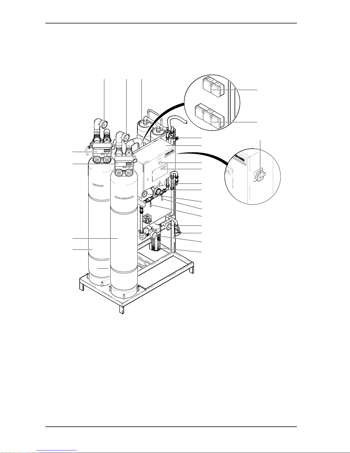
3.3.1 Connections, Valves and Indicators.......................................................................27
3.3.1.1 Pressure-increase Module .................................................................................... 28
3.3.1.2 RO Module with Preliminary Filters....................................................................... 28
3.3.2 Electrical Connections ...........................................................................................29
3.3.2.1 Pressure-increase Pump ...................................................................................... 29
3.3.2.2 Preliminary Filter ................................................................................................... 29
3.3.2.3 MeteringStation .................................................................................................... 29
3.3.2.4 Float Switch........................................................................................................... 31
3.3.2.5 Reverse Osmosis System.................................................................................... 31
3.4 Starting Operation ...............................................................................................31
3.4.1 MeteringStation .....................................................................................................31
3.4.2 Media filter and activated carbon filter ....................................................................32
3.4.2.1 InitialFilling ............................................................................................................ 32
3.4.2.2 Starting Operation ................................................................................................. 32
3.4.2.3 Backwashing / Regeneration ................................................................................ 32
3.4.2.4 Programming......................................................................................................... 33
3.4.3 Starting Operation of the RO System ....................................................................35
3.4.3.1 Operating Levels and Passwords ......................................................................... 35
3.4.3.2 Menu Selection...................................................................................................... 35
3.4.3.3 Selection of an Option ........................................................................................... 35
3.4.3.4 Selecting Several Arguments at the Same............................................................ 36
3.4.3.5 Adjusting Operating Parameters and Balancing Values .........................................36
3.4.3.6 Acknowledging Data Inputs .................................................................................. 36
3.4.3.7 OperationalInterruptions....................................................................................... 36
3.4.3.8 Initial startup...........................................................................................................38
3.4.4 Normal Operation ...................................................................................................40
3.4.4.1 Operating Messages for Normal Operation .......................................................... 41
3.4.5 Putting Out of Operation.........................................................................................42
3.4.6 Disinfection.............................................................................................................43
4 Maintenance.............................................................................. 44 - 62
4.1 Fine Filter ............................................................................................................. 44
4.2 Metering Station WTC 600 CD............................................................................ 44
4.3 Reverse Osmosis Module (RO Module) ............................................................ 45
4.3.1 RO Filter Replacement...........................................................................................45
4.4 Cleaning in Case of Malfunction........................................................................ 46
4.4.1 Design of the Flushing and Disinfection Equipment ...............................................47
4.4.2 Disinfection.............................................................................................................49
4.4.3 Acidic and Alkaline Cleaning ..................................................................................50
4.4.3.1 Cleaning Solution for Acidic Cleaning ................................................................... 51

5
WTC 600 LP / MP CONTENTS
Service Handbook 08.2004
4.4.3.2 Cleaning Solution for Alkaline Cleaning................................................................. 51
4.4.4 Conserving.............................................................................................................51
4.4.4.1 Draining and rinse the metering stations ................................................................51
4.4.4.2 Conserve RO systems ..........................................................................................51
4.4.4.3 Draining the pre-filter ..............................................................................................53
4.4.5 Removing the Preservation After Longer Operational Interruptions.......................53
4.4.6 Rinsing the pre-filter ...............................................................................................54
4.4.7 Replacing the activated carbon or filter sand .........................................................55
4.5 Malfunction, Cause and Corrective Action ....................................................... 57
4.5.1 Metering Station LED and Indicator LEDs at the Switch Cabinet...........................57
4.5.2 Malfunction Indication at the Operating Panel ........................................................58
4.5.3 Malfunctions of the RO Control and Metering Pump ..............................................59
4.5.4 Malfunctions – Sand and Activated Carbon Filter, Fine Filter and Flocculation......60
4.6 Maintenance Plan ................................................................................................ 61
4.6.1 Maintenance During Operation...............................................................................61
4.6.2 Maintenance Plan Service .....................................................................................62
Appendix ................................................................................... 63 - 84
RO control manufacture settings .......................................................................... 63
RO control program structure ............................................................................... 65
RO 1000: User manual...........................................................................................67
Operating Record for the WTC 600 LP/MP........................................................... 84
List of key words .............................................................................86 - 88
Contents

WTC 600 LP / MP
6Service Handbook 08.2004

7
WTC 600 LP / MP GENERAL
Service Handbook 08.2004
1 General
1.1 Introduction
This service manual contains basic instructions and information which are to be observed upon
set-up, operation andmaintenance.
Therefore, it is imperative that the service manual is read by the installer as well as by the
responsible specialist staff prior to installation and starting of operation.Please observe not only
the general safety instructions listed in the section “Safety Instructions”, but also the special
safety instructions included in the other sections.
1.2 Marking of Instructions
The safety instructions contained in these operating instructions, which in case of
non-observance can cause dangerous situations for persons, are specially marked
with the general symbol for dange.
The safety instructions contained in these operating instructions, which in case of
non-observance can cause poisoning, cauterizing, etc. for persons, are specially
marked with the death’s-head symbol.
Following this symbol are recommendations or tips which make working easier and
provide for secure operation.
Following this symbol are recommendations or tips which make working easier and
provide for secure operation.
Instructions that are attached directly to the equipment must be observed under all means and
kept in completely readable condition.
1.3 Intended Use
The equipment is intended for the conditioning of untreated water into drinking water.
The retention degree of harmful chemical substances and biological pathogens or contaminants
is very high.
The quality of the produced drinking water ultimately depends on the contamination degree and
salt content of the untreated water.
- Prior to the initial starting of operation, we recommend carrying out an analysis of the
untreated water.
- Continuous drinking-water quality can be ensured only when the equipment is controlled
regularly.
- The respective national or international drinking water regulations are to be observed.
Under consideration of these rules of conduct, water produced from this system can quite safely
be classified as drinking water.
CAUTION
NOTE

8
GENERAL WTC 600 LP / MP
Service Handbook 08.2004
1.4 Safety Instructionse
1.4.1 Quality of the Untreated Water
Sufficient quality of the untreated water must be ensured!
Faultless drinking water is achieved only when all filters of the equipment are
maintainedregularly.
1.4.2 Chlorination of Drinking Water
When applying post chlorination, the limit values set by national laws must be main-
tained.The chemicals used have a caustic and fire-promoting effect.
Dangers:
- Danger of fire in case of contact with combustible materials.
- Toxic gas develops when coming in contact with acids.
- Heat or direct sunlight decomposes the chemical: Chlorine and oxygen are released.
- Caustic effects to the eyes, skin and respiratory system result.
Safety Instructions:
- Wear acid-resistant protective equipment (goggles, gloves) and when dust is produced,
breathing mask protection with a filter.
- Keep an eye wash bottle (small) readily available.
- Provide for adequate room ventilation and a washing facility.
- Store the chemicals in a cool, dry place, not below 5 °C.
- Store chemicals in a location out of the reach of children.
In Case of Accidents:
- In case of contact with the eyes, rinse immediately and thoroughly with fresh water and
consult a doctor.
- Use water to extinguish; avoid impact and friction.
- If solutions are spilt, flush the area with a sufficient amount of fresh water.
1.4.3 Disposal of Chemicals
It is generally recommended to admit resulting disinfection solutions, preservation solutions, etc.
into a neutralizing system.
If this should not be possible, the disinfection solution, after clarification with the relevant
authority (mayor’s office, district administration office, etc.) is to be neutralized and can
afterwards be led into the public sewer system.

9
WTC 600 LP / MP GENERAL
Service Handbook 08.2004
1.4.4 Handling Electricity / Protection Class
Be aware of dangerous electrical voltage!
For work on components/assemblies which are marked with this symbol, protective
measures are to be taken:
- Switch off the power
- Secure against restarting
- Check and assess that no voltage is given.
The electrical connection of the equipment may be carried out only by a qualified
electrician.
The power supply cable must be fitted with a protective conductor
(protection class I).
1.5 General installation notes
- Only use food safe components and resources on the drinking water side
- Pay special attention to hygienic cleanliness when installing drinking water pipes.
1.6 Units and Designations
Unit Designation
bar bar (pressure)
di/da Diameter, inside / diameter, outside
g/h Gram per hour
Hz Hz (frequency)
l Liter
l/h Liter per hou
mg/h Milligramper hour
mg/l Milligramperlite
ml Milliliter
V AC Volt (AC)
W Watt (power)
°dH Degree of hardness (water hardness)
µS/cm Microsiemens per cm (spec. conductance value
ETL Spare parts list
LW Conductance value
SLP Circuit Diagram
Table 1 Units and their meaning
1000 milliliter = 1 liter; 1000 mg = 1
NOTE

10
DESCRIPTION WTC 600 LP / MP
Service Handbook 08.2004
2 Description
2.1 Overview
Figure 1 Overview of components
1.3
e
2.2
a
b
1.2 2.1 4.12,4.13
f
g
4.23
c
d
4.24
4.21
4.14
4.11
4.15
4.17
4.4
4.3
4.7
4.5, 4.6

11
WTC 600 LP / MP DESCRIPTION
Service Handbook 08.2004
Legend for figure 1 and figure 2:
1.1 Pre-chlorinationmetering point
1.2 Manometer - media filter inlet pressure
1.3 Mediafilter
1.4 Differential pressure switch
1.5 Concussion restrictor
1.6 Flocculationmeteringpoint
2.1 Manometer - activated carbon filter
inlet pressure
2.2 Activated carbon filter
4.1 Antiscalant metering point
4.2 Non-return valve
4.3 Untreated water sampling tap
4.4 Manometer - fine filter input pressure
4.5 Fine filter housing
4.6 Fine filter candle
4.7 Manometer - fine filter output pressure
4.8 Input solenoid valve
4.9 Manostat
4.10 High-pressure pump
a Media filter control
b Control, activated carbon filter
c Control cabinet
d Manual / automatic rotary switch
e Master switch
f Media and activated charcoal
plug sockets
g Power outlets (3x) for metering
stations
Items 1.1 to 6.4 are attached to the components as reference numbers.
4.11 Manometer, pump pressure
4.12 Membrane pressure pipe
4.13 Membrane
4.14 Manometer - concentrate pressure
4.15 Concentrate control valve
4.16 Concentrate flowmeter
4.17 Pressure control valve
4.18 High-pressure pump
4.19 Conductivity and temperature
measuring cell - drinking water
4.20 Drinking water flowmeter
4.21 Drinking water sampling tap
4.22 Non-return valve
4.23 Post chlorination metering point
4.24 Reverse osmosis control
6.1 Pre-chlorinationmetering
6.2 Antiscalant metering
6.3 Post chlorination metering
6.4 Flocculationmetering

12
DESCRIPTION WTC 600 LP / MP
Service Handbook 08.2004
2.2 Flow Diagram
Figure 2 Flow diagram of the complete reverse osmosis system (RO system)

13
WTC 600 LP / MP DESCRIPTION
Service Handbook 08.2004
2.3 Description of the System
2.3.1 Modular Design
The installation is a drinking water conditioning system. Its core application is the
emineralization of brackish water with a salt content up to 2000 ppm (WTC 600 LP), respectively
up to 5000 ppm (WTC 600 MP).
The design of the system is modular, and can be adapted accordingly to the local conditions
depending on the application conditions as well as the composition of the untreated water:
- Media filter and flocculation – module 1
- Activated carbon filter – module 2
- Reverse osmosis system – module 4
- Pressure-increase pump – module 5
- Metering stations
The RO system is designed for stationary use.
2.3.1.1 Pre-chlorination Module
The WTC 600 CD metering station, consisting
of metering container (3/1) and pump (3/2), is
connected to the sand filter module for pre-
chlorinationifrequired.
2.3.1.2 Flocculation Module
The WTC 600 CD metering station (see figure 3) with injection adapter is connected to the sand
filter module for pre-flocculation if required.
The exact requirement of flocculation agent is to be determined when starting operation (see
Section 3.2.5).
Figure3 WTC600CD
1
2

14
DESCRIPTION WTC 600 LP / MP
Service Handbook 08.2004
2.3.1.3 Mediafilter- and Activated Carbon Filter
The pre-filter units of the RO system consist of the media filter and the activated carbon filter.
The filter fillings consist of support pebbles and filter sand according to DIN 19623, as well as
activated carbon.
The filters are each controlled by means of a central control valve with microprocessor control
and located at the top of the filter.
The fine filter is located on the front side of the
equipment. It is connected directly in front of
the RO system.
The RO pump (4/2) pumps the pre-filtered
water through two RO filters (4/1) which are
connected in series.
2.3.1.5 Control Panel and Display
The control panel is used for data input in the
control and as LED indicator for the operating
modes and malfunction indications (5/1).
Parameters are entered with the arrow
pushbuttons. Data input is acknowledged with
the ENTER pushbutton (5/4) and cancelled
with the ESC pushbutton (5/3).
Programming conditions, etc., are indicated in
the display (5/2).
2.3.1.6 Anti Scalant and Post Chlorination
For hardness stabilization of the untreated water and post chlorination of the drinking water a
WTC 600 CD metering station is connected to the RO module in the same manner as for pre-
chlorination.
Figure5 Controlpanelanddisplay
Figure4 ROpump
1
2
2
14
3
2.3.1.4 RO System, Pump and Fine Filter

15
WTC 600 LP / MP DESCRIPTION
Service Handbook 08.2004
2.3.1.7 Pressure-increase Pump
If required, the WTC 600 PI pressure-increase
pump (6/1) is connected between untreated
water supply and RO system. It is used for
pressure increase of the untreated water.
A pressure-increase pump should
be used for a water pressure (flow
pressure) ⱕ2 bar.
Observe mechanical protection as
well as protection of the
connection cable against water!
2.3.2 Safety Installations
Emergency Stop
The emergency stop switch (7/4) (main switch) is located on the side of the switch box.
RC Protective Switch
RC protective switch (external): i ⱕ30 mA
Circuit Breaker
Automatic circuit breaker (7/3) 10 A for power limitation of the power outlets, etc
Motor Protection Switch
The motor protection switch (7/2) is factory-set depending on the power consumption of the RO
pump (compare circuit diagram (7/1)) and must be checked:
WTC 600 Nominal output Actual power Motor protection
RO pump consumption switch setting
LP 400 V 2.2 kW 1.5 kW 4 A
MP 400 V 2.2 kW 2.2 kW 5.1 A
LP 230V 2.2 kW 1.5 kW 10 A
MP 230 V 2.2 kW 2.2 kW 14 A
Table 2 Setting of motor protection switch
Figure6 WTC 600 PI
1
NOTE
CAUTION

16
DESCRIPTION WTC 600 LP / MP
Service Handbook 08.2004
Microfuses
Two microfuses (7/6) for protection of the
control electronics (7/5) are located on the
control board for the electronics:
- 5x20 6,3 A time-delay
- 5x20 0,1 A time-delay.
Figure7 Switch cabinet and control electronic
2.3.3 Operating Modes
2.3.3.1 Automatic Operation (Standard Operating Mode)
After switching on the main switch, the system is fully automatic controlled through the
electronic control system and the float switch in the drinking water tank.The mode selector
switch is in the “Auto” position.
The control system usually operates in the normal plane in the operating mode operation.
With the exception of an error acknowledgement (only in case of pre-selection Vw-
acknowledgement by actuating the ESC key button), no further operating by the operator is
possible; this is to protect the control system against unintended / unauthorized manipulations.
By entering the respective password, the user level or the technician level for input
of operating parameters, etc.is cleared (see section 3.4.3.1).The program structure
is given in the appendix, Figure 21.
Operating parameters and setting values are listed on the data sheet by the
manufacturer (cf.Tables 34 and 35).
2.3.3.2 Manual Operation
The float switch in the drinking water tank is deactivated by the manual / automatic rotary switch
("Manual" position), so that the plant can run continuously.
Manual operation is not standard operating mode, as the system does not switch off
automatically.
2
14
35
6
NOTE
NOTE
CAUTION

17
WTC 600 LP / MP DESCRIPTION
Service Handbook 08.2004
2.4 Technical DataWTC 600 LP/MP
Parameter WTC 600 LP WTC 600 MP
Ambienttemperature +1°C - +50°C
Storage temperature (delivery) to -10°C
Humidity <100% r.F.
Supply voltage 3*400V 50 Hz1)
1*230V 50 Hz1)
Pre-filter controls: prim / sec. 230 V/12 V 50 Hz
Metering pumps 230 V 50-60Hz
Wiring 3 Ph, N, PE
Electrical protection 16 A
Connected electrical load 2.2 kW 2.2 kW
Effective electrical power consumption 1.5 kW 2.2 kW
Mechanical protection / protection against water
Switch cabinet IP44
Pump and valves IP44
Meteringpump IP44
Power outlets (plug inserted) < IP44
Minimum temperature of untreated water +5°C
Maximum temperature of untreated wate +35°C
Reference temperature +15°C
pH-value, untreated water 6-9.5
pH-value during cleaning 3-11
System input pressure and flow 2-6 bar at min. 2 m³/h
Capacity range 15000 l/day (±10%)
Maximum drinking water capacity 650 l/h
Dimensions: H x W x D
WTC 600 LP/MP 1800 x 660 x 720 mm
WTC 600 LP/MP - A 1800 x 1120 x 720 mm
WTC 600 LP/MP - AM 1800 x 1120 x 720 mm
Weight in delivery condition (without filter container)
WTC 600 LP/MP 135 kg
WTC 600 LP/MP - A 155 kg
WTC 600 LP/MP - AM 175 kg
Table 3 Technical Data
1) depending on the system version

18
DESCRIPTION WTC 600 LP / MP
Service Handbook 08.2004
Filter Container
Volume per container 103 l
Filling capacities, Mediafilter
Support pebbles 2.0 - 3.15 mm 15 kg
Filter sand 0.4 - 0.8 mm 100 kg
Filter amounts, activated carbon filter
Support pebbles 1 - 2 mm 15 kg
Activated carbon filter F100 32 kg
Water connections
Inlet threaded connection hose nozzle Outer diameter d25
Drinking water threaded connection hose nozzle Outer diameter d25
Concentrate threaded connection hose nozzle Outer diameter d25
Outlet for flushing water HT pipe d50
Canal connection (supplied by customer) > DN 50
Hydraulic Data
Maximum allowable flow rate in filteroperation 1,3 m3/h
Amount of waste water produced during 2 m³/h, ca. 670 liter per backwashing
backwashing
Allowable Operating Conditions
Maximum pressure 6 bar
Metering Pump
Feed capacity at max. counter-pressure (10 bar) 1 l/h
MeteringContainer:
Weight with pump 10 kg
Connections
Hose connections (PE) di/do 4/6
Hose connection, ventilation (PVC) di/do 4/6
Float Switch
Minimum hysteresis 300 l
Table 4 Technical Data

19
WTC 600 LP / MP DESCRIPTION
Service Handbook 08.2004
2.5 Consumption Materials
Swear protective equipment and observe safety instructions!
2.5.1 Chemicals for Metering Container
For mixing of the metering solution, use the measuring cup with the handle (250 ml or 1000 ml).
Explanations of the units, see Chapter 1.6.
A metering container from the WTC 600 CD metering station has a volume of 75 liter.
Product ItemNo.
Chlorinatedlime 6.291-505.0
Sterilization agen RM 852 6.291-772.0
RM 5000 hardness stabilization 6.290-991.0
RM 5001 Flockulents, 10 l 6.294-703.0
RM 5001 Flockulents, 60 l 6.294-716.0
Table 5 Kärcher Original Products
2.5.2 Cleaning Chemicals
Product Item No.
RM Kleen MCT 511 6.294-008.0
RM Kleen MCT 103 6.294-009.0
RM P3 Oxonia Active 6.294-010.0
RM 1,2 Propandiol, 5 l 6.290-910.0
Sulfite 5 kg 6.769-040.0
Soda 6.287-014.0
RM 511 Vaporapid bio-descaling acid 6.290-239.0*
Table 6 Cleaning Chemicals * Attention! Note national variants!
2.5.3 Filter
Product Item No.
Filterelement5µ 6.414-466.0
Replacement set, metering pump 6.762-172.0
Table 7 Filter Elements
NOTE
NOTE

20
OPERATION OF THE SYSTEM WTC 600 LP / MP
Service Handbook 08.2004
3 Operation of the System
3.1 Assembly and Starting Operation
Assembly Chapter
Checking the scope of delivery (delivery note)
Placing the equipment in the set-up location and positioning
Connecting the untreated water to the WTC 600 LP/MP; connecting 2.2,3.3.2.1, 3.3.1
the WTC 600 PI in between, if required (depending on delivery scope)
Installing the piping for backwashing and drinking water 2.2
Installing the float switch 3.3.2.4
Filling and connecting the sand filter and the activated carbon filter 3.4.2
Connecting the electrical system SLP, 3.3.2
Table 8 Assembly work to be carried out upon starting operation
Starting Operation Chapter
Establishing the untreated water supply 2.2
Manually actuating the sand filter backwashing 3.4.2
Manually actuating the activated carbon filter backwashing 3.4.2
Flushing the reverse osmosis 3.4.3.7
Filling the chemicals container 3.2
Adjusting the flow rates 3.4.3.8
Filling out the metering table in the operating instructions
Instructing the operator (operating instructions)
Table 9 Overview of start-up work
A water analysis with the following values must exist for commissioning of the WTC 600:
- Total hardness GH in °dH
- Iron Fe in mg/l
- Manganese Mn in mg/l
- Ammonium NH4or NH3in mg/l
- System yield determined by the sales department (Normal case: 75%, in special cases 50%).
This manual suits for next models
3
Table of contents
Other Kärcher Water System manuals
Popular Water System manuals by other brands

clage
clage Zip HydroTap G5 BC 20 operating instructions

clage
clage Zip HydroTap G4 BCS 100/75 Operating and installation instructions

KSB
KSB BOA-H operating manual

ZURN
ZURN Z1315 Guide

clage
clage Zip HydroTap G5 BCS 60 Operating and installation instructions

BIO UV
BIO UV MP 100 Installation and maintenance manual

KSB
KSB MIL 90000 Installation & operating manual

DynaQuip Controls
DynaQuip Controls WaterCop owner's manual

T&S
T&S B-0133-B Installation and maintenance instructions

AVK
AVK DN80 Installation & maintenance instructions

CEFLA
CEFLA PURE 500 operating manual

clage
clage Zip HydroTap G4 CS 175 Operating and installation instructions