KARMETAL KMT 180 CRAFT User manual

KK54(15.07.2016/00)
KMT
180 CRAFT
OPERATION MANUAL
*Main photo may feature optional accessories of the machine

2
MACHINE CERTIFICATION AND
IDENTIFICATION MARKING
NOTE: This manual is a part of the machine. It must be supplied with the
machine in case of any transport or sale.
ATTENTION!
BEFORE USING THE MACHINE, PLEASE READ THIS
MANUAL CAREFULLY. ALL EXPLANATIONS,
INSTRUCTIONS AND WARNINGS ARE INTENDED TO
PROTECT YOU!

3
EC DECLARATION OF CONFORMITY
The manufacturer declares that the machinery described herein
conforms to the following EC directives and harmonised standards
and relevant essential health and safety requirements.
Manufacturer: KARMETAL SAN. & TIC. LTD. STI
Address: Hanlı Merkez Mah. Hatip Sok. No:32 Arifiye/Sakarya/ TÜRKİYE
Phone: +90 264 276 59 16 (3 lines)
Fax: +90 264 276 59 19
Web: www.karmetal.com.tr
e-mail: [email protected]
Machine type/model: KMT 180 CRAFT Manual Miter Bandsaw Machine
Applicable EC Directives:
Machinery Directive 2006/42/EC,
Low Voltage Directive (LVD) 2006/95/EC and
Electromagnetic Compatibility (EMC) Directive 2004/108/EC
Applicable Harmonized Standards:
TS EN ISO 12100–1 (2007), TS EN ISO 12100–2 (2006), TS EN ISO 13850 (2007),
TS EN 953 (1998), TS EN ISO 13849–1 (2007), TS EN 1088 (2005), TS EN ISO 60204–1 (2008)
Approved By:
Name : Fatih KAR
Position : Factory Manager
Signature :
Place/Date : SAKARYA / 18.07.2016

4
WARRANTY CONDITIONS
The machine is under the warranty of KARMETAL LTD. ŞTİ. for a period of 2 years for
mechanical parts, 1 year for electric and electronic parts from the date of purchasing. This
warranty is subjected to all of the terms and conditions listed below:
1. This warranty is valid only if the Warranty Registration Form is filled in and returned
to the manufacturer or its authorized dealer within two months after the date of
purchasing.
2. The obligation of the manufacturer under this warranty shall be limited to repairing or
replacing components which proves defective and which our examination shall
disclose to our satisfaction to be defective.
3. Defects due to improper operation, misuse, neglect, alteration, irregular voltage
conditions, inadequate wiring, improper installation (all electrical and electronic
components, all electrical motors etc.) and due to accidents or any damage caused
by transportation, flood, fire, natural disasters, theft are not included in this warranty
and are strictly the responsibility of the purchaser.
4. Any part returned to KARMETAL or its authorized dealer under the terms of this
warranty shall be on the basis of transportation charges prepaid by the customer and
must be accompanied by a record of the machine model code and serial number.
5. This warranty does not apply to the following components; band saw blade, blade
pressure pads or brackets and blade guide bearings because of being
consumables.
6. Manufacturer and authorized dealer cannot be blamed within maximum repair period
for the material or moral damage. Apart from that act the period as Warranty
Conditions and there will not be done any retroactive requirement.
KARMETAL SAN. & TIC. LTD. STI.
Dealer:

5
Important!
This form must be fully completed and returned to the manufacturer or its authorized dealer
within two months after the date of purchasing. Failure to do so will void the warranty.
WARRANTY REGISTRATION FORM
Machine Model : …………………………………………………………
Serial Number : …………………………………………………………
Invoice Date : …………………………………………………………
Invoice Number : …………………………………………………………
Dealer:
…………………………
Customer:
…………………………

6
CONTENTS
1SAFETY............................................................................................................................8
1.1 Safety Rules.................................................................................................................8
1.2 Danger Zones on the Machine.....................................................................................9
1.3 Safety Equipments On The Machine.........................................................................10
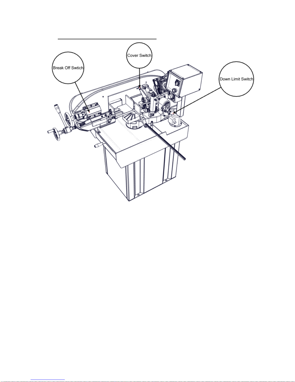
1.3.1 Break-off Switch ................................................................................................11
1.3.2 Cover Switch......................................................................................................11
1.3.3 Down Limit Switch............................................................................................11
1.3.4 Emergency Stop Button .....................................................................................11
1.4 Warning Labels and Assignments.............................................................................12
1.4.1 Glove Label........................................................................................................12
1.4.2 Electricity Neutral Warning Label .....................................................................12
1.4.3 High Voltage Label............................................................................................12
1.4.4 Safety Equipments Label ...................................................................................12
1.4.5 Arrow Label .......................................................................................................12
2DESCRIPTION AND PROPERTIES..........................................................................13
2.1 Technical Specifications of the Machine...................................................................13
2.2 Standard Equipment ..................................................................................................13
2.3 Noise Level................................................................................................................13
2.4 Machine Dimensions.................................................................................................14
2.5 Properties Table According to Forms of Swarf.........................................................15
2.6 KMT 180 CRAFT Bandsaw Machine Cutting Capacity...........................................15
3TRANSPORTATION AND INSTALLATION...........................................................16
3.1 Handling the Unpacked Machine..............................................................................16
3.2 After Unpacking the Machine ...................................................................................16
3.3 Environmental Conditions.........................................................................................16
3.4 Machine Placement and Position...............................................................................16
4PREPARATION BEFORE OPERATION..................................................................17
4.1 Cleaning.....................................................................................................................17
4.2 Lubricating.................................................................................................................17
4.3 Coolant.......................................................................................................................17
4.4 Electrical Power Connection.....................................................................................17
4.5 Final Inspection Checklist before Operation.............................................................17
5OPERATION..................................................................................................................18
5.1 Control Panel.............................................................................................................18
5.2 Blade Changing Procedure........................................................................................20

7
6MAINTENANCE...........................................................................................................23
6.1 Daily Maintenance.....................................................................................................23
6.2 Weekly Maintenance.................................................................................................23
6.3 Monthly Maintenance................................................................................................23
6.4 Six-Monthly Maintenance.........................................................................................23
6.5 Periodic Maintenance................................................................................................24
7TROUBLESHOOTING ................................................................................................25
8DISMANTLING.............................................................................................................26
9SPARE PART LIST.......................................................................................................27
9.1 BASE ASSEMBLY...................................................................................................29
9.1.1 BASE UPPER FRAME .....................................................................................30
9.1.2 BASE LOWER FRAME....................................................................................31
9.2 FLANGE JOINT ASSEMBLY.................................................................................32
9.3 VISE ASSEMBLY....................................................................................................33
9.4 BOW ASSEMBLY....................................................................................................35
9.5 BOW LIFTTING CYLINDER ASSEMBLY ...........................................................37
9.6 BLADE GUIDE ASSEMBLY..................................................................................38
9.6.1 FIXED BLADE GUIDE ASSEMBLY..............................................................39
9.6.2 MOBILE BLADE GUIDE ASSEMBLY ..........................................................40
9.7 GEARBOX ASSEMBLY..........................................................................................41
9.8 BLADE TENSIONING ASSEMBLY ......................................................................42
9.9 HYDRAULIC CONTROL PANEL..........................................................................43
9.10 SPRING ASSEMBLY...........................................................................................44
9.11 ELECTRIC GROUP..............................................................................................45

8
1SAFETY
1.1 Safety Rules
Never allow unqualified persons to operate or interfere with the machine.
It is important to develop personal safety awareness. Observe all related safety
regulations and pay attention for hazardous conditions. Discuss these conditions with
your supervisor.
•You must use personal protective equipment, like safety glasses, gloves, safety work
shoes.
•Do not remove warning signs and/or instruction plates off the machine.
•Do not open/remove any door or guard during operation.
•Make sure that all machine controls are set for the desired mode of operation,
whenever the setting of the machine control is changed, run the machine in slow mode
to make sure it operates as expected.
•Never disable any safety device to avoid its assigned function. These devices are
intended to protect both the machine and its operator.
•Do not load, unload, operate or adjust the machine without proper instructions.
•This machine is specifically designed for cutting general metal material. Do not cut
wood and analogous material, meat, fishery, food and agriculture products, combustible
and radioactive materials.
•Enough space should be provided around the machine to avoid hitting and provide a
convenient operation.
•Do not leave any tool on the machine after use. Do not put work stock or tools around
the machine, to avoid injury.
•Do not operate the machine with its safety guards removed.
•Do not wear gloves when operating through control panel.
•Wear gloves only when loading/unloading the material, changing the blade and chip
brush.
•Never touch the blade, moving work stock, nor put your hands into the vise area or chip
conveyor unit until the machine halts completely.
•When selecting blade, blade speed and coolant, please refer to the operation manual or
related documents.
•Before installation and operate the machine check the sufficiency of the earth of the
machine to your electrician. Do not operate the machine without the earth.
•Determined and declared bench life of the machine by the Ministry of Industry and
Trade is 10 years.
•For longevity please follow the maintenance directions at the manual.

9
1.2 Danger Zones on the Machine

10
1.3 Safety Equipments On The Machine

11
1.3.1 Break-off Switch
This switch is used for to stop the machine while the blade pressure
gets smaller than adjusted ones. The main causes of decrease in
pressure are; dulling, cracking or breaking of blade. Operating the
machine under these conditions endanger the operator.
1.3.2 Cover Switch
This switch provides to shut down the machine while the bow
cover is open. Running the machine may cause wounding and
serious gashes. Machine gives aural warning while the cover is
open.
1.3.3 Down Limit Switch
This switch is used to adjust the bow’s nadir to goes down. Down
limit switch is a factory setting. Please do not tinker with the down
limit switch.
1.3.4 Emergency Stop Button
Emergency stop button, places on the operator control panel-
near the main switch, is red button and you can see it easily. In
emergency cases, press to this button to stop the machine.
Machine does not run while the button is pressed. To rerun the
machine, please turn left and release the button.

12
1.4 Warning Labels and Assignments
1.4.1 Glove Label
Please use personal protective equipment, like glove, during
operation and changing the blade.
1.4.2 Electricity Neutral Warning Label
In this label, we declared the instructions how to make the electric connection before
installing machine or after handling the machine.
1.4.3 High Voltage Label
This label shows high voltage risk parts. All electrical connections
should be done by a qualified electrician.
1.4.4 Safety Equipments Label
All the safety devices and guards are designed
to intend to protect the operator. Please do not
remove these safety guards.
1.4.5 Arrow Label Blade’s direction of rotation belongs to machine
type. Arrow label on the machine shows blade’s
direction of rotation. Please pay attention on
direction of rotation while changing blade.

13
2DESCRIPTION AND PROPERTIES
2.1 Technical Specifications of the Machine
MAIN MOTOR
0,75 kW
COOLANT PUMP
0,09 kW
CUTTING SPEED
25-90 m/min
BLADE DIMENSIONS
2310x20x0,9 mm
BLADE QUALITY
Bi Metal
HEIGHT OF VISE BED
915 mm
WEIGHT
200 kg.
MACHINE DIMENSIONS
600x1450x1400 mm
NUMBER OF PHASE
Mono Phase
FREQUENCY
60 Hz
2.2 Standard Equipment
Inverter
Hydromechanical Band Tension
Fast Clamping Arm
Speed Adjustable Hydraulic Cylinder
One Way Miter Till 60°
Adjustable Length Setting Bar
Adjustable Tension Band Wheel
1 Bandsaw Blade
2.3 Noise Level
In accordence with the Machinery Directive 2006/42/EC
The A-weighted continous acoustic pressure does not exceed 70 dB (A).
The maximum level of the C-weighted instantaneous acoustic pressure is always less
than 130 dB.
NOTE: With the machine operating, the noise level will vary according to the different
materials being processed and setting up.The user must therefore assess the intensity and if
necessary provide the operators with the necessary personal protection.

14
2.4 Machine Dimensions

15
2.5 Properties Table According to Forms of Swarf
2.6 KMT 180 CRAFT Bandsaw Machine Cutting Capacity
Forms of
Swarf
Shape of
the swarf
Thick,
hard and
short
Thick,
hard and
brittle
Thick,
hard and
curled
Thick,
hard and
curled
Thin,
spiral and
curled
Thin,
spiral
and
curled
Like
dust
Thin and
very
curled
Colour of
the swarf
Blue or
brown
Blue or
brown
Silver or
yellow
Silver
Silver
Silver
Silver
Silver
Bandsaw
speed
Decreas
e
Decrease
Suitable
Increase
Suitable
Suitable
Decreas
e
Suitable
Advance
speed
Decreas
e
Decrease
Decreas
e a little
Decrease
Suitable
Increase
Increase
Decrease
The
others
Check
lubricant
coolant
level
Check
lubricant
coolant
level
Check
number
of teeth
Check
number
of teeth
Use thick
pitch saw
0°
45°
60°
180 mm
140 mm
90 mm
170 mm
140 mm
85 mm
160 x 210 mm
160 x 140 mm
160 x 85 mm

16
3TRANSPORTATION AND INSTALLATION
3.1 Handling the Unpacked Machine
Make sure the machine is safely loaded and balanced when moving it with a forklift, failing to
do so may cause personal injury or damage to the machine.
3.2 After Unpacking the Machine
Put the machine in a dry and sheltered place to prevent damage to the electrical and mechanical
components. Apply appropriate lubricant (machine oil or grease) on the slide ways and non-
painted areas to prevent rust.
3.3 Environmental Conditions
Mains voltage and frequency complying with the machine motor characteristics.
Environment temperature from -10° C to 50° C.
Relative humidity is %5 to %90.
3.4 Machine Placement and Position
The followings should be considered when positioning the machine:
The floor: The machine should be placed on a levelled concrete floor.
Working area: Sufficient space should be allocated around the machine for comfortably
loading and unloading work stock and for easy access during maintenance and repair. When
necessary, all doors and access panels should be opened without interference.
Lighting: The machine and its surroundings should be well lit for operator’s safety and for a
convenient operation and maintenance.

17
4PREPARATION BEFORE OPERATION
4.1 Cleaning
Unpainted and uncoated machine surfaces were coated with a rust inhibitor prior to
shipment. The rust inhibitor should be cleaned with an appropriate solvent. To prevent
rust on unpainted surfaces, a light coat of machine oil can be applied.
4.2 Lubricating
Lubricate all the sliding parts before starting.
4.3 Coolant
The machine is shipped with the coolant reservoir empty. Fill the reservoir with coolant
until it is full.
Caution: Do not run the coolant pump without coolant in the reservoir. Otherwise, the
coolant pump will be damaged.
4.4 Electrical Power Connection
1. Electrical connection must be done by a qualified electrician, in conformance with the
required electrical standards of your area.
2. Turn off the main circuit breaker of the area in which the machine will be located.
3. Machine's power cord should be connected to an appropriate power source; make sure the
voltage rate matches the one required for the machine.
4. It is important that the shipping brace should be removed from the saw before taking any
further step.
Note: If the ‘emergency stop button’ is depressed, it must be released for the machine to run.
4.5 Final Inspection Checklist before Operation
After installing the machine, a final inspection should be performed by considering the
following checklist;
Any missing components, guards or panels
Lost fasteners and fittings, hoses and conduit
Missing or damaged items
Coolant, oil, or hydraulic leads
Tools and others materials left on saw
Safety measures, general condition and readiness for use

18
5OPERATION
In this section, the functions of the machine will described to guide the operator to become
familiar with the machine and its components.
5.1 Control Panel
The following figure shows a general view of the machine control panel. The control elements on the
panel will be described next.
Main Power Switch
When this switch is turned on, the LCD display comes on, indicating that the machine is
ready to operate.
Emergency Stop
The "Emergency stop" push button stops all functions of the machine. The machine will not
function until "Emergency stop button’ is released. To release the emergency button, turn it in
the direction indicated on its hub.
Caution: The "Emergency stop" push button does not disconnect the machine from the main
power supply. To avoid from serious injury or death due to electricity shock, turn the main
power switch off or disconnect the machine from the main supply before servicing it.
Coolant Pump On/Off Button
Coolant pump can be switched on and off via this button.
Caution: Do not run the coolant pump without coolant in the reservoir. Otherwise, the coolant
pump will be damaged.

19
Cutting Speed Control Buttons
Cutting speed can be controlled via this button in the range of 25 –90 m/min. Set value can
be seen at the LCD.
Start/Stop Button
Cutting process can be switched on and off via this button
Flow Control Valve
Downward stroke speed of the bow can be controlled via this valve.
Vane
When this vane is closed, the bow cannot be moved
up/down. When it’s opened, downward stroke speed of
the bow can be controlled via flow control valve and
upward stroke of the bow can be done manually.

20
5.2 Blade Changing Procedure
In order to achieve accurate and efficient cuts, it is important to use a sharp and correct blade
for the material to be cut.
1- Raise the saw frame to its highest position
2- Turn the hand-wheel to left to loosen the blade.
3- Switch off the main power switch of the machine.
Caution: Avoid serious injury by turning the machine's power off at the main switch before
adjusting, servicing, or cleaning the saw.
4- Open all the wheel covers on the saw frame.
5- Loosen the bolts on the carbide blade guides.
Lower the blade from bandsaw guides.
Table of contents
Other KARMETAL Saw manuals