KARMETAL KMT 280 WOS User manual

KK47(24.01.2017/00)
KMT
280 WOS
OPERATION MANUAL

2
MACHINE CERTIFICATION AND IDENTIFICATION
MARKING
NOTE : This manual is a part of the machine and must accompany it if
moved within the company or sold.
ATTENTION!!!
BEFORE USING THE MACHINE, PLEASE READ THIS
MANUAL CAREFULLY. ALL EXPLANATIONS,
INSTRUCTIONS AND WARNINGS ARE INTENDED TO
PROTECT YOU!

3
EC DECLARATION OF CONFORMITY
The manufacturer declares that the machinery described herein conforms to
the following EC directives and harmonised standards and relevant essential
health and safety requirements.
Manufacturer: KARMETAL SAN. & TIC. LTD. STI
Address: Hanlı Merkez Mah. Hatip Sok. No: 32 Arifiye/Sakarya/ TURKEY
Phone: +90 264 276 59 16 (3 lines)
Fax: +90 264 276 59 19
Web: www.karmetal.com.tr
e-mail: [email protected]
Machine type/model: KMT 280 WOS Automatic PLC Controlled Band Saw Machine
Applicable EC Directives:
Machinery Directive 2006/42/EC,
Low Voltage Directive (LVD) 2006/95/EC and
Electromagnetic Compatibility (EMC) Directive 2004/108/EC
Applicable Harmonized Standards:
TS EN ISO 12100–1 (2007), TS EN ISO 12100–2 (2006), TS EN ISO 13850 (2007),
TS EN 953 (1998), TS EN ISO 13849–1 (2007), TS EN 1088 (2005), TS EN ISO 60204–1
(2008)
Name : Fatih KAR
Position : Factory Manager
Signature :
Place-Date : SAKARYA / 17.04.2013

4
WARRANTY CONDITIONS
The machine is under the warranty of KARMETAL LTD. ŞTİ. for a period of 2 years for
mechanical parts 1 year of electric and electronic parts from the date of purchase. This
warranty is subject to all of the terms and conditions listed below:
1. This warranty is valid only if the Warranty Registration Form is filled in and
returned to the manufacturer or its authorized dealer within two months after the
date of purchase.
2. The obligation of the manufacturer under this warranty shall be limited to repairing
or replacing components which proves defective and which our examination shall
disclose to our satisfaction to be defective.
3. Defects due to improper operation, misuse, neglect, alteration, irregular voltage
conditions, inadequate wiring, improper installation (all electrical and electronic
components, all electrical motors etc.) and due to accidents or any damage caused
by transportation, flood, fire, natural disasters, theft are not included in this
warranty and are strictly the responsibility of the purchaser.
4. Any part returned to KARMETAL or its authorized dealer under the terms of this
warranty shall be on the basis of transportation charges prepaid by the customer
and must be accompanied by a record of the machine model code and serial
number.
5. This warranty does not apply to the following components; band saw blade, blade
pressure pads or brackets and blade guide bearings because of being
consumables.
6. Manufacturer and authorized dealer cannot be blamed within maximum repair
period for the material or moral damage. Apart from that act the period as Warranty
Conditions and there will not be done any retroactive requirement.
KARMETAL SAN. & TIC. LTD. STI.
Dealer:

5
Important!
This form must be duly completed and returned to the manufacturer or its authorized dealer
within two months after the date of purchase. Failure to do so will void the warranty.
WARRANTY REGISTRATION FORM
Machine Model : …………………………………………………………
Serial Number : …………………………………………………………
Invoice Date : …………………………………………………………
Invoice Number : …………………………………………………………
Dealer:
…………………………
Customer:
…………………………

6
Contents
MACHINE CERTIFICATION AND IDENTIFICATION MARKING.............................. 2
ATTENTION!!!.................................................................................................................... 2
EC DECLARATION OF CONFORMITY .......................................................................... 3
WARRANTY CONDITIONS.............................................................................................. 4
WARRANTY REGISTRATION FORM............................................................................. 5
CHAPTER I : SAFETY................................................................................................ 7
1. Safety Rules .................................................................................................................. 7
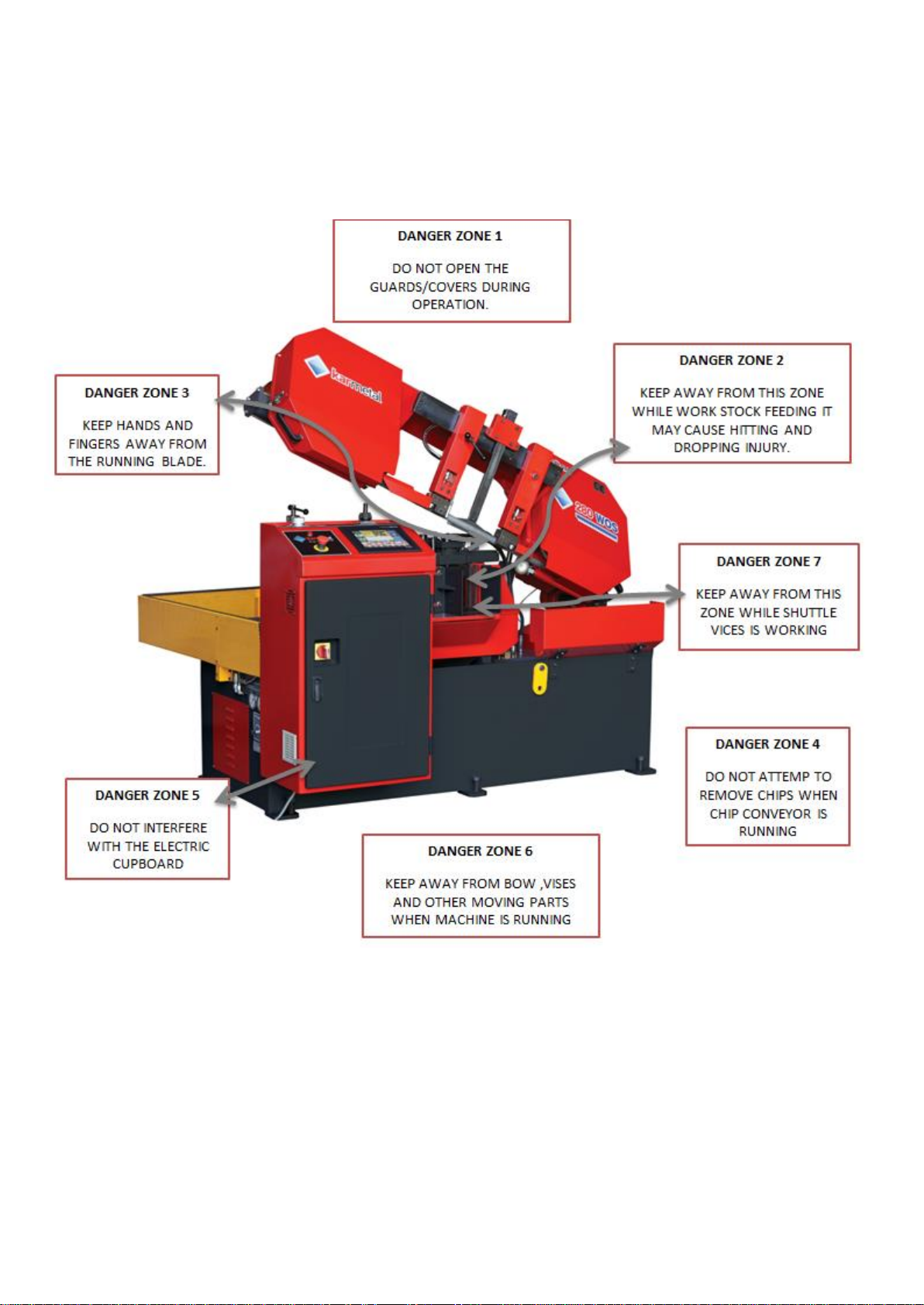
2. Danger Zones on the Machine...................................................................................... 8
3. Safety Equipments and Assignments............................................................................ 9
4. Warning Labels and Assignments .............................................................................. 12
CHAPTER II : DESCRIPTION AND PROPERTIES ............................................... 13
1. Technical Properties of the Machine .......................................................................... 13
2. Standard Equipment.................................................................................................... 13
3. Optional Equipment.................................................................................................... 13
4. Noise Level................................................................................................................. 13
5. Machine Dimensions .................................................................................................. 14
6. Properties Table According to Metal Sawdust ........................................................... 15
7. KMT 280 WOS Bandsaw Machine Cutting Capacity................................................ 15
CHAPTER III : TRANSPORTATION AND INSTALLATION.................................. 16
1. Handling the Unpacked Machine................................................................................. 16
2. After Unpacking the Machine ..................................................................................... 16
3. Environmental Conditions.......................................................................................... 16
4. Shipping Brace............................................................................................................ 17
5. Machine Placement and Position................................................................................ 17
CHAPTER IV : PREPARATION BEFORE OPERATION ...................................... 18
1-Cleaning....................................................................................................................... 18
2- Removing the Shipping Brace .................................................................................... 18
3- Lubricating.................................................................................................................. 18
4- Hydraulic .................................................................................................................... 18
5- Coolant........................................................................................................................ 18
CHAPTER V: OPERATION.......................................................................................... 20
1- Control Panel.............................................................................................................. 20
2- Touch Panel................................................................................................................ 21
3- Machine Function/System Description ...................................................................... 31
CHAPTER VI: MAINTENANCE.................................................................................... 35
2- WEEKLY MAINTENANCE..................................................................................... 35
3- MONTHLY MAINTENANCE.................................................................................. 35
4- SIX-MONTHLY MAINTENANCE.................................................................... 35
5- PERIODIC MAINTENANCE .................................................................................. 35
CHAPTER VII: TROUBLESHOOTING......................................................................... 36
CHAPTER VIII: DISMANTLING................................................................................... 37
CHAPTER IX. SPARE PART LIST.................................................................................. 38
9.1. MACHINE BASE ASSEMBLY ............................................................................. 40
9.2. JOINT ASSEMBLY................................................................................................ 42
9.3. BOW ASSEMBLY.................................................................................................. 44
9.3.1 BRUSH COMPLETE............................................................................................ 46
9.4. BOW LIFT CYLINDER.......................................................................................... 48
9.5 GEARBOX ASSEMBLY......................................................................................... 52
9.6. BLADE TENSIONING ASSEMBLY..................................................................... 54
9.7. CLAMP ASSEMBLY ............................................................................................. 56
9.8. BLADE GUIDE ASSEMBLY ................................................................................ 71
9.9. ELECTRIC GROUP................................................................................................ 77

7
CHAPTER I : SAFETY
1. Safety Rules
Never allow unqualified persons to operate or interfere with the machine.
It is important to develop personal safety awareness. Observe all related safety regulations
and pay attention for hazardous conditions. Discuss these conditions with your supervisor.
•You must use personal protective equipment, like safety glasses, gloves, safety work shoes.
•Do not remove warning signs and/or instruction plates off the machine.
•Do not open/remove any door or guard during operation.
•Make sure that all machine controls are set for the desired mode of operation, whenever
the setting of the machine control is changed, run the machine in slow mode to make sure it
operates as expected.
•Never disable any safety device to avoid its assigned function. These devices are intended
to protect both the machine and its operator.
•Do not load, unload, operate or adjust the machine without proper instructions.
•This machine is specifically designed for cutting general metal material. Do not cut wood
and analogous material, meat, fishery, food and agriculture products, combustible and
radioactive materials.
•Enough space should be provided around the machine to avoid hitting and provide a
convenient operation.
•Do not leave any tool on the machine after use. Do not put work stock or tools around the
machine, to avoid injury.
•Do not operate the machine with its safety guards removed.
•Do not wear gloves when operating through control panel.
•Wear gloves only when loading/unloading the material, changing the blade and chip brush.
•Never touch the blade, moving work stock, nor put your hands into the vice area or chip
conveyor unit until the machine halts completely.
•When selecting blade, blade speed and coolant, please refer to the operation manual or
related documents.
•Before installation and operate the machine check the sufficiency of the earth of the
machine to your electrician. Do not operate the machine without the earth.
•Determined and declared bench life of the machine by the Ministry of Industry and Trade
is 10 years.
•For longevity please follow the maintenance directions at the manual.
•For productive usage of energy and saw blade, use the recommended saw blade by the
PLC.

8
2. Danger Zones on the Machine

9
3. Safety Equipments and Assignments

10
3.1. Cover Switch
This switch provides to shut down the machine while the bow cover is open. Running the
machine may cause wounding and serious gashes. Machine gives aural warning while the
cover is open.
3.2. Electrical Cabinet Cover Switch
This switch is used to stop the machine while the cover is open. Operating the machine
may causes to electric shocks while the electricity panel cover is open. Machine gives
aural warning while the cover is open
3.3. Upper Limit Switch
Upper limit switch is an adjustable switch and is used to adjust the bow’s apex to go rises
up.
3.4. Lower Limit Switch
This switch is used to adjust the bow’s nadir to goes down. Lower limit switch is a factory
setting. Please do not tinker with the lower limit switch.
3.5. Shuttle Vice Rear Limit Switch
This switch limits the motion to rear side of shuttle vice. When the shuttle vice touch to
this switch, it stops the movement of shuttle vice.
3.6. Shuttle Vice Front Limit Switch
This switch limits the motion to front side of shuttle vice. When the shuttle vice touch to
this switch, it stops the movement of shuttle vice.
3.7. Proximity Switch
A proximity switch is a sensor able to detect the presence of nearby objects without any
physical contact. In this machine proximity sensor detects that if the blade turning
somehow stops or reduces, it turns off the machine and save the blade life.

11
3.8. Hydraulic Blade Tensioning Switch
This switch is used for to stop the machine while the blade pressure gets smaller than
adjusted ones. The main causes of decrease in pressure are; dulling, cracking or breaking
of blade. Operating the machine under these conditions endanger the operator.
3.9. Vice Switch
This switch serves that if there is any loaded material on the machine or not. If any
material does not touch to this switch, PLC displays “No material” signal.
3.10. Emergency Stop Button
Emergency stop button, places on
the operator control panel- near the
main switch, is red button and you
can see it easily. In emergency
cases, press to this button to stop the
machine. Machine does not run
while the button is pressed. To rerun the machine, please turn left and release the button.

12
4. Warning Labels and Assignments
4.1. Glove Label
Please use personal protective equipment, like glove, during operation
and while changing the blade.
4.2. Electricity Neutral Warning Label
In this label, we declared the instructions how to make the electric connection before
installing machine or after handling the machine.
4.3. High Voltage Label
This label shows high voltage risk parts. All electrical connections
should be done by a qualified electrician.
4.4. Safety Equipments Label
All the safety devices and guards are designed to intend
to protect the operator. Please do not remove these safety
guards.

13
CHAPTER II : DESCRIPTION AND PROPERTIES
1. Technical Properties of the Machine
MAIN MOTOR
2,2 kW, 1400 rpm
HYDRAULIC MOTOR
1,1 kW, 1400 rpm
COOLANT PUMP
0,12 kW, 2800 rpm
CONVEYOR MOTOR
0,12 kW, 1400 rpm
CUTTING SPEED
22-100 m/min
BLADE DIMENSIONS
3660 x 27 x 0,9 mm
BLADE QUALITY
Bi Metal
WORK STOCK DRIVE MECHANIZM
Infinite
HEIGHT OF VİCE BED
715 mm
WEIGHT
1175 kg
MACHINE DIMENSIONS
1650 x 1850 x 1250 mm
2. Standard Equipment
Hydraulic Vice
Inverter
Hydraulic Band Tension
Chip Conveyor
Material Feeding Table with Rolls
1 Bandsaw Blade
PLC Control Unit
Sensitive Pressure
3. Optional Equipment
Bundle Cutting Table
Micro Molecular Lubricating System
Hydraulic Top Pressure
Laser Line Indicator
4. Noise Level
In accordence with the Machinery Directive 2006/42/EC
The A-weighted continous acoustic pressure does not exceed 70 dB (A).
The maximum level of the C-weighted instantaneous acoustic pressure is always less than 130 dB.
NOTE: With the machine operating, the noise level will vary according to the different materials being
processed and setting up.The user must therefore assess the intensity and if necessary provide the operators
with the necessary personal protection.

14
5. Machine Dimensions

15
6. Properties Table According to Metal Sawdust
Filing
Shape of
the
sawdust
Thick, hard
and short
Thick, hard
and brittle
Thick,
hard and
curled
Thick,
hard and
curled
Thin,
spiral and
curled
Thin,
spiral and
curled
Like dust
Thin and
very curled
Color of
the
sawdust
Blue or
brown
Blue or
brown
Silver or
yellow
Silver
Silver
Silver
Silver
Silver
Band saw
speed
Decrease
Decrease
Suitable
Increase
Suitable
Suitable
Decrease
Suitable
Advance
speed
Decrease
Decrease
Decrease
a little
Decrease
Suitable
Increase
Increase
Decrease
The
others
Control
lubricant
coolant
level
Control
lubricant
coolant
level
Control
number
of teeth
Control
number of
teeth
Use thick
pitch saw
7. KMT 280 WOS Bandsaw Machine Cutting Capacity
0°
280 mm
280 x 280 mm
280 x 300 mm
140 x 300 mm

16
CHAPTER III : TRANSPORTATION AND INSTALLATION
1.Handling the Unpacked Machine
Make sure the machine is safely loaded and balanced when moving it with a forklift, failing
to do so may cause personal injury or damage to the machine
2. After Unpacking the Machine
Put the machine in a dry and sheltered place to prevent damage to the electrical and
mechanical components. Apply appropriate lubricant (machine oil or grease) on the slide
ways and non-painted areas to prevent rust.
3. Environmental Conditions
Mains voltage and frequency complying with the machine motor characteristics.
Environment temperature from -10° C to 50° C.
Relative humidity is %5 to %90.

17
4. Shipping Brace
A shipping brace has been used to secure the saw frame to the saw base. Do not remove
this brace until the machine is properly installed.
5. Machine Placement and Position
The followings should be considered when positioning the machine:
The floor: The machine should be placed on a levelled concrete floor.
Working area: Sufficient space should be allocated around the machine for comfortably
loading and unloading work stock and for easy access during maintenance and repair. When
necessary, all doors and access panels should be opened without interference.
Lighting: The machine and its surroundings should be well lit for operator’s safety and for
a convenient operation and maintenance.
Leveling: Once the machine has been positioned on the floor, it must be leveled. Adjust
the leveling screws so that the machine is leveled on a horizontal plane in two directions;
side-to-side and front-to-back within a tolerance of 0.1/1000 mm. Use vice bed surface to
place the machinist's level. All of the four leveling screws should be supporting the
machine. After leveling, make sure that the nuts are tightened if the stud bolts are used.
Leveling is very important to obtain consistent and accurate cuts.
Note: After leveling, the shipping brace should be removed from the saw.
Leveling Bolt
Floor Seating Plate
Ground Stud Bolt and
Ground Anchor Plug

18
CHAPTER IV : PREPARATION BEFORE OPERATION
1-Cleaning
Unpainted and uncoated machine surfaces were coated with a rust inhibitor prior to
shipment. The rust inhibitor should be cleaned with an appropriate solvent. To prevent
rust on unpainted surfaces, a light coat of machine oil can be applied.
2- Removing the Shipping Brace
After positioning and levelling the machine, the shipping brace which secures the saw
frame to the saw bed should be removed. The shipping brace is located near the the
back of idler band wheel. Keep the shipping brace for later use.
3- Lubricating
Lubricate all the sliding parts before starting.
4- Hydraulic
The hydraulic system is shipped complete with hydraulic fluid. Before using the
machine, the level of hydraulic fluid should be checked. A sight gauge is mounted on
the machine base to check oil level. If the oil level is low, add grade 46 hydraulic oil
or equivalent up to the indicated point.
5- Coolant
The machine is shipped with the coolant reservoir empty. Fill the reservoir with
coolant until it is full. A sight gauge is mounted on the machine base to check coolant
level.
Caution: Do not run the coolant pump without coolant in the reservoir. Otherwise, the
coolant pump will be damaged.
Electrical Power Connection
1. Electrical connection must be done by a qualified electrician, in conformance with the
required electrical standards of your area.
2. Turn off the main circuit breaker of the area in which the machine will be located.
3. Machine's power cord should be connected to an appropriate power source; make sure
the voltage rate matches the one required for the machine.
4. It is important that the shipping brace should be removed from the saw before taking
any further step.

19
5. Turn on the machine's main switch. The LCD display (monitor) comes on with the
KARMETAL logo.
Note: If the ‘emergency stop button’ is depressed, it must be released for the machine to
run.
6. After turning the main switch on, wait until the monitor displays “Manual mode” page.
While in this page press the “” ‘key just underneath the “saw frame” icon as shown in the
following figure. The saw frame (bow) should rise. If the saw frame does not rise, change
power lead connections, by reversing any two of the power leads in the power cord. Make
sure you repeat steps 2 to 6 of this procedure.
Final Inspection Checklist before Operation
After installing the machine, a final inspection should be performed by considering the
following checklist;
Any missing components, guards or panels
Removal of the shipping brace
Lost fasteners and fittings, hoses and conduit
Missing or damaged items
Coolant, oil, or hydraulic leads
Tools and others materials left on saw
Safety measures, general condition and readiness for use

20
CHAPTER V: OPERATION
In this section, the functions of the machine will described to guide the operator to become
familiar with the machine and its components.
1- Control Panel
The following figure shows a general view of the machine control panel. The control elements on
the panel willbe described next.
Main Switch
The main switch is located on the door of the control panel. When this switch is turned on,
the LCD display comes on, indicating that the machine is ready to operate.
Emergency Stop
The "Emergency stop" push button stops all functions of the machine. The machine will
not function until "Emergency stop button’ is released. To release the emergency button,
turn it in the direction indicated on its hub.
Caution: The "Emergency stop" push button does not disconnect the machine from the
main power supply. To avoid from serious injury or death due to electricity shock, turn the
main power switch off or disconnect the machine from the main supply before servicing it.
Bow Rate Valve
The bow rate valve is used to adjust the speed at which the blade (saw head) feeds into the
workpiece during cutting. When this valve is set to zero, the blade does not feed into the
material. To increase the feed rate; turn the valve in the direction in which the arbitrary
numbers increase.
Vice Pressure Valve
The vice pressure valve is used to adjust the pressure which the saw frame applies to the
work stock during cutting. The feed pressure can be easily adjusted via a colour coded
feed pressure selector.
Table of contents
Other KARMETAL Saw manuals
Popular Saw manuals by other brands

Hyundai
Hyundai HSBT7672 Original instructions

Bosch
Bosch GKS18V-25CB14 Operating/safety instructions

Scheppach
Scheppach HS510 Translation from the original instruction manual

DeWalt
DeWalt DW384 instruction manual

DeWalt
DeWalt D28730 Series instructions

PEUGEOT
PEUGEOT EnergyCut 180 MC USING MANUAL (Original manual translation

Wolfcraft
Wolfcraft FSK 115 Guide

Grizzly
Grizzly G0580 owner's manual

Bosch
Bosch GSA 18 VEPROFESSIONAL operating instructions

MEAT GEAR
MEAT GEAR SIE360AIHER3HP1P Instructions for Operation, Service and Maintenance

Porter-Cable
Porter-Cable PCX362010 instruction manual

Makita
Makita LW1400 technical information