Kasco marine LED3S19 User manual

Owners Manual
Submersible Light Kits
Models LED3S19 & LED6S19
Contents
Important Safety. . . . pg2
General Instructions. . . . pg2
Parts Included. . . . pg2
LED3S19 Assembly Instructions. . . . pg3
Instructions For Mounting LED6S19. . . . pg5
Maintenance Recommendations. . . . pg6
Warranty Policy. . . . pg6
Troubleshooting Tips. . . . pg8
Replacement Parts. . . . pg9
Customer Repair Form. . . . pg10
Registration Information. . . . pg12
Rev. 01/31/17
Kasco Marine, Inc.
800 Deere Rd.
Prescott, WI 54021
PH (715) 262-4488
FAX (715) 262-4487
www.kascomarine.com
Submersible luminaire
E478088
LISTED

2
THANKS
We at Kasco Marine, Inc. would like to both thank and
congratulate you on your purchase of the Submersible
LED Light Kit. This kit will illuminate your fountain
for a beautiful display. We thank you for choosing
Kasco for your fountain and aeration needs and want
Important Safety
Please read and follow these extremely important
safety and handling instructions for your Kasco equip-
ment. Following these instructions will help ensure
your safety and the quality performance of your equip-
ment.
• Under NO circumstances should anyone enter
the water with the electrical equipment plugged
in and/or in operation. All Kasco equipment is
designed and built for use in water, and control
panels are available with GFCI protection. How-
ever, it is NEVER recommended to enter the water
with the equipment in operation.
• Kasco’s Submersible Light Kits are intended for
use with a Listed control panel having a GFCI
disconnect switch, or a timer with a disconnect for
use with a GFCI receptacle. They are intended
for use in a natural or man-made body of water to
comply with NEC Article 682.
• Kasco’s Submersible Light Kits have not been
evaluated for use in swimming pools, spas or sta-
tionary fountains.
• The power connection for the light kit is 120Vac
and MUST be plugged into a GFCI protected
-
nections.
• Caution should be used when dealing with any
electrical and/or moving equipment.
• NEVER run the unit out of water. It could create a
dangerous situation for the operator.
• Extreme caution should be used around water, es-
pecially cold water, as in Spring, Fall, and Winter,
which poses a hazard itself.
• NEVER lift or drag the fountain or light kit by the
power cords. If you need to pull the unit to the
side of the pond, use the anchoring ropes.
• Do not use waders in ponds/lakes that are deep,
with drop-offs, drastic slopes, or soft bottom mate-
rial.
• Do not use a canoe or boat that tips easily during
installation
• To reduce the risk of electrical shock, be certain
the light kit is connected to the GFCI protected
lighting circuit of your control panel. For more
information regarding your control panel instruc-
tions, refer to your fountain owner’s manual or
download control panel wiring diagrams from
http://kascomarine.com/instructions.html. A con-
trol panel must be installed a minimum of 5 feet
(3m in Canada) from the body of water unless
separated from the body of water by a fence, wall,
or other permanent barrier that will make the unit
inaccessible to persons in the water.
General Instructions
INSPECT THE SHIPMENT
Immediately inspect this shipment for any visible
damages. Also cross reference the “Parts Included”
section to check for part shortages. Shortages should
be reported immediately to your Kasco Marine distrib-
utor or representative and damages reported to your
carrier and Kasco Marine.
Parts Included
LED3S19
• Submersible 3-Light LED Kit (1)
• Mounting Brackets (3)
• ¼” Stainless Steel Lock Washer (9)
• ¼” Stainless Steel Flat Washer (3)
• ¼” Stainless Steel Nut (3)
• ¼” x ½” Stainless Steel Bolt (6)
• ¼” x 1” Stainless Steel Bolt (3)
• ¼” x 1-3/8” Stainless Steel Bolt (3)
• Nylon Cable Ties (6)
TOOLS & SUPPLIES NEEDED
• Two 7/16” wrenches (or one wrench & a 7/16”
socket with driver)
• Wire Cutter (for trimming cable ties)
LED6S19
• Submersible 6-Light LED Kit (1)
• Mounting Brackets (6)
• ¼” Stainless Steel Lock Washer (18)

3
must provide at least the same submersion to properly
will damage the LED and void warranty.
Installing Color Lenses:
If you desire to change to one of the color choices
instead of the standard white light, follow these steps.
2. Unpeel the protective backing from both sides of
the colored lens on the color of your choice. Place the
holding the lens in place. Do this for all 3 lenses.
Fig 2
Ensure the rubber cap is seated all the way down
installing the rubber cap.
Fig 3
4. Insert the ¼” x 1-3/8” bolt into the light mounting
the bolt through the light mounting hole (mounting
Fig 4:
• ¼” Stainless Steel Flat Washer (6)
• ¼” Stainless Steel Nut (6)
• ¼” x ½” Stainless Steel Bolt (12)
• ¼” x 1” Stainless Steel Bolt (6)
• Nylon Cable Ties (12)
• Lower Float Brackets (6)
• 3/8” Stainless Steel Flat Washers (3)
TOOLS & SUPPLIES NEEDED
• Two 7/16” wrenches (or one wrench & a 7/16”
socket with driver)
• Two 9/16” wrenches (or one wrench & a 9/16”
socket with driver)
• Wire Cutter (for trimming cable ties)
LED3S19 Assembly Instructions
For ease of assembly, make sure the Aerating Fountain
is completely assembled. Place the assembly upright.
Instructions for mounting LED3S19 on models:
2400VFX, 3400VFX, 3400HVFX, 3400JF, 3400HJF,
4400VFX, 4400HVFX, 4400JF, 4400HJF
as shown using ¼” lock washers and ¼” x ½” bolts.
Hand tighten only at this time.
Fig 1
on the above listed aerating fountain units with the
mounting brackets oriented as shown will ensure
must be partially submerged in order for lights to

4
protected outlet and timer.
Instructions for mounting LED3S19 on models:
8400VFX, 800JF, 2.3VFX, 2.3JF, 3.1JF, 3.3JF,
5.1JF, 5.3JF, 5.1VFX, 5.3VFX, 7.3JF
as shown using ¼” lock washers and ¼” x ½” bolts.
Hand tighten only at this time.
Fig 8
on the above listed aerating fountain units with the
mounting brackets oriented as shown will ensure
must be partially submerged in order for lights to
must provide at least the same submersion to properly
will damage the LED and void warranty.
2. Insert the ¼” x 1” bolt into the light mounting
placing the bolt through the light mounting hole
shown in Fig.9
Fig 9
3. Install the ¼” Flat Washer, ¼” Lock Washer and
5. Install the ¼” Flat Washer, ¼” Lock Washer and
in Fig. 5. Tighten the nut until snug using the 7/16”
wrench.
Fig 5
lock washer
1/4” nut
6. Adjust the angle of the light as desired and tighten
the ¼” x ½” bolts on the sides of the mounting bracket
until snug. For more uniform illumination, it is best to
the orientation of the lights and mounting brackets.
Fig 6
leg of mounting brackets using the holes provided.
The will act as a strain relief and will keep the cord
from being damaged by the fountain and balance the
unit properly. Next, cable tie the main power cord to
Fig 7
9. Upon installation of the assembled unit, connect

5
protected outlet and timer.
Instructions For Mounting LED6S19
units.
Parts needed:
•
• 3/8” washers (3)
Part 1
Part 2
1. Turn the unit upside down. Loosen and remove the
3/8” nuts on the three 9” bolts that are closest to the
motor unit. Place 2 Lower Float Brackets(Part #1) and
one 3/8” washer(Part #2) on each of the 9” bolts over
the bottom screen clips and replace the 3/8” nut.
2. Arrange the brackets into the position shown and
tighten down the nuts. Once the brackets are secure,
turn the unit back into its upright position.
in Fig. 10. Tighten the nut until snug using the 7/16”
wrench.
Fig 10
lock washer
1/4” nut
4. Adjust the angle of the light as desired and tighten
the ¼” x ½” bolts on the sides of the mounting bracket
until snug. For more uniform illumination, it is best to
the orientation of the lights and mounting brackets.
Fig 11
leg of mounting brackets using the holes provided.
The will act as a strain relief and will keep the cord
from being damaged by the fountain and balance the
unit properly. Next, cable tie the main power cord to
Fig 12
7. Upon installation of the assembled unit, connect

6
depending on conditions. In most cases a power washer
brightest light possible.
and do not require any maintenance other than cleaning.
Any required repairs need to be performed by Kasco Ma-
rine. Any alterations or changes made to Kasco units by an
unauthorized source will void the warranty. This includes
tampering with the unit, power cord, and/or control box.
Please contact Kasco Marine, Inc. at 715-262-4488
Warranty Policy
2 Year Limited Warranty: Kasco® Marine, Inc. warrants
this Light Kit to be free from defects in material or work-
manship under normal use and service. The Kasco Marine,
Inc. obligation under this warranty is limited to replacing
or repairing free of charge any defective part within two (2)
years from the date of shipment. Customer shall pay ship-
ping charges for returning the unit to Kasco.
THIS WARRANTY IS IN LIEU OF ANY OTHER
WARRANTIES, EXPRESSED OR IMPLIED, AND ANY
OTHER OBLIGATION OR LIABILITY WHATEVER
ON THE PART OF KASCO MARINE, INC. AND IN NO
EVENT SHALL KASCO MARINE, INC. BE LIABLE
FOR ANY SPECIAL OR CONSEQUENTIAL DAMAG-
ES.
Warranty is void if:
The Light Kit is not maintained properly according to the
Maintenance Recommendations supplied in this Owner’s
Manual.
The lights, control box, or power cord are altered in any
way from original shipment. Cuts in the power cord are not
covered under warranty.
The Light Kit is damaged by unauthorized tampering.
Warranty Claim Procedure:
The warranty coverage can be established by the date of
purchase receipt or by calling Kasco Marine, Inc. Please
call Kasco Marine at 715-262-4488 prior to shipping to re-
ceive a Return Authorization Number and/or Repair Form,
then ship to:
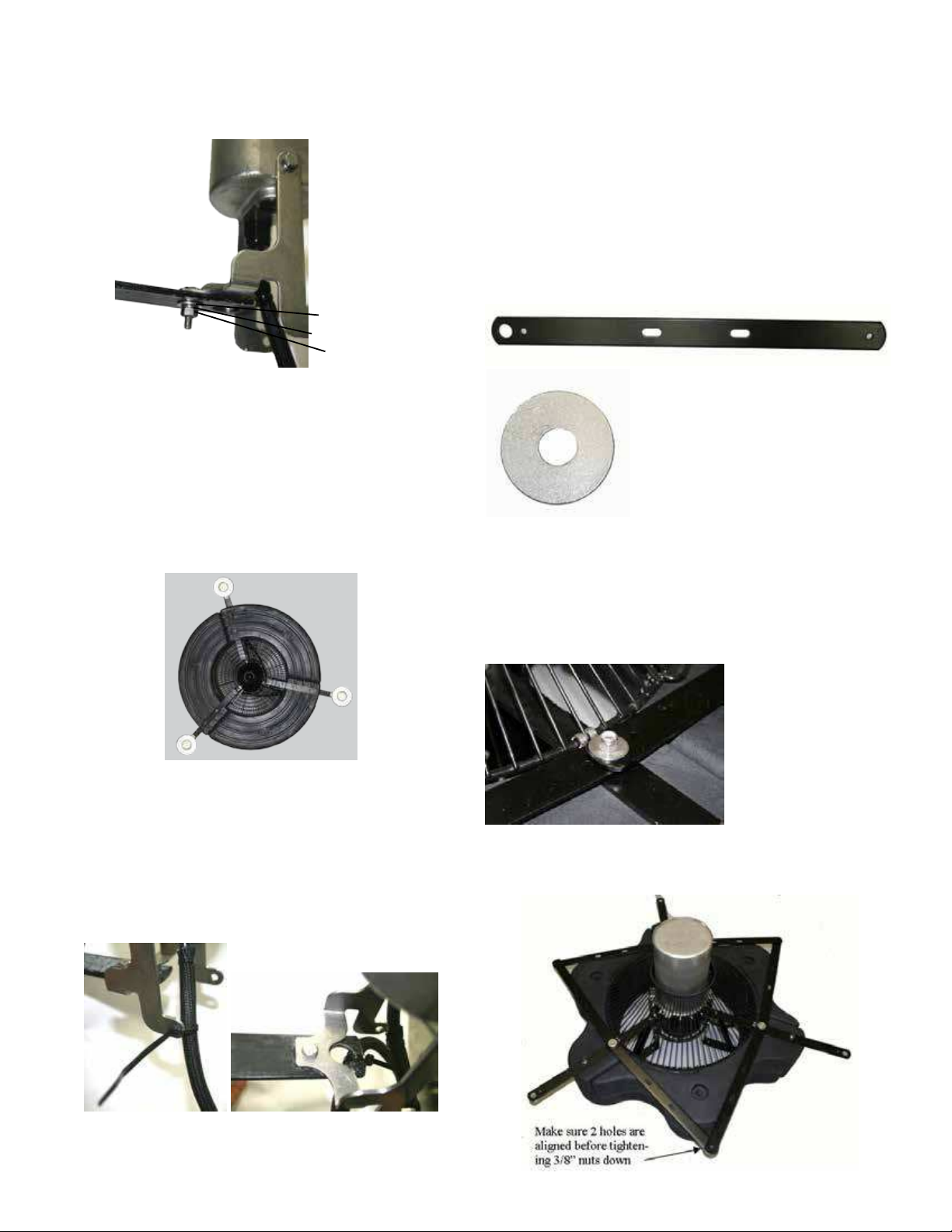
3. Follow the instruction on the previous page
(LED3S19 Assembly instructions) to mount the light
kit to the brackets.
Maintenance Recommendations
•
• Under No Circumstances should anyone enter the water
while a fountain is operating.
• Please keep the original box for maintenance shipping.
The following maintenance procedures can be utilized to
ensure many years of quality performance from your Kasco
Fountain and Light Kit and reduce the need for more costly
repair work.
PROPER INSTALLATION: Proper installation of Kasco
equipment will include a power source with ground fault
protection. For Fountain models, Kasco provided control
panels included with the unit have built-in ground fault pro-
tection. Ground fault interrupters are a safety feature that
can also alert you to electrical leaks in the equipment. If
you have repeat, consistent trips of the ground fault device,
the equipment should be disconnected and removed from
the water. The power cord should be inspected for dam-
age and you should contact your distributor, or call Kasco
Marine at 715-262-4488 for further instructions or email
OBSERVATION: Operating equipment should be observed
on a regular basis (daily, if possible) for any reduction or
variation in performance. If a change in performance is ob-
served, the equipment should be disconnected from power
and inspected.
freezing in the wintertime, the fountain and light kit should
be removed from the water to protect them from the expan-
sion pressure of the ice. In many areas, fountains will keep
some amount of ice open through the winter. However,
when the water is thrust into the air, it is exposed to the
colder air temperatures longer and can actually make ice
thicker on the pond/lake. Storage over winter is best in a
location that is out of the sun and cool, but above 32° F.
CLEANING: Fountains and light kits should be removed
from the water at least once per year (at the end of the
season in cold climates) to clean the exterior of the sys-
tem, especially the stainless steel motor housing (can) and
dissipate heat into the water and any algae, calcium, etc.
build-up will become an insulator that blocks heat trans-
fer. In warmer regions it is recommended that the motor
is removed and cleaned at least two to three times per year

7
Kasco Marine, Inc.
800 Deere Rd.
Prescott, WI 54021
Attn: Repairs
Note: Please contact Kasco to determine if the main power
cord needs to be returned to be considered for warranty.
The power cord may be needed to diagnose the failure.
Please include the Repair Form received from Kasco
Marine or your local distributor with the shipment. If no
Repair Form is available, include your name and physical
address for return delivery of the repaired Light Kit and
a daytime phone number and/or e-mail address for corre-
spondence regarding the warranty claim.
Any expedited shipping method for the return of the unit is
at the customer’s expense. Kasco Marine will return units
repaired under warranty at our expense via ground freight
Non-Warranty Repairs:
Most failed equipment can be repaired at substantially
lower costs than replacement with new. If your light kit
requires repair and is no longer covered under warranty,
please contact Kasco Marine for current repair pricing.
Please ship according to the instructions in the previous
section. Again, it is best to call ahead for a Return Autho-
rization Number and/or Repair Form so we know the repair
is coming.
All light kits that are rejected for repair will be destroyed
unless otherwise directed by the customer. If the customer
would like the Light Kit returned, it will be restored as
closely as possible to the condition in which it was received
and shipped at the customer’s expense for shipping and
handling charges.
Billing:
All non-warranty repairs will be returned to the customer
and billed C.O.D. unless otherwise directed. Kasco Marine
also accepts Visa and MasterCard credit card payments.
Kasco Marine will call for credit card information upon
completion of the estimate at the customer’s request.
All other warranty and repair inquiries should be directed
to Kasco Marine, Inc. at 715-262-4488 or

8
Troubleshooting Tips
Troubleshooting tips - light kit
Problem Possible Caus
e
Likely Remed
y
Power is off or disconnected
Ensure control panel is connected to the electrical circuit. Verify circuit breakers, timers, and/or
interlock switches are turned on and functional. Refer to your owners manual that was provided with
the fountian.
C-25 control panel:
The control panel has a photo eye on the left side of the enclosure exterior. This photo eye measures
ambient light. To activate, the photo eye must not measure any ambient light for at least several
minutes. Also, the C-25 timer must be turned on (fountain operating) to allow the light circuit to
energize. Covering the photo eye with black electrical tape will activate the photo eye for testing.
C-85, or C-95 control panel with GFCI outlet and photo eye control:
The control panel has a photo eye on the left side of the enclosure exterior. This photo eye measures
ambient light. To activate, the photo eye must not measure any ambient light for at least several
minutes. Also, the fountain timer must be turned on (fountain operating) to allow the light circuit to
energize. Covering the photo eye with black electrical tape will activate the photo eye for testing.
While the photo eye is covered, the GFCI outlet can be reset if tripped.
Timer not set properly
C-85, or C-95 control panel (and all 3phase fountain control panels) with terminal connections
and timer control for light kit:
The control panel has a second timer for controlling the lights (No photo eye). Ensure the light timer
is set to operate the lights. The timer has a built in Hand-Off-Auto swith. Ensure the switch is set
properly.
Ensure the fountain is turned on. The light timer will not energize the light kit unless the fountain
circuit is energized.
C-25 control panel:
Reset the GFCI. If the GFCI does not reset it could be a ground fault in the fountain wiring, or the light
kit wiring. Unplug both the fountain and light kit and reset the GFCI. If it resets, plug fountain then
light kit back in and see which one trips the GFCI. If the GFCI does not reset with both unplugged,
then the GFCI may be defective.
C-85, or C-95 control panel with GFCI outlet and photo eye control:
To reset the GFCI outlet the fountain timer must be turned on, and the photo eye must be activated.
(black electrical tape can be wrapped around the photo eye to activate it). Once these are on, the
GFCI reset button can be pressed. (unplug the light kit prior). Plug the light kit in and see if it
operates. If the GFCI trips again then the light kit may be damaged. If the GFCI does not reset (with
light kit unplugged) then it may be defective or the photo eye is not activated to send power to the
outlet.
C-85, or C-95 control panel with terminal connections and timer control for light kit:
For panels with a GFCB (ground fault circuit breaker) and timer controlled lights, simply reset the two
pole breaker. This will turn the fountain and light kit back on if the timers are set to on! If it trips again,
disconnect the light kit from the terminals and reset. WARNING! you must turn off power to the panel
before disconnecting any wiring from the terminals! If the breaker trips with the light kit
disconnected, then disconnect the fountain as well and reset. If the breaker continues to trip it may
be a defective GFCB. If the breaker resets, then reconnect the fountain then the light kit to see which
one trips the GFCB.
3phase fountain control panels:
3phase fountain panels have a ground fault sensing module that will trip if either the light kit or
fountain has a ground fault. To reset the module, simply press the reset button in the panel. This will
turn the fountain and light kit back on if the timers are set to on! If it trips again, disconnect the light
kit from the terminals and reset. WARNING! you must turn off power to the panel before
disconnecting any wiring from the terminals! If the GFI module trips with the light kit disconnected,
then disconnect the fountain as well and reset. If the GFI module continues to trip it may be a
defective module or an internal wiring issue with the panel. If the module resets, then reconnect the
fountain then the light kit to see which one trips the module.
Light work. However,
they are not as bright as
when first installed.
Dirty lenses
Turn of power to the control panel and disconnect power cords to the fountain and the light kit.
Bring the fountain to the shore and inspect the light lenses. Over time, algae growth and hard water
deposits on the lenses can block light output. Clean the lenses with a soft brush and the light should
be bright again.
Not dark enough for photo
eye to activate
Light kit is installed and
wired, but will not turn
on.
GFCI is tripped
The following is provided to help diagnose a probable source of trouble. It is a guideline only and may not show all causes for all problems. For additional
troubleshooting help contact your local distributor or visit www.kascomarine.com for additional help.
NOTE: you may need to refer to your owners manual that was provided with your fountain for additional control panel settings and adjustments.

9
ITEM NO . PA RT NUM BER DESC RIPTIO N Q TY.
1 451126 SC REW , 1/ 4-20x1/ 2" 2
2 840537 LO C K WA SHER, 1/ 4" 2
3 346065 BRAC KET, S.S. LED MO UNTING 1
4 346090 C A P, LENS, S-19 LED LIG HT 1
5 345559 LENS KIT, 4 C O LO RS 1
3
2
SERVIC E O R REPA IR.
MODEL LEDxS19-xxx
19 WATT LED LIGHT FIXTURE
REPLACEMENT PARTS
5
1
DO NOT ATTEMPT TO OPEN!
C O NTAC T KA SC O MA RINE FO R
INSTRUC TIO NS REG ARDING
4
Replacement Parts

10
800 Deere Rd.
Prescott, WI 54021
Phone: 715-262-4488 - Fax: 715-262-4487
www.KascoMarine.com [email protected]
Customer Repair Form
* Important Reminders *
•
• Address your Repair to Kasco Marine, Attn: Repairs (or to your Authorized Repair Center.
• Shipping to Kasco or an Authorized Repair Center is paid for by the customer.
•
• Do not ship the control box with the unit for repair, unless otherwise instructed.
Today’s Date:___________________
Customer Information
Name: _________________ Phone Number: _____________________
Address: __________________________ Alternate Number: ___________________
City: ____________________ Email Address: ______________________
State: _____________________
Zip Code: ______________________
Unit Information:
Model # (Ex. LED3S19): ____________________
Serial # (Ex. 2101LEDS3025)___________________
Date Purchased: ________________________
Purchased From: _________________________
Earliest Date of Problem: _______________________
Description of Problem:
Comments:

11

12
Registration Information
Fill in the information below and keep for your records.
Model # (Ex. LED3S19)_______________________________
Serial # (Ex. 2101LEDS3001)____________________________
Purchase Date:_____________________
Purchased From:___________________________________
Registration Date: ___________________________
Kasco Marine, Inc.
800 Deere Rd.
Prescott, WI 54021
Phone (715) 262-4488 • Fax (715) 262-4487
884050
This manual suits for next models
1
Table of contents
Other Kasco marine Floodlight manuals
Popular Floodlight manuals by other brands

Elation
Elation ARENA PAR ZOOM user manual

BOSS ILLUMINATION
BOSS ILLUMINATION SCORPIO II product manual

Cocoon
Cocoon HE200074 instruction manual

Conrad
Conrad 57 74 62 operating instructions

Home Zone Security
Home Zone Security ES00731V installation instructions

German Light Product
German Light Product impression Wash One instruction manual