3
CONTENTS
FOREWORD/IMPORTANT INSTRUCTIONS................................................................................ 2
GENERAL SAFETY NOTES...................................................................................................... 2
CONTENTS............................................................................................................................... 3
SAFETY INSTRUCTIONS........................................................................................................... 4
METER PROPERTIES/SCOPE OF SUPPLY ................................................................................ 4
SCOPE OF SUPPLY ................................................................................................................ 4
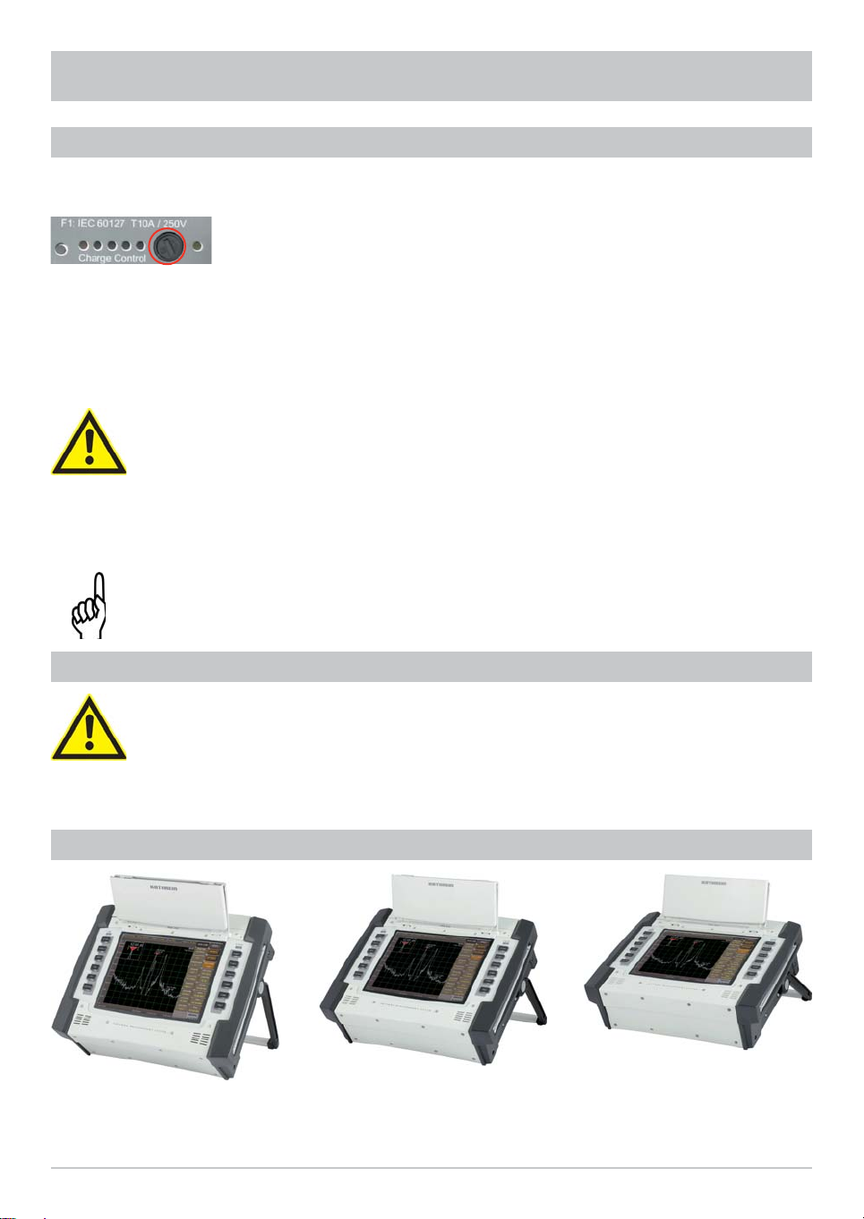
SET UP..................................................................................................................................... 5
INITIAL SET UP....................................................................................................................... 5
SETTING UP THE DEVICE....................................................................................................... 5
OPTIONS FOR SETTING UP.................................................................................................... 5
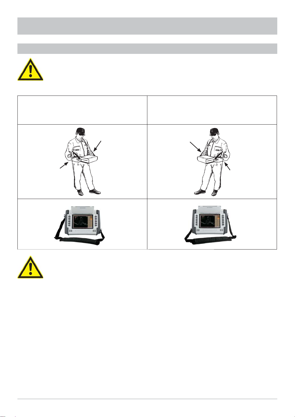
USING THE DEVICE ON THE STRAP....................................................................................... 6
BASIC INFORMATION ON OPERATION ..................................................................................... 7
THE HELP FUNCTION............................................................................................................. 7
CHANGING THE LANGUAGE FOR THE HELP FUNCTION .............................................................. 7
KEYBOARD OPERATION......................................................................................................... 7
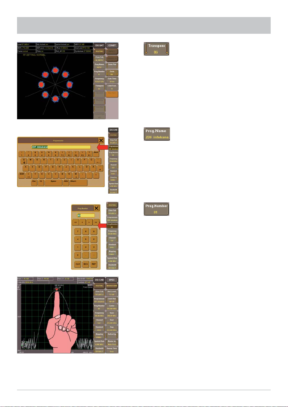
TOUCHSCREEN OPERATION.................................................................................................. 8
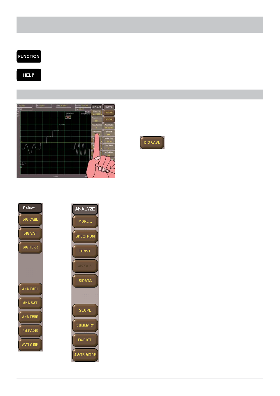
OPERATION............................................................................................................................. 11
SELECTION OF THE SIGNAL SOURCE AND THE MEASUREMENT.......................................... 11
SELECTION OF THE SIGNAL SOURCE ..................................................................................... 11
SELECTION OF THE CHANNELTO BE MEASURED.................................................................... 12
SELECTION OF THE MEASUREMENT...................................................................................... 12
OVERVIEW OF FUNCTIONS.................................................................................................... 14
TECHNICAL APPENDIX........................................................................................................... 16
DESIGN................................................................................................................................ 16
FUNCTIONS.......................................................................................................................... 16
VARIANTS............................................................................................................................. 16
MAINTENANCE....................................................................................................................... 22
DEVICE CALIBRATION.......................................................................................................... 22
OUTSIDE CLEANING............................................................................................................. 22
INTERIOR CLEANING............................................................................................................ 22
FUNCTION TEST................................................................................................................... 22
REQUIRED MEASURING EQUIPMENT................................................................................... 22
STORAGE............................................................................................................................. 22
SERVICE ................................................................................................................................ 23
CUSTOMER SERVICE........................................................................................................... 23
KATHREIN CUSTOMER HOTLINE.......................................................................................... 23