2
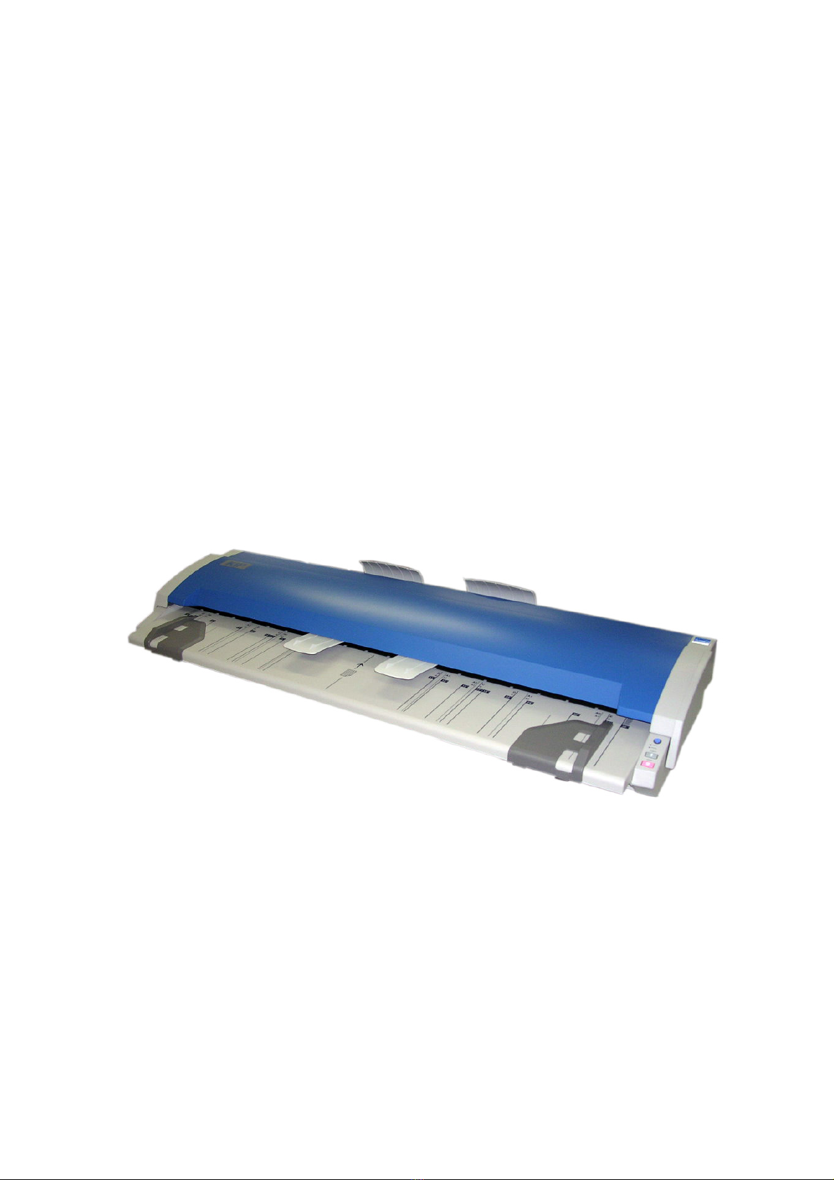
1 Installation Requirements
The following conditions have to be satisfied when installing the KIP 600.
1. Satisfy the following input power condition.
Voltage 100V to 240V
Current 1A or higher
Frequency 50 / 60Hz.
The KIP 600 can be supplied with any voltage between 100V to 240V. If the voltage is within
this range, please connect to the outlet simply. (No setting has to be changed.)
2. Make sure to connect the power plug to the outlet that is provided with the Ground Terminal.
FINLAND: Laite on liitettävä suojamaadoitus koskettimilla varustettuun pistorasiaan
NORWAY: Apparatet må tilkoples jordet stikkontakt
SWEDEN: Apparaten skall anslutas till jordat uttag
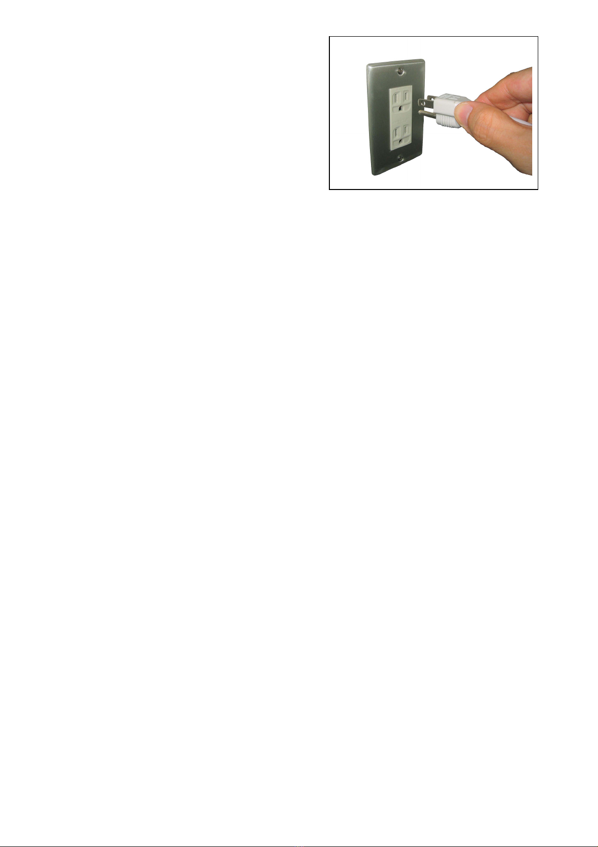
3. To completely disconnect the equipment from the power source, please draw the power plug
from the outlet.
The outlet must be easily accessible near the equipment.
4. The temperature must be within the range from 10 to 32 degrees centigrade, and the humidity
must be from 20% to 80%.
5. Prevent the equipment from fire, dust and direct sunlight.
If it is impossible to avoid the direct sunlight, please pull the curtain to intercept the sunlight.
6. The floor must be enough strong to withstand machine’s weight (About 24kg).
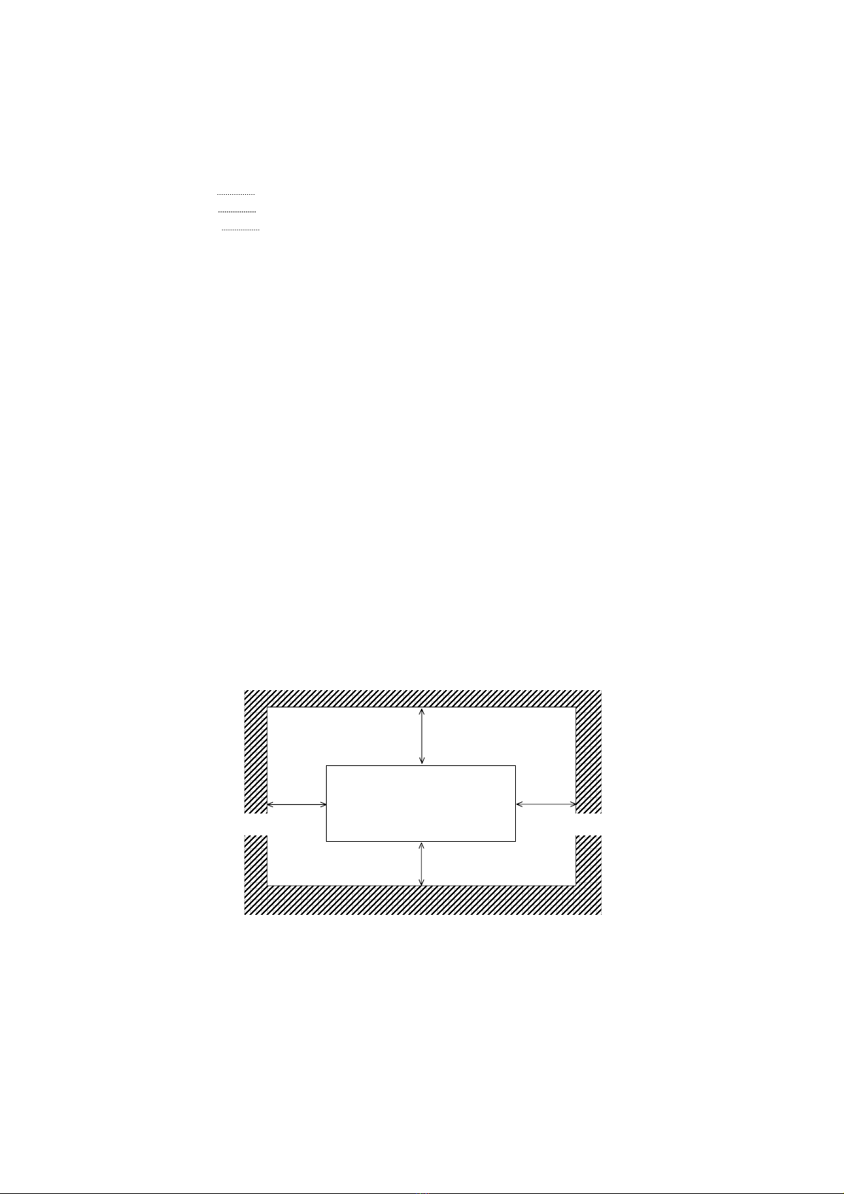
7. Keep enough space around the machine as follows.
(The following values are the least requirements. Please keep a wider space if possible.)
KIP 600
[Front]
[Rear]
300mm or wider
300mm or wider 300mm or wider
200mm or wider