Kay GPA-5000IR series User manual

GPA-500IR SERIES
INFRARED PORTABLE SOUND SYSTEM
INFRARED
Portable Sound System

GPA-500IR family products...................................................................................
GPA-500IR illustration...........................................................................................
GPA-500IR with tripod and wall brackets..............................................................
Infrared Sensor illustration....................................................................................
Master controls illustration.....................................................................................
UM-501 digital audio player illustration...........................................................
Infrared handheld microphone illustration.......................................................
External sensor illustration..........................................................................
Troubleshooting / Caution...................................................................................
Maintenance guidelines................................................................................
Specifications...............................................................................................
1
2
3
4
5
6 - 7
8 - 9
10 - 11
12
13 - 14
15 - 17
PREFACE
Thank you for the purchase of Infrared Portable Sound System GPA-500IR series.
Please take a look at this manual carefully before your first operation, to secure
the best performance and application.
INDEX

1
GPA-500IR FAMILY PRODUCTS
GPA-500IR1
One-channel
Infrared Portable Amplifier
GPA-500IR2
Dual-channel
Infrared Portable Amplifier
GPA-500IU1
One-channel
Infrared Portable Amplifier
with Audio Player Inbuilt
GPA-500IU2
Dual-channel
Infrared Portable Amplifier
with Audio Player Inbuilt

2
GPA-500IR ILLUSTRATION
4
3
2
1
5
6
7
8
9
10
11
13
12
GPA-500IR System Features
1.
2.
3.
4.
5.
6.
7.
Sensor power indicator
Dual-channel sensor module (IRS-10)
Infrared receiver module (IR-502)
5" Driver
F sockets for external sensor
Master controls
Battery door
8.
9.
10.
11.
12.
13.
Charging indicator
Power switch
DC input
Stand mount
One-channel infrared receiver
module (IR-501)
Digital audio player (UM-501)
Unscrew the battery
door Take out the battery Connect the new battery
with power lead
Red lead: Anode (+)
Black lead: Cathode (-)
Battery Replacement

3
GPA-500IR WITH TRIPOD AND WALL BRACKETS
1. 2. 3.
OPTION
Tripod and Wall Brackets
Matching with
universal microphone
stand
Matching with
tripod ST-35
Matching with
wall brackets SP-500
1. 2. 3.
D-2
SP-500
washer
D-2
ST-35
mic stand

4
INFRARED SENSOR ILLUSTRATION
1 2 3 4
1.
2.
3.
4.
CH.A: LED lights red when power is on; LED lights green when receiving signal
CH.B: LED lights green when receiving signal
AF: LED lights amber when sound outputs
Volume control and power switch (sensor)
1 2 3 54
1 2
1.
2.
Infrared sensor indicator: LED lights red when in receipt of infrared signal
Infrared sensor
INFRARED RECEIVER ILLUSTRATION
OPTION
IR-501 One-channel Infrared Receiver Module
IR-502 Dual-channel Infrared Receiver Module
1.
2.
3.
4.
5.
CH.A volume control and CH.A power on
CH.A: LED lights red when power is on; LED lights green when receiving signal
AF: LED lights amber when sound comes out
CH.B: LED lights red when power is on; LED lights green when receiving signal
CH.B volume control and CH.B power on
IRS-10 Infrared Sensor Module

5
MASTER CONTROLS ILLUSTRATION
Master Controls
1 2 3 4 5 67
1.
2.
3.
4.
5.
6.
7.
MASTER: control audio volume of infrared receiver, wired microphone and
auxiliary input
TONE: bass and treble control
AUX IN: auxiliary input control
MIC: wired microphone volume control
MIC IN: wired microphone input (Ø 6.3mm)
AUX OUT (Ø 3.5mm): connect with an extra amplifier
AUX IN (Ø 3.5mm): connect with an external audio source, ex. iPod or laptop

6
UM-501 DIGITAL AUDIO PLAYER ILLUSTRATON
1
8 9 10 11 12
2 3 4 5 6 7
UM-501
Remote Control
1.
2.
3.
4.
5.
6.
7.
8.
9.
10.
11.
12.
13.
POWER: turn on the UM-501 player
LCD: to show the folder number / track number /
time duration / music source / playing mode /
status displayed
REPEAT: set the track repeatedly
PREV / : back to the previous track / folder
NEXT / : reverse to the next track / folder
STOP / : stop playing music
PLAY / : play / pause
SD slot: insert SD memory card
USB port: connect with the USB source
VOL- / : volume down
VOL+ / : volume up
FLODER / : to select the different folder from the current
playing music source
MUTE / : sound mute
FLODER
VOL+
VOL-
13
UM-501 Digital Audio Player
OPTION

7
UM-501 DIGITAL AUDIO PLAYER ILLUSTRATON
1.
2.
3.
4.
5.
To connect your USB music source with UM-501, GPA-500IU starts playing mp3
file automatically. The LCD shows the current folder / track number / playing
duration.
When both of USB and SD card are connected with UM-501, USB source is
the priority for UM-501 to play. When disconnecting both of USB and SD card,
UM-501P stops playing music and records the last playing folder / track number;
to insert the same USB or SD card again, UM-501 starts playing from the previous
recorded track.
To disconnect the USB or SD card after pressing STOP (1), UM-501 does not
record the last playing folder / track number; to insert the same USB or SD card
again, UM-501 starts playing the USB or SD cards from the beginning.
To take out the SD card, please push the card gently in advance, and then the
card should eject automatically; to pull out SD card appropriately would cause
the damage on SD card and also the music player.
Press button FOLDER (12) in advance to active the folder selection function.
To select different folder by pressing NEXT (5), PREV. (4),and then press PLAY
(7) to complete the folder selection.
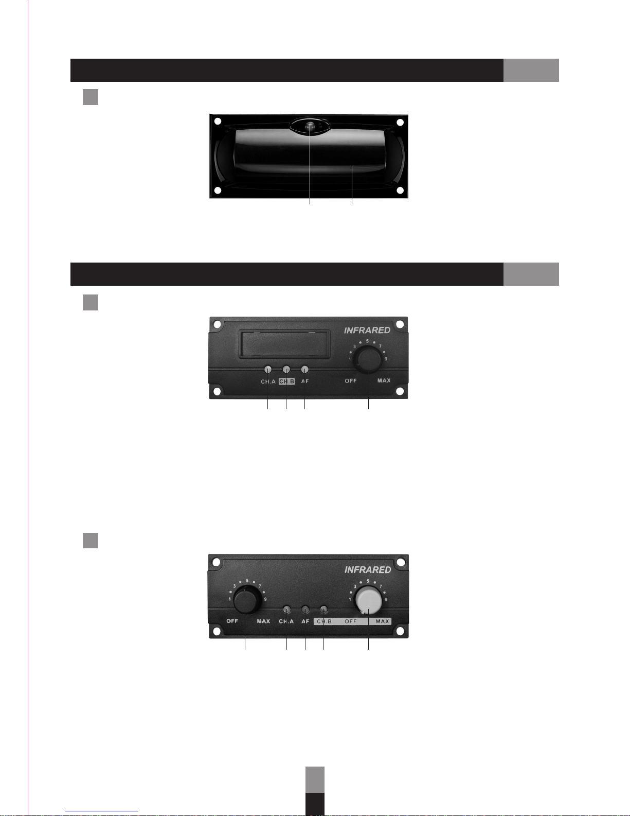
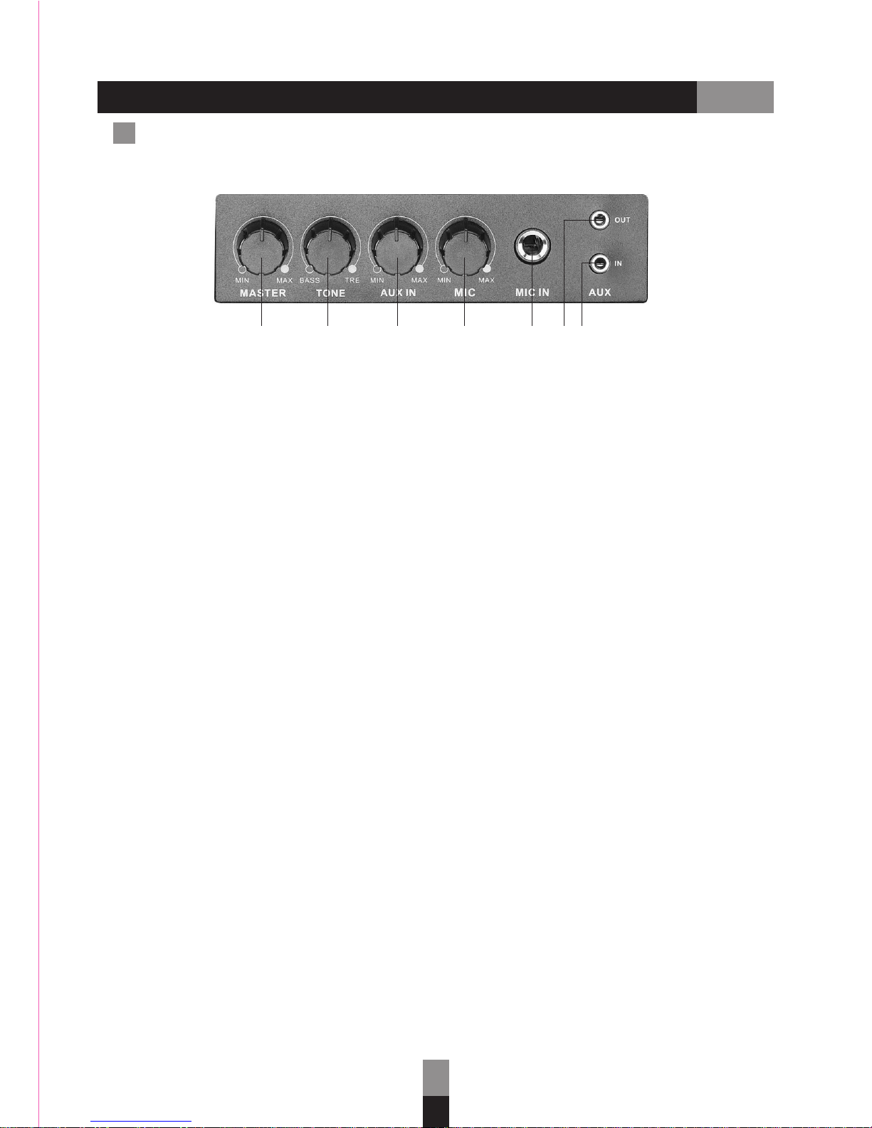
Operation Indication of UM-501
OPTION

8
Pull the battery door to the direction of the mesh head.
Place 2 pcs AA 1.2V (Ni-MH 2500 mAh) batteries into the
battery case; batteries should be placed by the correct
direction of (+) and (-) .
After correct battery installation, close and lock the battery
door well.
8.
9.
10.
11.
12.
13.
Talk/Mute switch
A/B channel switch
Battery case
Battery door
Hi/Low output power switch
Charging contact
INFRARED HANDHELD MICROPHONE ILLUSTRATION
EJ-501TI Infrared Handheld Microphone
Battery installation of EJ-501TI
Mesh head
Top emitter
Main body
Power indicator
Power switch button
Bottom emitter
3.5mm Mic/Aux input
1.
2.
3.
4.
5.
6.
7.
118 9 10 12
12 3 64 5
13
7

9
FG
INFRARED HANDHELD MICROPHONE ILLUSTRATION
Please avoid your hand covering the top emitter and bottom emitter
1.
Select a channel by A/B Channel Switch (9)
*
*
A CH -> Channel A (2.3 MHz)
B CH -> Channel B (2.8 MHz)
2.
Select output power by HI/LOW Selector (12)
*
*
HI -> Distance can reach to 20 M; power consumption around 300 mA
LOW -> Distance can reach to 15 M; power consumption around 200 mA
4.
Switch the button (8) to the Talk status when you intend to amplifier your speach;
switch the button (8) to the Mute status when you are temperately not using the
microphone.
Insufficient power influences the signal transmission. We
recommend you using the capacity 2500 mAh rechargeable
batteries and dual-slot charger HDC-502 as the best
solution.
6.
5.
Press the power switch button (5) for 4~5 seconds to
turn the device off.
HDC-502
3.
After battery installation and close the battery door, press the power switch button
(5) for 1 second, and then the power indicator (4) lights up to show the device
being on.
*
*Lights green: power sufficient
Lights red: power insufficient; please prepare new batteries or recharging
procedure
CAUTION !
Only Ni-MH rechargeable batteries are allowed to be charged. It may cause
leakage or explosion when charging un-rechargeable batteries.
Please take out batteries if the unit isn’t in use for a long time to avoid battery
leakage.
Operation Indication of EJ-501TI
Correctly hand EJ-501TI

10
IRS-20 External Sensor
1 2 3 4 5 6
1.
2.
3.
Sensor power indicator
Infrared sensor
Screws for angle adjustment
4.
5.
6.
F socket for extension cable
Screws for wall fixed
Extension cable to connect with GPA-500IR
Single Reception Range
15m
150º
15m
80º
External Sensor Installation
2
1
Screwed the four corners
to fix on the wall or ceiling Connect the external cable
with F socket clockwise Anticlockwise direction
to unscrew and adjust
your preferred angle;
clockwise to screw
tightly and fix the position
2
1
EXTERNAL SENSOR ILLUSTATION
OPTION

15 M
15 M
15 M
15 M
15 M
15 M
Allocation in a Bigger Classroom
GPA-500IR
Infrared Portable
Amplifier
IRS-20
External Sensor
EJ-501TI
Infrared Handheld
Microphone
11
15 M
Allocation in a Middle-size Classroom
IRS-20
External Sensor
IRS-20
External Sensor
EJ-501TI
Infrared Handheld
Microphone
GPA-500IR
Infrared Portable Amplifier
EXTERNAL SENSOR ILLUSTATION
OPTION

12
TROUBLESHOOTING
Check the batterry with sufficient power and in a correct position.
No Power ON Indication
Check the Infrared Portable Amplifier and Infrared Handhold Microphone are at
the same channel.
Check the volume of Infrared Portable Amplfier is on.
Check the Infrared Handhold Microphone is switched to the "Talk" status.
No Sound Outputs
1.
2.
3.
Avoid rainfall or humid circumstance which may cause the unit broken or electric
shock.
Avoid the unit to be stroke and dropped.
Do NOT use the unorigianl power supply.
CAUTION

13
MAINTENANCE GUIDELINES
Do NOT put the unit in the sunshine for a long time, or any other hot, humid
environments and places with flame. Stay away from any occasions which the
above might occur. Choose cooler places to store the unit.
Avoid Heat, Humidity
After unpacking the unit for the first time, please charge the unit for about 8 hours.
This is absolutely necessary as the built-in rechargeable batteries might have been
discharged naturally due to long shipment and storage time, even though it has
been fully charged in the factory prior to shipment. To secure a longer life for
batteries, please DO execute this IMPORTANT process.
Charge BEFORE You Start Using for the Fist Time
Ensure batteries are fully charged BEFORE you store it for a long period. To
maintain a longer battery life and better performance, make sure you charge the
batteries regularly every month.
Charge Fully
This unit has DOD (depth of discharge) protection design. After the Power Switch
LED flashes red which means there isn't enough electricity (when operating via
the batteries' power), this unit will turn off automatically to secure battery from
deep-discharging damage. At this moment please immediately recharge your
unit, do not continue operation.
Notice : when you need to use the unit again after a long period of stock, make
suer you charge it fully for at least 8 hours BEFORE any operation.
Notice : please also charge this unit every time after operation to gain a longer
battery life.

14
This unit has protection circuit against overcharge. After the batteries finish
charging, the unit will stop charging automatically. You can still operate during
charging.
NAINTENANCE GUIDELINES
Make sure the substitute battery is with same specifications. Using incorrect batteries
may lead to explosion or malfunction
Replacing Batteries
Before operation, ensure battery contacts are clean and free of corrosion. If corrosion
occurs, please replace it or contact your place of purchase if service is required.
Transmitter's Battery Terminals
Remove the batteries in the transmitters if for a long
while you are not going to use it.

15
SPECIFICSTIONS
GPA-500IR Infrared Portable Amplifier
850 nm
2 (CH.A: 2.3 MHz; CH.B: 2.8 MHz)
TRF (Tuned Radio Frequency)
50 kHz
32.768 kHz
110 dB
< 1%
70 Hz ~ 10 kHz (receiver)
-10ºC ~ +50ºC
F type
20 meters (Hi) / 15 meters (Low)
Wave length
Channel
Receiver system
Max deviation
Tone
Dynamic range
Distortion
Frequency response
Operation temperature
Input connector
Reception range
30 Watts (RMS) @ 4Ω
5" full range
> 70 dB
IR-501 or IR-502
Mic (6.3mm), Aux (3.5mm)
Aux (3.5mm)
Master, Tone, Mic, Aux
50Hz ~ 15kHz
100 ~ 240 VAC / 18 VDC, 2.7 A
12 V, 2.9 A (Lead-Acid)
3 ~ 4 hours
4 ~ 6 hours
260 x 210 x 290 (mm)
4.10 kg
Output power
Driver
S/N ratio
Receiver module
Inputs (stereo)
Outputs (stereo)
Controls
Frequency response
Power supply
Battery
Operation time
Charging time
Dimensions
(D x W x H)
Weight
IR-501 / IR-502 Infrared Receiver Module
IR-501 IR-502
1 2
2 (CH.A : 2.3 MHz; CH.B : 2.8 MHz)
12 VDC
200 mA
128 x 88 x 37 (mm)
100 g
Module
Volume control knob
Channels
Power supply
Current consumption
Dimensions (D x W x H)
Weight

16
EJ-501TI Infrared Handheld Transmitter
850 nm
Green -> sufficient power
Red -> low power
CH.A: 2.3 MHz
CH.B: 2.8 MHz
Talk, Mute
FM
Hi: 20 meters (face to face)
Low: 15 meters (face to face)
two AA Ni-MH rechargeable batteries (2500 mAh) or Alkaline
8 hours (2500 mAh, power set "Hi")
11 hours (2500 mAh, power set "Low")
200 mV (RMS)
10k Ω
> 70 dB
< 1%
70 Hz ~ 10 kHz (± 3 dB)
-10ºC ~ +50ºC Max deviation: ± 50 kHz
38 x 198 (mm)
140 g (including batteries)
Wave length
Battery power capacity
Carrier frequency range
Controls
Modulation
Output power
Battery
Battery life
Aux input level
Aux input impedance
S/N ratio
Distortion
Frequency response
Operation temperature
Dimensions (Dia x L)
Weight
SPECIFICATIONS
IRS-10 / IRS-20 Infrared Sensor
IRS-10
Module
Power supply
Current consumption
Dimensions (D x W x H)
Weight
Extended cable
Reception angle
Reception range
12 VDC
25 mA
143 x 88 x 38 mm
85 g
---
24 VDC
15 mA
133 x 103 x 48 mm
250 g
10 meters
80º (Vertical) / 150º (Horizontal)
15 meters
IRS-20

17
UM-501 Digital Audio Player
20 Hz ~ 20 kHz
DC 12V
LCD screen
1 V ± 2 dB
MPEG layer 3 audio decoder
> 60 dB
< 1 %
> 5 meters
PLAY, STOP, REPEAT, NEXT, PREV,
VOLUME, FOLDER
USB port, SD/MMC card insert
Frequency response
Power supply
Display status
Output level
Decoder format
S/N ratio
T.H.D.
Remote range
Controls
Interface
SPECIFICATIONS

4F, No.11, Lane 125, Sec 1, Kuo Kwang Rd., Ta Li City,
Taichung Hsien, Taiwan
Tel:+886-4-2407-1617 Fax:+886-4-2407-1609
E-mail:[email protected]
www.okayo.com
Rev. 01
Table of contents