KDF Cascom SE User manual

Instruction Manual
Before using the KDF Cascom SE, please read the manual thoroughly and understand
the capabilities and proper usage for this machine.
Technical advice and tips regarding casting are covered in the separate " Casting Manual ".
Please keep these manuals in an easily accessible location for your future reference.
W1014600-8

Contents■
P1■Safety Precautions
P4■Standard Accessories
P5■Descriptions of Component Parts
Main Parts and Descriptions P5●
P6■Preparations before Use
Power Requirement P6●
Location & Environment P6●
Piping of Cooling Water, Vacuum Pump & Argon Gas P6●
P7■Power On
P7■Operation Panel
Display & Lamp P7●
Buttons P7●
P8■Casting Parameters
Parameters and how to set P8●
P9■Melting and Casting
Crucible Installation P9●
Ring Installation P10●
Chamber Lid Locking P10●
Melting and Casting P11●
Other Operations during Melting and Casting P12●
P12■Other Operations
Chamber Position Adjustment P12●
Air/Argon Switch Knob P12◎
P13■Periodic Machine Cleaning
Muffle Cleaning P13●
Drain Filter Check P14●
Dust Proof Filter Cleaning P14●
Compressed Air Filter Check P14●
P15■Vacuum Filter and the Exhaust Filter Check
Vacuum Filter Check P15●
Exhaust Filter Check P15●
Chamber Lid Seal Ring P16●
P16■Caution & Warning
Cautions P16●
Warnings P17●
P18■Optional Items
P19■Consumables
P20■Specifications

-1-
Safety Precautions■
We recommend you to follow these instruments for proper use of the unit.
The safety precautions contained herein and the accompanying icons are provided for the safe
use of this machine and to prevent injuries and loss on material resources.
Please read them carefully prior to your actual machine operation. It is recommended that use of
this unit should not be attempted by anyone who is not well informed of he precautions necessary
for machine operation.
Reference pages of the related topics in this manual are illustrated with arrow marks (i.e. P12)→
Failure to follow or ignorance of the directions may cause
severe injury or death.
Failure to follow or ignorance of the directions may cause
injuries or damages to material properties.
Examples of Precaution Icons
This mark requires a user to pay attention to the caution mark as shown
inside or around it. The illustration on the left means to exercise caution
for shock hazard.
This mark means prohibited actions as shown inside or around it.
The illustration on the left means “Do not disassemble.
This mark means forced action and directions to follow as shown inside
or around it. The illustration on the left means “Unplug out of power outlet”.
WARNING
CAUTION

-2-
Keep the unit away from a person with a pacemaker.
Prohibited The magnetic field may cause a malfunction of a pacemaker.
Keep away from a person with a pacemaker.
In the event when there is smoke, abnormal odors or sounds,
Unplug unplug immediately and contact the dealer for repairs.
Continued use may cause electric shock or fire.
We recommend you not to attempt repairs yourself.
In the event when water or debris enters the machine, unplug
Unplug immediately and contact the dealer for advice.
Continued use may cause electric shock or fire.
In the event when the machine is dropped or the furnace frame is
Unplug dented, unplug immediately and contact the dealer for advice.
Continued use may cause electric shock or fire.
When the water leaking warning (Warning 01 & 02) is displayed, unplug
Unplug and stop using immediately. Continued use may cause electric shock.
Do not remove the panels or parts uninstructed or modify them in any
Do Not manner. Some of the parts inside contain high voltage and contact with
Disassemble them may cause fire or electric shock. We recommend you to
contact the dealer for repairs or machine maintenance.
Connect a grounded outlet. Improper connection may cause electric
Ground shock.
Connection
Plug to the power outlet of the designated voltage described in the main
Not Designated specifications. Use of any other voltage may cause fire or shock.
Volt. Prohibited
The machine can melt alloys with an opened lid. In case of melting alloy
Strictly Required with an opened lid, use protective glasses, a heat resistant glove, and
surgical mask.
Keep the unit away from other equipment and walls.
Leave minimum of 20cm of space around the unit as well as 1m of space above theProhibited ・
unit. If not, conduct fire prevention.
WARNING

-3-
Do not use or place anything flammable near the machine.
Prohibited Fire or skin burns may result.
Do not place the machine on an unstable base to prevent falling or
Prohibited damage to the unit. This may cause injury.
When you unplug the power cord from the power outlet, do not pull the
Prohibited cord. If the cord is damaged, it may cause fire or shock.
Always remove by handling the plug.
Do not place heavy items or place machine on the power cord and
Prohibited make sure that the cord is not pulled too tightly and not damaged.
This may cause fire or electric shock.
This machine is for dental casting. We do not recommend you to use
Prohibited the machine for any other purposes.
Please use KDF genuine products for consuming parts, option parts
Prohibited and / or parts for repairing.
Otherwise, it may cause the machine failure or trouble.
Pay attention when the chamber inverts. It could tug your tie, scarf,
Caution stole, etc.
Check prior to Check the machine for signs of parts damage prior to use and make
use sure the unit is in normal state. Contact the dealer for advice when you
find anything abnormal.
Plug the main power cord completely into the power outlet. The plug
Strictly Required may heat up and cause fire or burns if not entirely plugged in.
In addition, if the metal part of plug is touched while the plug is not
fully plugged in, electric shock may result.
Unplug the main power cord from the power outlet when the machine is
Unplug not in use for a long period of time.
In case of periodic machine maintenance, unplug the power cord from
Unplug the power outlet. Do not handle the plug with wet hands.
This may cause electric shock.
Do not handle the machine with wet hands as this may cause electric
Wet Handing shock.
Prohibited
CAUTION

-4-
Standard Accessories■
When you unpack the machine, we recommend you to make sure that the
following standard accessories are included. In addition, please check the
machine for any damage or dent on the unit surface. Contact the dealer if there
is any damage on the unit.
Normal tweezers for several uses.Small Tweezers 1 pc
Stand for crucibles, tweezers and melting alloy outlet.Crucible Stand 1 pc
Ceramic Crucible(3pcs), Carbon Crucible S(1pc), Melting Alloy Outlet (3pcs)Crucible Box 1 pc
Reserve of Vacuum Filter Element.Vacuum Filter Element 1 pc
Blue Piping Tube for
Used to connect compressed air to chiller and argon gas to the unit.Air & Argon Gas (5m) 1 pc
Operation manual with precautions for safe and proper uses of the unit.Instruction Manual 1 booklet
Instruction and tips on casting techniques for the unit.Casting Manual 1 booklet

-5-
Descriptions of Component Parts■
Main Parts and Descriptions●
() ()Front View Back View
Operation Panel Panel to operate a casting process.
Pressure Gauge Indicates pressure inside of the muffle chamber.
Lock Arm Used to lock the chamber lid and seal the muffle chamber.
Power Switch with 20A breaker. In case of eddy current, shut it down immediately.
Dust Proof Filter Used to prevent dust from entering the unit.
Muffle Chamber Used to house furnace muffle to heat up and melt casting alloys.
Chamber Lid Handle Used to manually open and close the chamber lid.
Note) Be gentle when you open and close the chamber lid. Quickly repeated movement will cause damage
to the unit.
View Glass Used to protect eyes when checking melting alloy.
Vacuum Filter Used to prevent dust in the chamber from entering the unit.
Eyebolt Used to prevent the unit from falling down. Tie down the unit.
Air/Argon Switch Knob Manual switch knob to choose between pressurized air or argon gas in applying
pressure for casting.
Compressed Air Filter Used to prevent rust, dust, moisture etc. out of compressor from entering the unit.
Periodic cleaning is recommended.
Drain Cock Cock to drain the moisture in the internal air tank.
Exhaust Filter This is the exhaust filter of vacuum unit.
Operation panel
Air/Argon Switch Knob
CHILLER OUTLET CHILLER
SIGNAL
ARGON
0.5-1.0MPa WATER A WATER B
AIR IN
0.5-1.0MPa
DRAIN COCK
View Glass
Chamber Lid
Handle
Muffle Chamber
Dust Proof Filter
Power Switch
Lock Arm
Pressure Gauge
Drain Cock
Vacuum Filter
Eyebolt
Eyebolt
Compressed Air Filter
Exhaust Filter
EXHAUST
FILTER

-6-
Precautions before use■
Power Requirement●
The unit requires a power outlet with independently wired, 220-240V single-phase, 20A and grounding.
Note) Do not use a 2 pin plug adaptor and break a grounding pin of power cord. They may cause electric shock.
Location & Environment●
Set up the unit on the center of a flat stable table.
Keep the unit away from walls and other equipment.
Note) Leave minimum of 20cm of space around the unit as well as 1m of space above the unit.
Do not place anything flammable near the unit. If not, conduct fire prevention.
Piping of Cooling Water, Vacuum Pump & Argon Gas●
Connect cooling water and pressurized air to the unit as shown in figure below.
If necessary, connect argon gas to the unit.
Note) When the external chiller HPC-20 is not used for water supply, please keep cooling water temperature under 60 .℃
Improper temperature may cause malfunction of the unit.
.Note) The unit will not work without the proper connection of WATER A and WATER B
Note) Cut the blue piping tube for air & argon gas (5m) to proper length.
Note) Connect the white piping tube completely until the red line. Improper piping may cause water leaking.
Note) Connect CHILLER SIGNAL terminal completely with screws.
Note) Keep the hose length short to decrease the flow resistance within hose to a minimum.
Note) Keep the air pressure between 0.5 and 1.0MPa.
Note) Keep the argon gas pressure between 0.5 and 1.0MPa.
Note) Place the hose in a secure location where it will not get stepped on or tripped over.
The installation is finished.
CHILLER OUTLET CHILLER
SIGNAL
ARGON
0.7-0.8MPa WATER A WATER B
DRAIN COCK
Cut blue piping tube for use.
External compressed air 0.5~1.0Mpa
Power Cord
Cut blue piping tube for use.
Argon Gas 0.7~0.8Mpa
Connection for
optional chiller
(HPC-20)
Cooling water input
Connection for optional chiller (HPC-20)
or water connection part (DW-60)
Cooling water exhaust
Connection for optional chiller (HPC-20)
or water connection part (DW-60)
AIR IN
0.5-1.0MPa
EXHAUST
FILTER

-7-
Power On■
After installation is complete, turn the power on.
When using an optional chiller (HPC-20) and turning on the power for the power on, wait for 10 minutes
until water circulates completely. When warning “Chiller Water Current Abnormal” is displayed, turn
off and on. In the case of chiller abnormal warning due to improper piping of chiller or insufficient amount
of water, turn off the unit, check the connection, add water, and turn the unit back on again.
When using direct connection of water and error is displayed due to uncirculated or low flow, check
the water supply status.
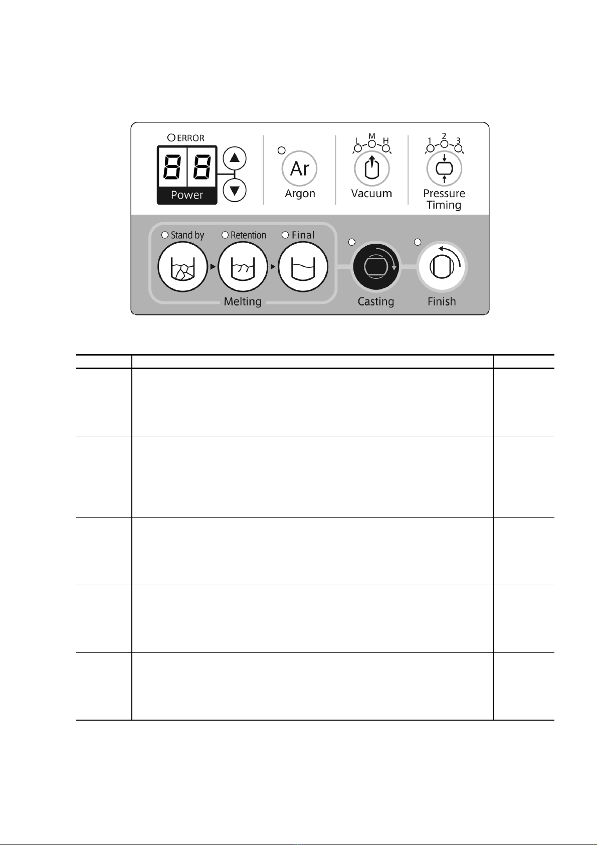
Operation Panel■
Display & Lamp●
ERROR Lamp When the unit is abnormal, the lamp will illuminate and error number will be・」「
displayed on 2-digit display.
Power Display High frequency power is displayed between 0 and 99%. Elapsed time is displayed・」「
during cooling of casting or when the unit is abnormal, error number is displayed.
Ar Lamp The lamp illuminates when argon gas is injected.・」「
L M H Lamp Vacuum level is displayed. The lamp will blink during vacuum operation.・、、」「
1 2 3 Lamp Pressure Timing is displayed. The lamp will blink during pressurization.・、、」「
Stand by Lamp The lamp will illuminate during Stand by Melting operation.・」「
Retention Lamp The lamp will illuminate during Retention Melting operation.・」「
Final Lamp The lamp will illuminate during Final Melting operation.・」「
Casting Lamp The lamp will illuminate when casting is available and blink during pressurization.・」「
Finish Lamp The lamp will illuminate during cooling.・」「
Buttons●
Change the high frequency power in increments of 5%.・ △、▽」「
Ar Is ON/OFF button to inject argon gas.・」「
Vacuum Change vacuum level.・」「
Pressure Timing Change pressure timing.・」「
Stand by ON/OFF button of Stand by Melting operation.・」「
Retention ON/OFF button of Retention Melting operation.Retention Melting・」「
Final ON/OFF button of Final Melting operation.・」「
Casting Pressthebuttontocastwithchamberinvertingandpressure.・」「
Finish After cooling time is finished, press the button to complete casting.・」「

-8-
Casting Parameters■
Parameters and how to set●
Content Description Default
Vaccum Vacuum level during melting and casting. The range: L ow M iddle H igh M() ( ) ()、、
L: Silver M: Non Precious H: Gold、、
The level changes in the order corresponding to L M H L.→→→
Pressure Set pressure timing from chamber inverting to pressure application. 1
Timing The range: 1 2 3、、
()、()、( )1: Fast Cobalt 0.5s 2: Middle Nickel 0.7s 3: Slow Gold, Silver 0.9s
The timing changes in the order corresponding to 1 2 3 1.→→→
Stand by Set standby melting power. The value range: 0~99%. 99
This operation is to mass the melting alloy before casting.※
Can change in increment of 5% with buttons during Stand-by operation.△▽
Retention Set retention melting power. The value range: 0~99%. 40
This operation is to hold temperature, not to cool the melting alloy when setting a casting ring.※
Can change in increment of 5% with buttons during Retention operation.△▽
Final Set final melting power. The value range: 0~99%. 70
This operation is to reach the casting temperature.※
Can change in increment of 5% with buttons during Final operation.△▽

-9-
Melting and Casting■
Note) Never touch hot objects such as crucibles, melting alloy outlet and casting rings with bare hands.
Do not put bare hands inside of the hot muffle chamber. This may cause skin burn.
Crucible Installation●
Set a crucible and melting alloy outlet as shown in the figures below.
Note) Dedicate a crucible and melting alloy outlet for each alloy.
Note) Do not forget to set the melting alloy outlet. If it is not set, the splashing of melting alloy inside the chamber muffle may cause
malfunctions.
Carbon Crucible Ceramic Crucible
Note) Put a carbon crucible in a ceramic crucible not melting alloy.
Ceramic Crucible
Carbon Crucible
Melting alloy outlet Melting alloy outlet
Ceramic Crucible

-10-
Ring Installation●
Tilt the lever to your right to unlock the casting Set a casting ring against the melting alloy
ring stand. Insert the provided tweezers to the outlet without gap between melting alloy and
hole of the lever and move up and down in casting ring
Note) When taking hot casting rings out, use a heataccordance with size of casting ring.
resistant glove and tongs to prevent skin burn.
There are labels of 3, 4, 6, 8, 9 on the backside of the casting ring stand.
Nearly Equal; 3: dia.34 4: dia.46 6: dia.60 8: dia.80 9: dia.90、、、、
Note) Do not touch the casting ring stand. This may cause skin burn.
Chamber Lid Locking●
Place a casting ring and close the chamber lid.
Note) Open and close the chamber lid gently to prevent malfunction.
Move up and put the lever on the ditch. Move down the lever to turn on the lock switch
and ready to cast.

-11-
Melting and Casting for Precious Metal●
Check the condition of ceramic crucible (cracks, damage) and set the ceramic crucible and melting alloy①
outlet properly.
Note) Do not forget to use the melting alloy outlet to prevent machine malfunction.
Put alloy inside of the crucible. Line up alloy ingots in order to prevent crucible breakage due to alloy②
heat expansion. Especially, in case of using used alloy, take care of alloy heat expansion.
Close and lock the chamber lid.③
Press the “Standby” button to vacuum and increase the temperature inside of the chamber.④
Check the melting condition visually from the window of lid and wait until the melting alloy become mass.
Note) Use a shaded protective glass to protect your eyes in case of high temperature.
After the melting alloy become mass, press the “Retention” button to hold the temperature.⑤
Unlock the chamber lid with this condition and vacuum will be automatically released wait 5 seconds to⑥ (
open the door . After the release of vacuum, place a burned-out casting ring. If the button is not at the)
center, adjust the space so that the casting ring is set properly and fit the melting alloy outlet.
Note) In case sprue center is not at the center of investment ring, place sprue center to upward to utilize the casting chamber
space and close the casting chamber lid.
Lock the chamber lid and press the “Final” button so that “Casting” lamp will illuminate and “Casting”⑦
button will be usable.
If the chamber lid is not locked completely, cannot use the “Casting” button.※
After checking the alloy melting condition, press the “Casting” button to invert the muffle chamber⑧
automatically.
”Casting” lamp blinks during cooling and elapsed time of cooling is displayed in increment of 10※
seconds on the “Power” display. . means 1 minute 40 seconds.
After required cooling time is finished, press the “Finish” button to release pressure and revert the⑨
muffle chamber to the original position.
If it takes 10 minutes, pressure is released and revert the muffle chamber to the original position※
automatically.
Open the chamber lid and remove the casing ring.⑩

-12-
Melting and Casting for Semi and Non-Precious (Metal that contains Palladium for more than 30%).●
Process until the is same as Melting and Casting Precious metal.②
Place a casting ring inside the muffle chamber.③
Close and lock the muffle chamber.④
Press the Ar button to repeat twice to create a vacuum and inject an argon gas with 0.03MPa pressure⑤[]
inside the muffle chamber (takes approx. 70 sec). The pressure gauge must be at 0.03 before .⑥
After Argon substitution is completed, press the Final button to melt the alloy.⑥[]
When the casting timing nearly comes, press the Ar button again to vacuum in the muffle chamber.⑦[]
Back to of “Melting and Casting Precious Metal” .⑧
Other Operations■
Chamber Position Adjustment●
Muffle rotation and its position could slightly move after many years of usage.
In this case, adjust the muffle rotation and its position by the following.
Keep pressing the button and press the “Finish” button during the standby mode after power on. L, M▲
and H lamp of “Vacuum”, lamps of “Stand by”, “Retention”, “Final” and “Casting” illuminate and “Finish”
lamp blinks.
1. Lock the chamber lid and press the “Argon” button so that its lamp illuminates and the muffle chamber
inverts.
2. Press the “ ”” ” buttons to adjust the casting position (inverting position). When the rotation is too▲▼
far, subtract the casting position value.
3. Press the “Pressure Timing” button so that the lamps of L, M and H go out and lamps of 1, 2 and 3
illuminate.
4. Press the “ ”” ” buttons to adjust the melting position (original position) in the same way as the▲▼
casting position.
5. Press the “Vacuum” button to adjust the casting chamber position again. After some adjustments of the
casting chamber position and melting chamber position, press the “Vacuum” button to finish the adjustment.
If you do not press the “Finish” button, the adjustment will not be saved.※
Note) If the unit continues the operation 50 times, “ERROR” lamp blinks and the unit stops inverting. Press the “Argon” button to※
adjust their positions again.
Air/Argon Switch Knob◎
The knob is equipped at right side of the unit. You can choose air pressure or argon gas pressure.
Argon gas pressure is useful to minimize oxidation of melting alloy.
In case of using argon gas pressure, use a regulator to set pressure between 0.5 and 0.9MPa.※
Note) Perform the casting operation without melting of the alloy to exhaust gas because it will be mixed in the first pressure after※
the pressure type is switched.

-13-
Periodic Machine Cleaning■
In order to maintain the capacity of this unit further longer the following periodic cleanings prior to use are
recommended.
Note) When you perform machine maintenance, make sure that the unit is turned off and the muffle heat is as low as room temperature
to prevent the cause of skin burn and electric shock.
Muffle Cleaning●
When the chamber turns upside down for casting operation, metal debris, etc. in the muffle may result in
miscasting. We recommend you to use the dust collector provided referring to the following recommendations.
Figure 1. Open the chamber lid and lift the knob ( ). Move the knob in the direction of to unlock.①②
Figure 2. Lift the tab to remove the casting ring stand.
Figure 3. Take out the dust collector on the bottom to clean the dust. In reverse order, place the dust collector
and the casting ring stand back to its original position.
Figure 1
Figure 2 Figure 3
②
①
Dust Collector

-14-
Drain Filter Check●
See the drain window equipped on the left of the unit to check the moisture in the air tank.
Loosen the drain cock equipped on the backside of the unit to drain the moisture in the air tank.
Loosen the drain cock gently to prevent the moisture from shooting. Use a waste pan to catch the moisture.
Ifyouusetheunitwithmoisturecollectedovertheallowable level, the moisture will come in contact with
inside of the unit and cause machine malfunction.
Dust Proof Filter Cleaning●
If you use the unit with the clogged filter, the cooling fan will not work properly and cause overheating of
the parts and machine malfunction. Remove the filter that is located on the bottom of the unit to clean the
dust with an air gun.
Compressed Air Filter Check●
(← )Press the button at the bottom of compressed air filter marked on the right
to drain the moisture gathered inside the compressed air filter. We recommend you
to drain the moisture each time before using the unit, regardless of the amount of
moisture collected. If you use the unit with the moisture collected over the allowable
level, the moisture will come in contact inside the unit to cause machine malfunction
when you apply pressure.
Drain Window
Drain Cock
Waste Pan
(Left View)

-15-
Vacuum Filter and the Exhaust Filter Check■
In case, vacuum speed is not well, it may be caused
by dirty vacuum filter and/or dirty exhaust filter.
So, cleaning up the filter or replacing the filter is required.
Refer the following process.
Vacuum Filter Check●
Make sure the pressure gauge is at 0MPa.①
Slide the baffle in the direction of arrow to unlock.②
Rotate the cover over 180 degree counterclockwise.③
Remove the case from the cover.④
Clean inside of the filter with an air gun or replace⑤
the element.
Insert and rotate the cover 180 degree clockwise until it⑥
stops.
Turn the baffle back to the lock position and check to⑦
lock the cover completely.
Exhaust Filter Check●
Check the pressure gauge is at 0MPa.①
Remove the filter and clean it up inside by air-gun or replace with new one.②
Vacuum Filter
Exhaust Filter

-16-
Chamber Lid Seal Ring●
The dirt on the seal ring may not allow you to
reach sufficient vacuum level or vacuum may
leak during pressure application. Use a clean
wet cloth to wipe the dirt on the seal ring
before casting operation.
Caution & Warning■
When the following messages are displayed, address according to the message. Contact our service
team if there is no improvement. The following errors may sometimes be displayed in cases when there
is extreme interference. Please turn off the unit and on again to see if the error code persists.
Note If the errors are not displayed after the unit is turn off and on again, there may be deletion or modification of casting)
programs and defaults sets.
The followings are considered to be possible source of interference.
Lighting strikes, Arc casting machine in the vicinity, Radio transmitter in the vicinity,・・ ・
Induction motor in the vicinity.・
Cautions●
When the following cautions are displayed, you can skip cautions to use the unit. However we recommend※
you to maintain and check the unit when errors/cautions are displayed to prevent further malfunctions.
1. Time over of induction
High frequency current carrying time reaches the limited time.
The limited time is 5 minutes. Press any button to return to normal display.
2. Abnormal cooling fan filter
The cooling fan does not work properly. Clean the filter at the bottom of the unit.
When there is no improvement, replacement of the fan may be required.
Press any button to return to normal display. However we recommend you to maintain the unit promptly.
3. Water Overheating
When using the optional chiller, chiller water temperature is overheating.
Wait for 10 minutes to use the unit. When it is often displayed than before, clean the chiller filter.
If room temperature is high, there is a high possibility of this caution.※
Seal Ring

-17-
Warnings●
When the “ERROR” lamp illuminates, you cannot use the unit. Repair it according to provided solutions.※
If there is no improvement, contact our support team.
Cause: The optional chiller is abnormal. Cause: Water is leaking in the unit.No.00 No.01
Solution: Check the connection of outlet and signal Solution: Stop using the unit immediately. Contact
terminals. our support team for repair.
Cause: Water is leaking in the optional chiller. Cause: Chiller water is below required amount.No.02 No.03
Solution: Stop using the optional chiller. Contact our Solution: Check the amount of the chiller water and
support team for repair. add coolant or water if necessary.
The poor connection of the signal terminals may The poor connection of the signal terminals may※※
cause this warning. cause this warning.
Cause: Chiller water is not flowing. Cause: The muffle chamber does not invert to theNo.04 No.05
casting position.
Solution: Check the bend of piping of optional chiller Solution: Check if any objects interfere with
or tap water or the flowing of tap water. inverting the chamber.
The poor connection of the signal terminals may※
cause this warning.
Cause: The muffle chamber does not invert to the Cause: The overcurrent of high frequency power.No.06 No.10
melting position.
Solution: Check if any objects interfere with Solution: The noise may occur this warning. If this
inverting the chamber. warning is often displayed, contact our support team
for repair.
Cause: The protective circuit of high frequency Cause: High frequency is not output.No.11 No.12
power is operated.
Solution: The noise may occur this warning. If this Solution: High frequency power may malfunction.
warning is often displayed, contact our support team Contact our support team.
for repair.
Cause: It cannot measure power frequency. Cause: The power supply voltage is out of range.No.14 No.15
Solution: High frequency power may malfunction. Solution: The unit can work with single-phase,
Contact our support team. 220-240V and 20A. Check the power supply voltage
and allowable current.
Cause: The memory data is damaged. Cause: The control board is abnormal.No.16 No.17
No.21
Solution: The noise may cause data damage or Solution: If this warning is often displayed, contact
change memory. Check the memory. our support team for repair.
Cause: The high frequency power board isNo.18
abnormal.
Solution: If this warning is often displayed, contact
our support team for repair.

-18-
Optional Items■
The water connection part (DW-60) or optional chiller (HPC-20) is strictly required to use the unit.
The expanded chiller (HPC-40) is available when the HPC-20 is connected.
Water connection part Type DW-60●:
This part is used to connect tap water to the unit to cool with tap water.
Optional chiller Type HPC-20●:
This chiller is used when you do not connect tap water for cooling.
Water can be stored and cooled in internal tank.
The connection of the expanded chiller (HPC-40) is available.
Expanded chiller Type HPC-40●:
Expanded Chiller (HPC-40) for continuous castings.
Note) The optional chiller is required to connect this chiller.
Table of contents
Popular Dental Equipment manuals by other brands

Ivoclar Vivadent
Ivoclar Vivadent Bluephase Style 20i Instructions for use

EMS
EMS FT-188 Operation instructions

Carestream DENTAL
Carestream DENTAL CS 3800 User and installation guide

DENTSPLY
DENTSPLY WAXPENCIL PRO 9995337 Owner's/operator's manual

Air Techniques
Air Techniques ProVecta 3D Prime operating instructions

Vaniman
Vaniman StoneVac II manual

Dabi Atlante
Dabi Atlante Syncrus G3 owner's manual

DENTSPLY
DENTSPLY CAVITRON JET AIR Series DIRECTIONS FOR USE and INFECTION CONTROL PROCEDURES

Durr
Durr 2134-510-50E quick start guide

Sirona
Sirona ORTHOPHOS XG 5 installation instructions

CMS Dental
CMS Dental FlashMax P3 Module Replacement Instructions

KaVo
KaVo SONICflex 2003 Instructions for use