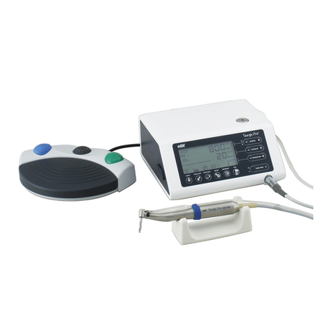
NSK Primado2 User manual

OM-SE0021E 005

1
English
Class
Degree of Risk
DANGER
Hazard that could result in personal death or serious injury if the safety instructions are not
correctly followed.
WARNING Hazard that could result in serious injury or damage to the device if the safety instructions
are not correctly followed.
CAUTION
Hazard that could result in light or moderate injury or damage to the device if the safety
instructions are not correctly followed.
NOTICE General product specification information highlighted to avoid product malfunction and
performance reduction.
This product is a surgical system used for bone operations (removal, cutting, perforation and formation), or cutting implants. We recommend
that prior to use, you carefully read this Operation Manual regarding "Precaution for Handling and Operation", "Connection method",
"Operation method", "Check before Operation” and "Periodical Maintenance Check" so that you can continue using the Attachments in the
future. In addition, keep this Operation Manual in a place where a user can refer to it at any given time.
* In this operation manual Bur, Drill, Blade and Disk are collectively called Cutting Accessory(ies).
* For reprocessing of the Control Unit, Foot Control, Motor and Attachment or operation method of the Attachment, refer to each manual (see
Table-1).
Table-1
Operation Manual Title Operation Manual No.
Primado2 REPROCESSING MANUAL OM-SZ0911MA
Primado2 OPERATION MANUAL Attachments OM-SH0913MA
●Read these precautions carefully and use only as intended or instructed.
●Safety instructions are intended to avoid potential hazards that could result in personal injury or damage to the device. Safety instructions
are classified as follows in accordance with the seriousness of the risk.
Precautions for Handling and Operation
CONTENTS
Precautions for Handling and Operation ……………………………………………………………………… 1
1. Component Names ……………………………………………………………………………………… 4
2. Part Names ……………………………………………………………………………………………… 5
3. How to Connect Each Component ………………………………………………………………………… 12
4. Check before Operation …………………………………………………………………………………… 16
5. Operation ………………………………………………………………………………………………… 16
6. Option Set Up …………………………………………………………………………………………… 20
7. Fuse Replacement ………………………………………………………………………………………… 25
8. Periodical Maintenance Checks …………………………………………………………………………… 25
9. Reprocessing …………………………………………………………………………………………… 25
10. Error Codes ……………………………………………………………………………………………… 26
11. Troubleshooting ………………………………………………………………………………………… 29
12. Specifications …………………………………………………………………………………………… 31
13. Disposing of Product …………………………………………………………………………………… 32
14. Warranty ………………………………………………………………………………………………… 32
15. Symbols ………………………………………………………………………………………………… 32
16. EMC Information ………………………………………………………………………………………… 33
English

2
Before use, read carefully the Operation Manual of the Motor and the Attachments.
User and Intended Purpose
Primado2 is intended for the following applications:
Cutting, drilling, removal, and shaping of bones and implants in the fields of Neuro, Spine, Orthopedic, ENT, Oral maxillofacial, and Plastic
and reconstructive surgery.
DANGER
●Do not use this system in a room where there is danger of explosion or in the vicinity of flammable substances. It is especially important
not to use this system on a patient to whom a flammable anesthetic agent (dinitrogen monoxide) has been administered.
●Should a short circuit occur inside this product, an electric shock or fire may result if the product is not connected to properly grounded
electric supply.
●After use, turn off the Power Switch. If the unit is not being used for a prolonged period, disconnect the Power Cord Plug from the outlet.
Otherwise dust or deteriorated insulation might cause electric shock or fire.
●Never disassemble or modify the product. Personal injury, electric shock or fire may result.
WARNING
●This is a medical system; do not allow anybody to use it other than surgeons who are familiar with the procedures. Use this system in
accordance with its intended purpose and method of use described in this Operation Manual.
●Do not subject this unit to strong impacts, such as dropping it on the floor. Personal injury, abnormal heating and fire may result caused
by the internal damage.
●This product may be affected when used in rooms with electromagnetic interference and portable or mobile RF communication
equipment. Do not use this product around any equipment that generates electromagnetic waves such as an ultrasonic generator and
electrical scalpel. When using equipment generating electromagnetic waves, turn off the power to the Control Unit.
●Do not directly spray detergent/liquid on the LCD Touch Panel of the Control Unit when cleaning the Control Unit. Otherwise, it may cause
failure.
●Except for the Foot Control, this system is not designed to be water-proof. Handle the Control Unit and Motor with care so that they will
not be exposed to water or sterile water (saline solution). An electric shock may result due to a short circuit.
●The Irrigation Tube and Cutting Accessory are for single use only. Do not reuse or reprocess it. If you reuse or reprocess it, the following
risks may occur:
– Infection.
– Personal injury due to damaged Cutting Accessory.
– System defect due to damaged/deformed Cutting Accessory.
●Irrigate appropriately while cutting in order to prevent necrosis of bones and tissues.
●After purchase or repair of the Motor (optional), be sure to clean and sterilize the Motor before use (refer to OM-SZ0911MA Primado2
REPROCESSING MANUAL).
●After purchase or repair of the Attachment (optional), be sure to clean, lubricate and sterilize the Attachment before use (refer to OM-
SZ0911MA Primado2 REPROCESSING MANUAL).
●Do not lubricate the Motor. It may result in an abnormal heating and failure.
CAUTION
●When operating the product, always consider the safety of the patient.
●Users shall be responsible for any judgement that relates to the application of this product to a patient.
●Users are responsible for the operational control, maintenance and continual inspection of this System.
●Be sure to read this Operation Manual and the Operation Manuals for "Primado2 Motor" and each Attachment in order to become
completely familiar with the function of each part before use.
●Connect the product to an electrical outlet for medical use or a properly grounded outlet.
●Be sure to perform inspection by operating the product with the Motor, Attachment and Cutting Accessory mounted before use (see “4
Check before Operation”). If any abnormal condition is detected, stop using the product and contact your Authorized NSK Dealer.
●Use these products after performing “4 Check before Operation”. When you feel an abnormality such as vibration, overheating or
noise while in use, immediately stop using them and perform inspection (see “11 Troubleshooting”). If the issue does not improve after
troubleshooting, contact your Authorized NSK Dealer.
●Do not bend or kink the Irrigation Tube while the Irrigation Pump is operating. Damage or disconnection of the Irrigation Tube may result.
●Wear Personal Protective Equipment (PPE) during operation.
●It is recommended that a spare product be kept on hand in case of a breakdown during surgery.
●When the Control Unit and Foot Control are stained with blood, turn off the power and wipe the stains off using a lint-free cloth moistened
with neutral detergent for medical use. Then, remove the detergent using a lint-free cloth moistened with distilled, deionized or
demineralized water.
3
English
CAUTION
●If chemicals, solutions or sterilizing liquid is left on the surface of the Control Unit and/or Foot Control, wipe it away immediately. If it is
left, it may lead to discoloration, deformation, rust and/or corrosion.
●Do not use the following fluids to wipe or clean the product: strong/super acid water, strong acid/alkaline chemicals, chlorine-containing
solutions, and solvents such as benzine or thinner.
●Do not disconnect the Motor Cord from the Motor. It may cause failure.
●Dispose of the used Irrigation Tube and Cutting Accessories as medical waste (see “13 Disposing of Product”).
●Connect or disconnect the cords or Attachments only after turning off the Power Switch. If the Power Switch is ON, an unintentional
movement may occur, which could result in injury to users.
●This product needs special precautions regarding EMC and needs to be installed and put into service according to the EMC information.
●The use of accessories, Motors and Attachments other than those specified, with the exception of accessories, Motors and Attachments
sold by the manufacturer of this product as replacement parts for internal components, may result in increased EMISSIONS or decreased
IMMUNITY of this product.
●This product should not be used adjacent to or stacked with other equipment. If adjacent or stacked use is necessary, observe this
product and other equipment in order to verify a normal operation prior to use.
●Regarding the operation time of the Motor, follow specification table in step “12. Specifications”. Continuous use of the Motor for a
prolonged period might cause overheating, which can cause an accident.
●This device is for indoor use only.
●Perform regular function and maintenance checks for the devices and parts (see “8 Periodical Maintenance Checks").
●If the product is not used for a long period of time, check if it functions correctly and safely before use.
●The temperature at the tip of the Attachment may reach up to 60°C depending on the environment.
●Check the correct connection of the following before use:
– Connection of the Motor Cord Plug and Foot Control Plug to the Control Unit.
– Connection of the Power Cord Plug to the Control Unit.
– Connection of the Power Cord Plug to the outlet.
●Only use the Irrigation Tube (Order Code: Y1003915) recommended by NSK. Otherwise, it may cause failure.
●Disconnect the Power Cord Plug, Motor Cord Plug and Foot Control Plug from the Control Unit when the product is not used. If excessive
impact is applied, such as hitting the connections without disconnecting them, failure of the Control Unit, Power Cord Plug, Motor Cord
Plug or Foot Control Plug may occur.
●Please report any serious incident that may occur in connection with this device and its accessories to the manufacturer as well as to
your national authority.
NOTICE
●After use, turn OFF the Power Switch. If the unit is not being used for a prolonged period, disconnect the Power Plug from the outlet. If the
unit is left plugged in and unattended for too long dust or deteriorated insulation might cause electric shock or fire.
●The user shall be responsible for maintenance and operation.
●Only use irrigation tubes recommended by NSK.

4
13)13)6)8)9)11)
7)12)10)
1)
2)
3)
4)
5)
No. Model Name of Component
1P200-CU-120
P200-CU-230
Primado2 Control Unit (120V/230V)
2Power Cord
3Irrigation Pole
4FC-74 Primado2 Multi Foot Control
5FC-73 Primado2 Single Foot Control
6P200-HMH Primado2 High Torque Motor
7P200-HMH-HS Primado2 High Torque Motor/HS
8P200-SMH-S Primado2 Slim Motor Short
9P200-SMH Primado2 Slim Motor
10 P200-SMH-HS Primado2 Slim Motor/HS
11 P200-BMH Primado2 Micro Bone Saw Motor
12 P200-BMH-HS Primado2 Micro Bone Saw Motor/HS
13 P200-WPD Primado2 Wire Pin Driver
These components are sold
separately, according to the
client’s specific needs.
1Component Names

5
English
2)
3)
5)
4)
1)
8)
9)
6)
7)
11)
13)
12)
10)
14)
1)
2)
4)
3)
5)
1)
2)
5)
2-1 Control Unit
Front Side of the Control Unit
1) Front Panel
2) Motor Connector A
3) Motor Connector B
4) LCD Touch Panel
5) Foot Control Connector
Right-hand Side of the Control Unit
6) Irrigation Pump
7) Guide Parts
8) Roller
9) Knob
Back Side of the Control Unit
10) Irrigation Pole Stand
11) Inlet Box
12) Power Switch
13) Fuse Box
Bottom Side of the Control Unit
14) Rubber Pads
2-2 Foot Control
Multi Foot Control
1) Foot Control Guard
2) Foot Control Button (Sliver)
3) Foot Control Button (Blue)
4) Foot Control Button (Green)
5) Pedal
Single Foot Control
2Part Names

6
2)
1) 3)
OFF
ON
4)
2)
3)
1) 4)
5)
2-3 Motor
P200-HMH, P200-SMH-S, P200-SMH, P200-BMH
P200-HMH-HS, P200-SMH-HS, P200-BMH-HS (Motor with Hand Contol)
1) Hand Switch* 2) Adjustable Lever*
3) Safety Lock* 4) Motor Cord Plug *Motor with Hand Control only.
P200-WPD
1) Trigger (Upper) (A) 2) Safety Lock 3) Trigger (Lower) (B)
4) Mounting/Removal Button 5) Motor Cord Plug
2-4 LCD Touch Panel: Operation Key
HOME screen
Main Panel
Sub Panel Mini Panel
●Whenever the icon is touched, the HOME screen appears, regardless of the current screen.
NOTICE

7
English
Icon DescriptionsName
HOME Screen
Main PanelSub Panel
Mini
Panel
Selects the Motor which is connected to Motor
Connector A.
If the Motor is not connected, “Disconnection” is
displayed.
Selects the Motor which is connected to Motor
Connector B.
If the Motor is not connected, “Disconnection” is
displayed.
Rotational speed can be adjusted by the Track
Bar and UP/DOWN Button.
The irrigation volume can be adjusted by the
Track Bar and UP/DOWN Button.
Irrigation is OFF by default. Irrigation is turned
ON by touching the button.
The rotational speed or irrigation volume can be
adjusted by moving the Track Bar to the left or
right.
Increases the rotational speed or irrigation
volume.
Decreases the rotational speed or irrigation
volume.
Changes the Rotation Mode of the Motor
connected to Motor A or B between Forward,
Reverse and Oscillate (P200-WPD only).
Shows that the Motor is rotating.
Whether the Irrigation Mode at ON or OFF, as
long as the Priming Button is kept pushed, the
irrigation volume is at 100% capacity.
Displays the function set up by the individual
buttons of the Foot Control Panel. If the Foot
Control is not connected, only is displayed.
Default setting: OFF. The Foot Control is turned
ON by pressing the button (see Figure above).
Displays the “Option Set Up” screen.
Motor Select Button A
Motor Select Button B
Speed Adjustment Area
Irrrigation Volume
Adjustment Area
Irrigation ON/OFF Button
Track Bar
UP Button
DOWN Button
Rotation Mode Select Button
“Rotating” display
Priming Button
Foot Control Panel
Foot Control ON/OFF Button
Option Set Up Button
2-5 Buttons & Icons

8
Icon DescriptionsName
Option Set Up ScreenControl Unit Set Up ScreenLanguage Set Up ScreenLanguage Set Up Confirmation Screen
Main PanelMain PanelMain PanelMain Panel Mini
Panel Sub
Panel
Displays the “Control Unit Set Up” screen.
Displays the “Motor Set Up” screen.
Displays the “Attachment Set Up” screen.
Displays “Foot Control Set Up” screen.
Displays previous screen.
Displays the HOME screen regardless of the
current screen.
By using the Track Bar and the UP/DOWN Button,
the brightness of the back light can be adjusted.
By using the Track Bar and the UP/DOWN Button,
the volume can be adjusted.
Displays the “Language Set Up” screen.
Shows the version of the hardware and software
of the Control Unit.
The language in which message alerts are to be
displayed.
The language selected in the Language Set Up
screen is set as the main language.
Cancels the language selected in the Language
Set Up screen.
Control Unit Set Up Button
Motor Set Up Button
Attachment Set Up Button
Foot Control Set Up Button
Back Button
HOME Button
Background Brightness
Adjustment Area
Volume Adjustment Area
Language Set Up Button
Information Button
Language Select Button
(English)
Language Select Button
(German)
Language Select Button
(French)
Language Select Button
(Spanish)
Language Select Button
(Italian)
Language Select Button
(Japanese)
“Yes” Button
English / German
French / Spanish / Italian
Japanese
“No” Button
English / Italian / Spanish
German / French
Japanese

9
English
Icon DescriptionsName
Motor Set Up ScreenAttachment Set Up Screen
Main PanelMain Panel
The acceleration time for the Motor to reach its
maximum rotational speed can be adjusted by
the UP/DOWN Button (10%~100%).
The braking time for the Motor to stop can be
adjusted by the UP/DOWN Button (10%~100%).
The torque of the Motor can be adjusted by the
UP/DOWN Button (30%~100%).
The Oscillating Turns can be adjusted by the
UP/DOWN Button (1~5) (P200-WPD only).
Returns the settings back to the original factory
setting made before delivery.
Changes the connection of the Motor between
Motor Connector A and B.
Indicates the rotational speed suited for the
Constant Speed Handpiece.
Indicates the rotational speed suited for the
Perforator Handpiece.
Indicates the rotational speed suited for the High
Speed Handpiece.
Indicates the rotational speed suited for the
Super Slim Handpiece.
Indicates the rotational speed suited for the 4:1
Speed-Reduction Contra Angle Handpiece.
Indicates the rotational speed suited for the 16:1
Speed-Reduction Contra Angle Handpiece.
Indicates the rotational speed suited for the 64:1
Speed-Reduction Contra Angle Handpiece.
Indicates the rotational speed suited for the
Constant Speed Attachment.
Indicates the rotational speed suited for the Bone
Saw Attachment.
Indicates the rotational speed suited for the
Reamer Attachment..
Acceleration Area
Brake Area
Torque Area
Oscillating Turns Area
Factory Default Button
Motor Select Button
Attachment Select Button
(Direct Drive)
Attachment Select Button
(Perforator)
Attachment Select Button
(High Speed)
Attachment Select Button
(Super Slim)
Attachment Select Button
(Contra 4:1)
Attachment Select Button
(Contra 16:1)
Attachment Select Button
(Contra 64:1)
Attachment Select Button
(Drill)
Attachment Select Button
(Bone Saw)
Attachment Select Button
(Reamer)

10
Icon DescriptionsName
Foot Control Set Up ScreenError Code Display Screen
Main PanelSub Panel
Mini
Panel
Displays the “Foot Control Set Up” screen.
Turns ON/OFF the operation of the Foot Control
by the Foot Control. When turned OFF, the
operation of the Foot Control becomes
unavailable.
Sets up the Motor connected to Motor Connector
A or B so that it can be switched over to another
Connector by the Foot Control.
Sets up the rotational speed of the Motor
connected to Motor Connector A or B so that it
can be switched over to another speed (30%→
Default, Value→100%) by the Foot Control.
Sets up the Rotation Mode of the Motor
connected to Motor Connector A or B so that it
can be switched over to another by the Foot
Control.
Sets up the Irrigation so that it can be turned
ON/OFF by the Foot Control.
Makes 100% irrigation available as long as this
button is pressed.
Sets the status as no function.
Highlights the Function Button currently used.
When an error has occurred simultaneously, a
blinking light announces the error. Touch the
Error Code Button to display the error code for
that error.
When an error has occurred in the Motor, this
indicates which Connector is connected to the
Motor.
Closes the Error display.
Foot Control Button
(Blue) (Only for the Multi
Foot Control)
Foot Control Button
(Silver)
Foot Control Button
(Green) (Only for the Multi
Foot Control)
Foot Control Pedal
ON/OFF Select
Motor Select
Speed Select
Rotation Mode Select
Irrigation ON/OFF Select
Flush
Disable
“Foot Control Button”
Display
(Only for the Multiple Model)
Error Code Button
Motor
Close Button

11
English
HOME Screen Main Panel
Sub Panel
Speed Adjustment
Priming
Motor Switch
Background Brightness
Adjustment
Volume Adjustment
Language Set Up
Information
Acceleration
Adjustment
Brake Adjustment
Torque Adjustment
Oscillating Turns
Adjustment
P200-HMH
P200-SMH
P200-BMH Bone Saw
P200-WPD Drill
Bone Saw
Reamer
French
German
English
Spanish
Italian
Japanese
Direct Drive
Perforator
High Speed
Direct Drive
Perforator
Super Slim
Contra 4:1 Contra 16:1
Contra 64:1
Super Slim
Control Unit
Set Up
Attachment Set Up
Foot Control Set Up
Option Set UpMini Panel
Foot Control
Function Selection
(Multi)
Foot Control
Function Selection
(Single)
Foot Control
Button (Silver)
Foot Control
Button (Silver)
Foot Control
Button (Blue)
Foot Control
Button (Green)
Irrigation ON/OFF
Switch
Disable
Flush
Rotational Speed
Switch
Foot Control
Operation
ON/OFF Switch
Rotation Mode
Switch
Rotation Mode
Switch
Irrigation Volume
Adjustment
Motor Switch
Motor Set Up
2-6 Flow Chart of the LCD Touch Panel

12
Fig. 1
Fig. 2
Fig. 3
3-1 Connection of the Power Cord
1) Connect the Power Cord into the end into the Inlet Box located at the back of the Control
Unit.
2) Plug the Power Cord to the medical-use outlet.
3-2 Connection of the Foot Control
By matching the mark on the Foot Control Plug and the mark on the Foot Control
Connector at the front of the Control Unit, plug the Foot Control into the Connector all the way
until you hear a clicking sound.
To disconnect the Foot Control, hold the Foot Control Plug and pull it out with a straight
movement.
●Do not remove the Power Cord or Motor Cord by holding the cord portion or failure might occur. Hold the plug.
●Connect or disconnect the Power Cord or Motor Cord only after turning OFF the Power Switch. Otherwise, personal
injury may result caused by an unexpected rotation.
CAUTION
●Be sure to connect the Power Cord into the medical-use outlet.
●Be sure to confirm that the grounding is established. Should a short circuit occur inside this product, an electric shock
or fire may result.
●Do not connect/disconnect the Power Cord with wet hands: an electric shock might occur.
●If the Power Cord cannot be plugged into the outlet easily, do not use force. A foreign substance might be obstructing
the outlet or a deformation of the connection portion may be present. Contact your dealer immediately.
●If you have any suspicion that the connection portion might be deformed, the connector might be cracked or otherwise
damaged, or the wire in the Power Cord might be broken, do not plug the Power Cord into the wall outlet. Contact your
dealer immediately.
CAUTION
●When connecting/disconnecting the Foot Control, do not turn the Foot Control Plug. Otherwise, the inside pins might
become damaged, leading to failure.
CAUTION
3How to Connect Each Component
Power CordPower Cord
Power Supply plug type to be used
in North America area.
Plug Type NEMA 5-15P
(Hospital Grade Type)
MarkMark
MarkMark
Foot Control PlugFoot Control Plug

13
English
Fig. 4
Fig. 5
Fig. 6
3-3 Connection of the Motor
By matching the mark on the Motor Cord Plug and the mark on the Motor Connector (A
or B) at the front of the Control Unit, plug the Motor into the Connector all the way.
To disconnect the Motor, hold the Motor Cord Plug and pull it out with a straight movement.
P200-HMH and P200-HMH-HS Handpieces
<Mounting>
1) Push the Attachment into the Motor straight.
2) Turn the Attachment rightward or leftward so that the Alignment Pin of the Motor
matches the hole of the Attachment with a clicking sound to connect firmly.
<Removing>
Pull out the Attachment from the Motor straight.
P200-SMH-S, P200-SMH and P200-SMH-HS Handpieces
<Mounting>
1) Push the Attachment into the Motor straight.
2) Align the " " Symbol of the Attachment and " " Symbol of the Motor, then push
the Attachment in until it clicks to connect firmly.
<Removing>
Pull out the Attachment from the Motor straight.
3-4 Mounting of the Attachment
Motor Cord PlugMotor Cord Plug
●Whenever you use two Motor Connectors alternately, be sure to confirm which Motor is under operation.
●Do not connect anything else other than the Motor exclusively used for this system. Otherwise, the Motor Connector
might become deformed or failure could occur.
●If the Motor Cord cannot be connected to the Control Unit easily, do not insist. Deformation or cracks might occur. A
foreign substance might be obstructing the connection or the connection portion might be deformed. Contact your
dealer.
●Whenever connecting/disconnecting the Motor with Hand Control and Wire Pin Driver, be sure to switch OFF the Safety
Lock.
●When connecting/disconnecting the Motor, do not turn the Motor Cord Plug. Otherwise, the inside pins might become
damaged, leading to failure.
●Prevent the Motor Cord Plug from falling onto the floor or receiving a strong impact; otherwise, deformation might occur
and it might become impossible to establish a proper connection.
●Do not connect/disconnect the Motor Cord with wet hands; otherwise, electric shock might occur.
●Be sure to hold the Motor Cord Plug when disconnecting the Motor from the Control Unit to prevent failure caused by
breaking wires.
CAUTION
AttachmentAttachment MotorMotor
AlignmentAlignment
HoleHole Alignment PinAlignment Pin
AttachmentAttachment MotorMotor
SymbolSymbol
SymbolSymbol
●Whenever mounting/removing the Attachment, be sure to switch OFF the Safety Lock of the Wire Pin Driver / Motor with
Hand Control.
●Prior to mounting/removing the Attachment, remove the Cutting Accessories. Otherwise, injury might occur.
●After mounting the Attachment, confirm that the Attachment and Motor are connected properly.
CAUTION
●There are two Motor Connectors. By connecting two Motors to the two
connectors, you can select the one you want to use by the Motor Select
Button (however, both Motors cannot be operated simultaneously). The
selected Motor can be confirmed in the Main Panel.
●Do not pull the Motor Cord to disconnect the Motor.
CAUTION
MarkMark
MarkMark

14
Fig. 7
Fig. 8
Fig. 9
Fig.10 Fig.11
Fig. 12
P200-BMH and P200-BMH-HS Attachments
<Mounting>
1) Push the Attachment into the Motor straight.
2) Turn the Attachment rightward or leftward so that the Alignment Pin of the Motor
matches the hole of the Attachment with a clicking sound to connect firmly.
3) Tighten the Removal Ring of the Attachment manually to fix it firmly.
<Removing>
Loosen the Removal Ring and pull out the Attachment from the Motor Straight.
P200-WPD Attachment
<Mounting>
Insert the Attachment straight into the Wire Pin Driver until it
clicks.
* Wire Collet or Pin Collet should be mounted with the
Attachment Lever facing down (Motor Cord side).
<Removing>
Pull the Attachment straight out while pressing the Mounting/
Removal Button of the Wire Pin Driver.
3-5 Mounting of the Irrigation Pole
Match the position of the convex part on the Irrigation Pole with the position of the groove in
the Irrigation Pole Stand located at the back of the Control Unit, and insert the Irrigation Pole
into the hole.
3-6 Mounting of the Irrigation Tube
1) By rotating the Knob towards OPEN, open the Pump Cover.
2) Insert the Irrigation Tube (part with no blue line) into the Irrigation Pump in such a manner that the needle side of the Irrigation Tube is
positioned on the right-hand side of the Pump, and securely place the stopper of the Irrigation Tube into the Guide Parts located at both
ends.
3) Rotate the Knob towards CLOSE to close the Pump Cover.
CLOSECLOSE
OPENOPEN
AttachmentAttachment
MotorMotor
Alignment HoleAlignment Hole Alignment PinAlignment Pin
Wire Pin DriverWire Pin Driver
AttachmentAttachment Mounting/Removal ButtonMounting/Removal Button
Convex part onConvex part on
the Irrigationthe Irrigation
PolePole
Groove in theGroove in the
Irrigation PoleIrrigation Pole
StandStand
Guide Parts
Roller
Attachment Side
Irrigation Tube
Needle Side
Irrigation Tube (with
no blue line)
Stopper
KnobKnob
KnobKnob

15
English
●After having confirmed that the Irrigation Tube
is properly set on the roller, CLOSE the Knob
of the Irrigation Pump. If the Knob is turned to
CLOSE with the Irrigation Tube displaced from
the proper position, the Irrigation Tube might
become damaged (Fig. 13).
●Do not mount the Irrigation Tube in the opposite
direction. The saline solution bottle might burst
if the Control Unit keeps operating with the
Irrigation Tube mounted opposite.
●Prior to inserting the Irrigation Tube into the Irrigation Pump, confirm that there is no foreign substance in the roller
portion. When closing the Pump Cover, do not force the Knob excessively and be careful not to get your fingers caught.
●Only use the Irrigation Tube (Order Code: Y1003915) recommended by NSK. Otherwise, it may cause failure.
CAUTION
Fig.14 Fig.15 Fig.16
Fig.13
3-7 Mounting the Saline Solution
1) Close the Tube Clamp located between the Irrigation Tube Needle and the Irrigation Pump (Fig. 14).
2) Hang a saline solution on the Irrigation Pole, remove the cover of the Irrigation Tube Needle and insert the Needle into the bottle outlet.
(Fig. 15.)
3) Mount an Irrigation Nozzle for the Attachment onto the other end of the Irrigation Tube (Fig. 16).
4) Open the Tube Clamp before operating the Control Unit.
Irrigation Pole
Saline
Solution
Irrigation NozzleIrrigation Nozzle Irrigation TubeIrrigation Tube
●If the Tube Clamp is opened while the Pump Cover is open, the saline solution might flow out from the end of the
Irrigation Tube. Therefore, prior to opening the Tube Clamp, confirm that the Knob of the Irrigation Pump is in the CLOSE
position.
●If using an Irrigation Tube which is bent or kinked or if operating the Irrigation Pump in a state where the saline solution
cannot flow out of the bottle properly, the Irrigation Tube might become damaged or the Irrigation Tube Needle might
become disconnected from the bottle.
CAUTION

16
Follow the check list below, before use. If any abnormalities are found, stop using the product immediately and contact your dealer.
4-1 Control Unit
1) Check for any abnormalities or damage on the outer surface.
2) Check that the Power Cord can be securely connected to the Control Unit and the medical-use outlet.
3) Turn the power ON and check for any abnormalities on the LCD display.
4) Touch the LCD display to check each setup can be customized.
5) Check that the Irrigation Pole can be securely inserted into the Pole Stand of the Control Unit.
6) Adjust the Irrigation Volume. Open the Pump Cover and check that the Roller operates normally.
7) Check that the Irrigation Tube can be securely mounted to the Irrigation Pump.
4-2 Foot Control
1) Check for any abnormalities or damage on the outer surface and for any damage or deformation on the Pins in the Foot Control Plug.
2) Connect the Foot Control to the Control Unit to check its secure connection.
3) Depress the Pedal and Buttons of the Foot Control to check that they operate normally.
4-3 Motor
1) Check for any abnormalities or damage on the outer surface and for any damage or deformation on the Pins in the Motor Cord Plug.
2) Check that the Motor can be securely connected to the Control Unit.
3) Depress the Pedal of the Foot Control to check for any abnormal vibration, noise or heating in the Motor. Check in the Main Panel of the
Control Unit that the rotational speed can reach the maximum speed you have set.
4) Check that Forward, Reverse, and Oscillate (P200-WPD only) Modes operate normally.
5) Mount the Attachment to the Motor to check its secure connection.
* If any abnormalities are found, stop using the product immediately and contact your dealer.
* Operate the product if none of the above abnormalities are present.
* When checking Attachments before treatment, refer to the Operation Manual of each Attachment.
5-1 How to turn on the power
Turn ON the Power Switch. The HOME screen is displayed after the startup screen appears and the Control Unit finishes an automatic self-
check of the system.
●The LCD Display of this product is a touch panel. Refrain from doing the following, which might result in failure or
malfunction of the touch panel.
- Operating the touch panel using a sharp object, such as a ballpoint pen.
- Operating the touch panel with wet hands.
●Do not push the touch panel with force, otherwise failure might occur.
●Refer to the Operation Manuals of the Motor and Attachment to be mounted.
CAUTION
●Do not turn OFF the Power Switch when the startup screen appears, because the Control Unit is conducting an
automatic self-check of the system.
●If the Power Switch is turned ON while the Hand Switch/Trigger or Foot Control is depressed, the Motor does not start
for safety reasons, and a message alert is displayed in the Main Panel. In order to deactivate the message, release the
Hand Switch/Trigger or Foot Control.
CAUTION
4Check before Operation
5Operation

17
English
Fig.19
Fig.17
Fig.18
5-2 Operation of the Main Panel
5-2-1 How to set the rotational speed and irrigation volume
Push the UP/DOWN Button or move the Track Bar to set the speed or volume.
(The Track Bar moves to the position which you have touched, within the adjustment area. Since it is rather difficult to accomplish a fine
setting, use the UP/DOWN button for fine tuning.)
5-2-2 How to set the rotation mode
Touch the Rotation Mode Select Button to change the rotation mode sequentially.
Forward (clockwise)
Reverse (counterclockwise)
Oscillate (Clockwise and counterclockwise rotations are alternately repeated) Available only when P-200 WPD is mounted.
5-2-3 Switching between Motor A and B
Touch Motor Select Button A or B to switch to the desired Motor.
5-2-4 Priming Button
While holding the Motor, keep the Priming Button pushed, and confirm that the saline solution is being fed from the Irrigation Nozzle of
the Attachment.
Priming Button
UP Button
DOWN Button
Speed Adjustment
Area
Irrigation Volume
Adjustment Area
Track Bar
Rotation Mode
Select Button
Motor Select
Button

18
Fig.20
A
B
Fig.21
5-3 How to operate the Motor
This can be done in three ways: by the Motor with Hand Control, the Primado2 Wire Pin Driver or the Foot Control.
When using the Motor with Hand Control
(P200-HMH-HS, P200-SMH-HS, P200-BMH-HS)
1) Confirm that the Safety Lock of the Hand Control is OFF.
2) Slide the Adjustable Lever to the desired length.
3) Hold the Hand Switch and slide the Safety Lock to ON. (Fig. 20)
4) Depress the Hand Switch to start the Motor. When the Hand Switch is depressed or
released, there is a short alarm sound.
When the Reverse Mode has been selected, the Bur rotates in reverse. During the
reverse rotation in this Mode, the alarm continues to sound.
When using the Primado2 Wire Pin Driver (P200-WPD)
1) Confirm that the Safety Lock is working ( / ).
2) Release the Safety Lock of the Wire Pin Driver from LOCK ( / ) and switch it to
Reverse OFF (FWD / ) or Both ON (FWD/REV).
- In the Reverse OFF (FWD/ ) Mode, when depressing the lower Trigger (B) of the Wire
Pin Driver, the Attachment rotates forward. When depressing the Trigger or releasing
it, a short alarm sounds. In this Mode, the upper Trigger (A) is locked, and therefore the
Trigger cannot be depressed (i.e. it cannot be put into operation).
- In the Both ON (FWD/REV) Mode, when depressing the lower Trigger (B), the Attachment
rotates forward. When depressing the Trigger or releasing it, a short alarm sounds. When depressing the upper Trigger (A), the
Attachment rotates in reverse. During the reverse rotation, the alarm continues to sound.
- In the Both ON (FWD/REV) Mode, when depressing both the upper(A) and lower(B) Triggers simultaneously, the forward and reverse
rotations of the Attachment are repeated alternately (i.e., the rotation direction oscillates). The rotation direction changes at every
360 degrees of rotation. If one of the Triggers has been depressed earlier, it will take priority in the function and rotation direction.
When the other Trigger is depressed with the first Trigger already functioning, the forward and reverse rotations will start to alternate:
namely, Oscillate Mode will start.
Trigger Rotation Direction
Upper (A) Reverse Rotation
Lower (B) Forward Rotation
Upper and Lower depressed simultaneously (A B) Oscillation (Forward and reverse rotations are repeated alternately)
●The Motor with Hand Control and the Primado2 Wire Pin Driver can also be operated by the Foot Control. Connect it with
the Foot Control and depress the Pedal. The Motor will work in the normal mode of the Foot Control, regardless of the
Hand Control.
●If operating the Motor only with the Motor with Hand Control and the Primado2 Wire Pin Driver, it is recommended to
disconnect the Foot Control from the Control Unit. Alternatively, set the Foot Control to OFF by the Foot Control ON/OFF
Button (to disable the Foot Control).
●The Hand Switch of the Motor with Hand Control and the Pedal of the Foot Control are variable. The rotational speed
increases/decreases within the preset rotation range, depending on the extent/duration of depressing.
CAUTION
OFFOFF
Safety LockSafety Lock
ONON
●When operating the Safety Lock, be sure to hold the lever with your finger. If operating it without holding the lever, the
lever might inadvertently be depressed when the Safety Lock is being turned ON/OFF, thereby triggering a rotation of
the Motor. This might cause an accident.
CAUTION
Safety LockSafety Lock
●The Wire Pin Driver operates in the rotation direction set not by the Control Unit but by the Wire Pin Driver.
CAUTION

19
English
Fig.22
Fig.23
Fig.25Fig.24
Fig.27Fig.26
When Using the Foot Control (FC-73, FC-74)
1) When depressing the Pedal of the Foot Control, the Motor starts to operate. When
depressing the Pedal or releasing it, a short alarm sounds.
2) In the Reverse Mode, the Bur starts rotating in reverse. During this reverse rotation, the
alarm continues to sound.
3) Push the Foot Control Button (Multi Foot Control: blue, silver and green buttons; Single
Foot Control: silver button) to set the Control Unit to the pre-determined function. For
any further information, refer to Step “6-4 Setting the Foot Control”
How to confirm the Sub Panel
<Multiple Model> <Single Model>
The function setting done by each Button is displayed. For more information on these functions, refer to Step “6-4 Setting the Foot
Control”.
<Foot Control not connected> <Foot Control OFF>
This shows that the Motor is switched OFF by the ON/OFF switching
function operated from the Foot Control. Operation by the Foot
Control is not available in this case. In order to operate it by the Foot
Control, touch the Sub Panel or turn the Foot Control ON by the
Foot Control Button.
PedalPedal
PedalPedal
Foot Control ButtonFoot Control Button
(Green)(Green)
Foot Control ButtonFoot Control Button
(Silver)(Silver)
Foot Control Button (Blue)Foot Control Button (Blue)
●Before using the Foot Control Button, be sure to confirm what function is assigned to that Button in the Sub Panel.
CAUTION
Foot Control ButtonFoot Control Button
(Blue)(Blue)
Foot Control ButtonFoot Control Button
(Green)(Green)
Foot Control ButtonFoot Control Button
(Silver)(Silver)
Other manuals for Primado2
5
Table of contents
Languages:
Other NSK Dental Equipment manuals
Popular Dental Equipment manuals by other brands

GoodDrs
GoodDrs Dr's Light Clever user manual

KaVo
KaVo MASTERmatic LUX M07 L Instructions for use

EMS
EMS AIR-FLOW handy 3.0 PERIO Operation instructions

EMS
EMS AIR-FLOW handy 3.0 PERIO Operation instructions

Air Techniques
Air Techniques AirStar AS12INT Installation and operation manual

KaVo
KaVo K-POWERgrip Instructions for use